patent · US4546758
Solar-tower power station
15 October 1985
Page 1 — bibliographic record
United States Patent (19) 11 Patent Number: 4,546,758 Ebernard 45 Date of Patent: Oct. 15, 1985 54). SOLAR-TOWER POWER STATION 4,121,566 10/1978 Radenkovic ........................ 126/420 4,137,899 2/1979 Weslow ............................... 126/440 75) Inventor: Franck Ebernard, Hannberg, Fed. 4,146,789 3/1979 Neale ....... 250/203 R Rep. of Germany 4,209,007 6/1980 Collins ................................ 126/419 73) Assignee: Kraftwerk Union Aktiengesellschaft, Primary Examiner-James C. Yeung Milheim, Fed. Rep. of Germany Attorney, Agent, or Firm-Herbert L. Lerner; Laurence 21 Appl. No.: 668,684 A. Greenberg
Solar-tower power plant, including a tower having a
Related U.S. Application Data base and an upper end, an array of mirrors disposed 63 Continuation of Ser. No. 381,131, May 24, 1982, aban around the base of the tower, a solar heater being dis doned, which is a continuation of Ser. No. 182,230, posed at the upper end of the tower and having a cavity Aug. 28, 1980, abandoned. formed therein defining a wall adjacent to the cavity, 30 Foreign Application Priority Data the cavity wall having a radiation input opening formed therein defining an edge of the cavity wall, the solar
Sep. 17, 1979 IDE Fed. Rep. of Germany ....... 2.937529 heater being heatable by radiation reflected and concen 51) Int. Cl.' ................................................. F24J 3/02 trated by the mirror array and received through the 52) U.S. C. .................................... 126/451; 126/419; radiation input opening, a first coolant loop connected 126/438; 60/641.15 to the solar heater for utilizing radiation heat therefrom, 58) Field of Search ............... 126/419, 420, 424, 425, a second coolant loop, a radiation heat exchanger hav 126/421, 422,438, 439, 451; 60/641.15 ing tubes and being connected to the second coolant loop, the radiation heat exchanger being disposed at the (56) References Cited edge of the cavity wall and having a surface being dis
3,927,659 12/1975 Blake ................................... 126/438 array.
3,976,508 11/1978 Mlavsky ... ... 126/443 4,044,753 8/1977 Fletcher ........... ... 126/438 14 Claims, 9 Drawing Figures
Page 2
Drawing sheet — no readable text.
Page 3
Drawing sheet — no readable text.
Page 4
Drawing sheet — no readable text.
Page 5
Drawing sheet — no readable text.
Page 6
Drawing sheet — no readable text.
Page 7
ments of the mirror array (for instance, due to wind
SOLAR-TOWER POWER STATION loads on the mirrors or by vibratory motions of the tower) relative to the radiation input opening act in the
This application is a continuation, of application Ser. same direction.
No. 381,131, filed May 24, 1982, now abandoned, which The invention further reduces the cost of the facility is a continuation of Ser. No. 182,230, filed Aug. 28, because the narrow angle tolerances for the alignment 1980, now abandoned. accuracy of the individual mirrors of the mirror array The invention relates to a solar-tower power station can be made larger, and the stray radiation which oc with a tower which supports a cavity-type solar heater curs with imprecise focusing beyond the edge of the at its upper end, to which a loop or conduit for a coolant O radiation input opening no longer is lost. to utilize solar heat is connected. An array of mirrors Finally, an increase of the system safety for the tower reflects and concentrates the solar radiation onto a radi platform is obtained by a heat-shield effect of the radia ation input opening of the cavity. tion heat exchanger which, in the event of an accident, Such a solar-tower power station is seen, for instance, can be forced-cooled with high throughput and can in an advertisement in the magazine "Atomwigtschaft' 15 therefore be kept at a permissible maximum tempera of July, 1979, page A. 187. The solar cavity heater has ture.
the purpose of absorbing the radiation from the mirror In accordance with another feature of the invention, array as completely as possible and of minimizing the there are provided means for disconnecting the radia back radiation which emanates from its interior, so that tion heat exchanger from the second coolant loop and the losses, especially at higher temperatures such as are 20 connecting it to the first coolant loop. desirable for cyclic thermodynamic processes, do not In accordance with a further feature of the invention, reduce the efficiency of the facility. As a result, one the radiation heat exchanger is adapted to the cross endevors to make the radiation input opening as small as section of the radiation input opening and covers the possible.
However, the smallness of the radiation input open 25 edgetenth of the cavity wall over a width of at least one and preferably one-quarter of the inside diameter ing requires a very accurate alignment of all mirrors of thereof. Inside width is understood here to mean the the mirror array, so as to obtain a focal spot of the maximum width of the radiation input opening, which reflected radiation which is focused as sharply as possi ble and is adapted accurately to the cross section of the may be circular, oval or even rectangular. In this con radiation input opening. Even so, it could hardly be 30 which is itto can nection, be stated generally that the ring area be covered by the radiation heat exchanger expected in practice that a sudden jump in the radiation around the edge of the radiation input opening, will density would be obtained at the edge of the radiation depend on the degree of attainable focusing and thus on input opening. the radiation intensity which is still to prevail at the Instead, there will be a statistical distribution of the radiation density which also irradiates the edge zone 35 edge of the radiation input opening. In accordance with an added feature of the invention, and thereby leads to radiation losses.
It is accordingly an object of the present invention to the tubes of the radiation heat exchanger are heat pipes. These are, as is well known, elongated hollow bodies in provide a solar-tower power station which overcomes the hereinaforementioned disadvantages of the hereto which liquid a heat exchange medium is transported in the phase by capillary action from a condensation fore-known devices of this general type, and to utilize zone to an evaporation
zone and from there, having these radiation losses of the mirror array at the edge of absorbed heat, flows back to the condensation zone, the radiation input opening and to thereby improve the efficiency of such a solar-tower power station. where the heat is given off.
With the foregoing and other objects in view there is In accordance with an additional feature of the inven provided, in accordance with the invention, a solar oration45 tion, the heat pipes include a condensation and an evap tower power plant, comprising a tower having a base zone, the condensation zone being disposed above the evaporation zone and out of the reflected and an upper end, an array of mirrors disposed around radiation.
the base of the tower, a solar heater being disposed at the upper end of the tower and having a cavity formed In this way the return flow is aided by gravity, out therein defining a wall adjacent to the cavity, the cavity 50 side of the reflection radiation. To this end, it may be wall having a radiation input opening formed therein brought out of the surface of the evaporation zone and defining an edge of the cavity wall, the solar heater may, in particular, be bent off from the edge of the being heatable by radiation reflected and concentrated evaporation zone toward the cavity into the shadow by the mirror array and received through the radiation region.
input opening, a first coolant loop connected to the 55 In accordance with yet another feature of the inven solar heater for utilizing radiation heat therefrom, a tion, there are provided large-area elements disposed in second coolant loop, a radiation heat exchanger having vicinity of the tubes of the radiation heat exchanger for tubes and being connected to the closed cycle of the influencing heat transfer to the tubes by at least one of second coolant loop, the radiation heat exchanger being heat conduction and back radiation. disposed at the edge of the cavity wall and having a 60 Thus, provision can be made, for instance, through surface being disposed outside the cavity wall and fac the reflection surfaces that the tubes of the radiation ing the mirror array. heat exchanger are brought away from the edge in the The radiation heat exchanger makes an increase of low-intensity region to a temperature approximately as the efficiency of the system possible because radiation high as in the region near the edge. On the other hand, losses which otherwise occur on the outside of the cav 65 provision can be made by using cover surfaces for radia ity wall at the edge of the radiation input opening, are tion energy from the area near the edge to travel to the included in the cycle as useful heat. Recuperation of region of the radiation heat exchanger further removed additional radiation losses which occur due to move from the edge by heat conduction.
Page 8
Large-area elements which improve the heat absorp and means for securing the tubes. In this manner, the tion of the radiation heat exchanger also include fins thermal expansions, which are unavoidable in opera which surround the tubes, in a manner known per se, tion, can best be taken into consideration. transversely to their longitudinal direction, especially in In accordance with still an additional feature of the helix-fashion. The large-area elements can furthermore 5 invention, there are provided large-area elements sur serve to equalize the heating of the tubes of the radia rounding the edge of the cavity wall, the large-area tion heat exchanger, i.e., to bring thermal energy from elements being subdivided by expansion gaps formed the side facing the reflection radiation to the rear side of therein in at least one of a direction along the edge and the tubes, which faces away from the former. transverse thereto, into sectors and/or segments. This In accordance with yet a further feature of the inven O produces sectors or segments so that the thermal expan tion, the radiation heat exchanger has additional sur sions occurring at these individual parts can be man faces, and there are provided selectively absorbing and aged.
emitting coatings disposed on at least one of the first As already explained, the radiation heat exchanger mentioned and additional surfaces. By using such coat may be an additional part which is fastened to the outer ings, which can be applied to the base metal forming the 15 wall on the mirror array side of the cavity solar heater, tubes of the heat exchanger by special surface treat so that it can be made in the factory or at least prefabri ments, provision is made that the radiation absorption of cated, and also can be replaced easily. the heated parts of the heat exchanger is maximized and In accordance with again another feature of the in the radiation loss is minimized. The possibility of coat vention, the radiation heat exchanger is formed as part ing is not confined to the tubes themselves but extends 20 of the cavity wall at least partly in the plane of the input also to the large-area elements associated with them. opening formed therein, and the radiation heat ex In accordance with yet an added feature of the inven changer is heated directly by the reflected radiation and tion, there are provided photo-electric semiconductor by radiation in the cavity.
elements, so-called solar cells, disposed in vicinity of the In principle, it is endeavored to make the form of the radiation heat exchanger. 25 radiation heat exchanger as simple as possible in the In accordance with yet an additional feature of the interest of easy manufacture. However, it may also be invention, the semiconductor elements are forced entirely advantageous if in accordance with again a cooled by the tubes of the radiation heat exchanger. In further feature of the invention, the tubes of the radia this way their temperature remains in a range which is tion heat exchanger are disposed around the input open photoelectrically favorable. In this manner, even rela 30 ing in the form of a three-dimensional spatially-curved tively weak radiation components at the end of the ring surface. It can therefore be achieved that the radia radiation heat exchanger removed from the edge can tion extending beyond the edge, which is to be utilized still be utilized for the production of energy. by the radiation heat exchanger, arrives at particularly Otherwise, different constructions of tubes and large favorable angles. Otherwise, in accordance with again area elements associated therewith can also be com 35 an added feature of the invention, the tubes of the radia bined. Therefore, it can be said in general that the mate tion heat exchanger are disposed in a plurality of layers rial properties as well as the geometrical arrangement of offset relative to each other within the scope of any the surfaces of the radiation heat exchanger are chosen configuration thereof.
so that through the interaction of the light absorption, In accordance with again an additional feature of the light reflection, light scattering, heat radiation, heat 40 invention, the tubes of the radiation heat exchanger are conduction and convection, the desired photothermal combined in a tube bundle extended parallel or trans "... conversion of radiation into useful heat which can be verse to the edge of the cavity wall. The flow through taken away with the coolant, is maximized. The rule the tubes of the tube bundle is then parallel, and they are applies in this context that the tube surfaces are pro connected to a common feed and discharge line through vided with selectively absorbent coatings which absorb 45 manifolds.
heavily in the range of visible radiation but emit only If the direction of the flow is from the region away little in the infrared radiation range, while the large-area from the edge to the region near the edge, a maximum elements associated with the tubes, depending on their coolant temperature is obtained because the radiation purpose, may exhibit the same or even the opposite intensity and therefore the temperature at the edge of radiation behavior. 50 the radiation input opening is highest. If, on the other In accordance with still another feature of the inven hand, the coolant flows conversely, from the edge to tion, there is provided a highly temperature resistant the region away from the edge of the radiation heat glass cover having between one and two layers and exchanger, the heat absorption is maximized because being disposed on the radiation heat exchanger for re the gradient is greater, i.e., the difference between the ducing convection losses, the glass cover having expan 55 temperature of the coolant and the tube wall tempera sion gaps formed therein forming segments, and a lat ture. It may therefore be advisable in accordance with eral edge seal disposed on the glass cover. another feature of the invention, to provide means for In accordance with still a further feature of the inven selectively connecting the tube bundles for use as a tion, the glass cover is highly permeable in the visible preheater section and an evaporator section and a super radiation range, and there is provided a selective coat 60 heater section, depending on the temperature of cool ing disposed on at least part of the glass cover for reduc ant. To this end, different connecting lines with con ing heat radiation and making the glass cover less per trolled valves can be provided. Otherwise, tube geome meable in the infrared heat radiation range. The glass tries can also be chosen for reasons of production, ther cover will be made to fit the shape of the radiation heat mal rating expansion compensation etc., which are con exchanger. 65 structed spirally, lengthwise, transversely in the form of In accordance with still an added feature of the in a meander path or otherwise in accordance with known vention, there are provided means for compensating forms of steam generator construction and are made expansion of the tubes of the radiation heat exchanger stress-free by likewise known compensation means.
Page 9
In accordance with a further feature of the invention, Other features which are considered as characteristic there is provided a ring area of the cavity wall adjacent for the invention are set forth in the appended claims. to the edge thereof, the tubes of the radiation heat ex Although the invention is illustrated and described changer being combined into a plurality of tube bun herein as embodied in a solar-tower power station, it is dles, each of the tube bundles covering a part of the ring nevertheless not intended to be limited to the details area. shown, since various modifications and structural In accordance with an added feature of the invention, changes may be made therein without departing from the tube bundles are selectively connectible in parallel the spirit of the invention and within the scope and and in series depending on the intensity of the reflected 10 range of equivalents of the claims. radiation. In this way, the radiation intensity which is The construction and method of operation of the different in the morning, at noon and in the evening, can invention, however, together with additional objects always be optimally coupled into the process. and advantages thereof will be best understood from the In accordance with an additional feature of the inven following description of specific embodiments when tion, there are provided means for selectively connect 15 read in connection with the accompanying drawings, in ing the tube bundles for use as a preheater section and which:
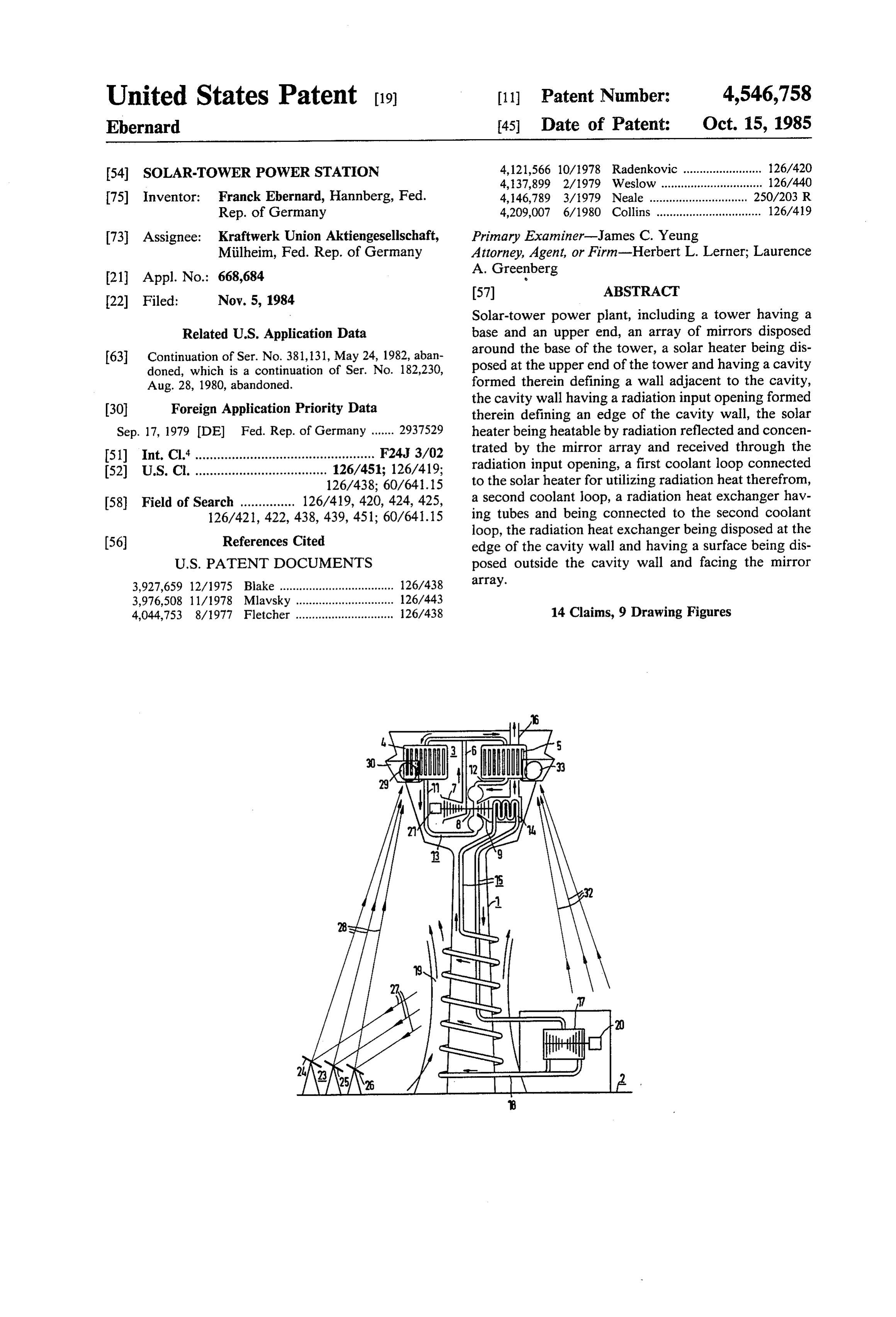
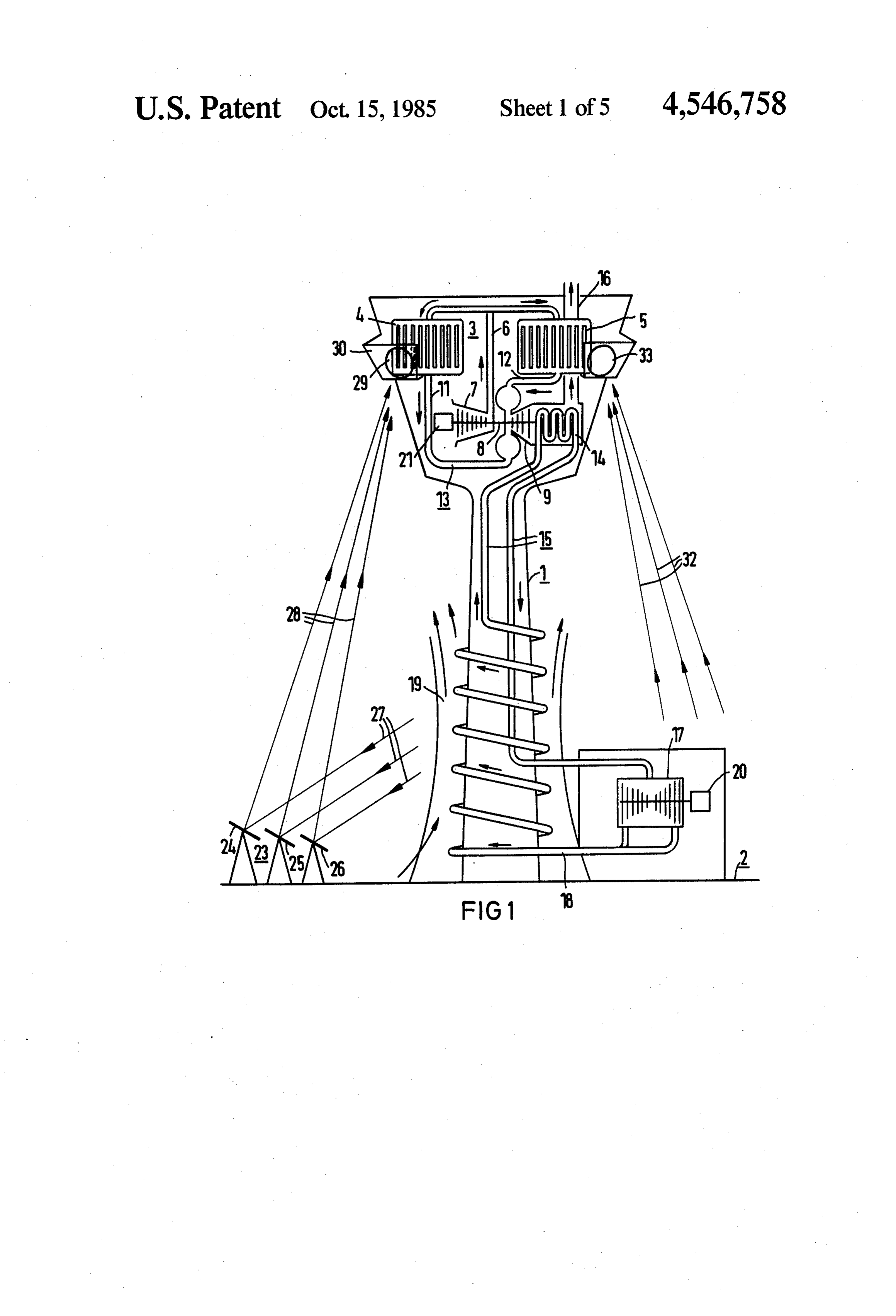
an evaporation section and a superheater section, de FIG. 1 is a diagrammatic side-elevational view of a pending on the temperature of coolant. solar-tower power station;
In accordance with yet another feature of the inven FIG. 2 is a fragmentary diagrammatic and graphical tion there are provided means for reversing the direc 20 view of the typical distribution of the reflected radiation tion of flow of coolant in the radiation heat exchanger in the vicinity of a radiation input opening; relative to the input opening. FIG. 3 is a diagrammatic cross-sectional view In accordance with yet a further feature of the inven through a cavity-type solar heater and the radiation tion, at least one of the tubes of the radiation heat ex input opening with the radiation heat exchanger ac changer is a measuring line, and there are provided 25 cording to the invention;
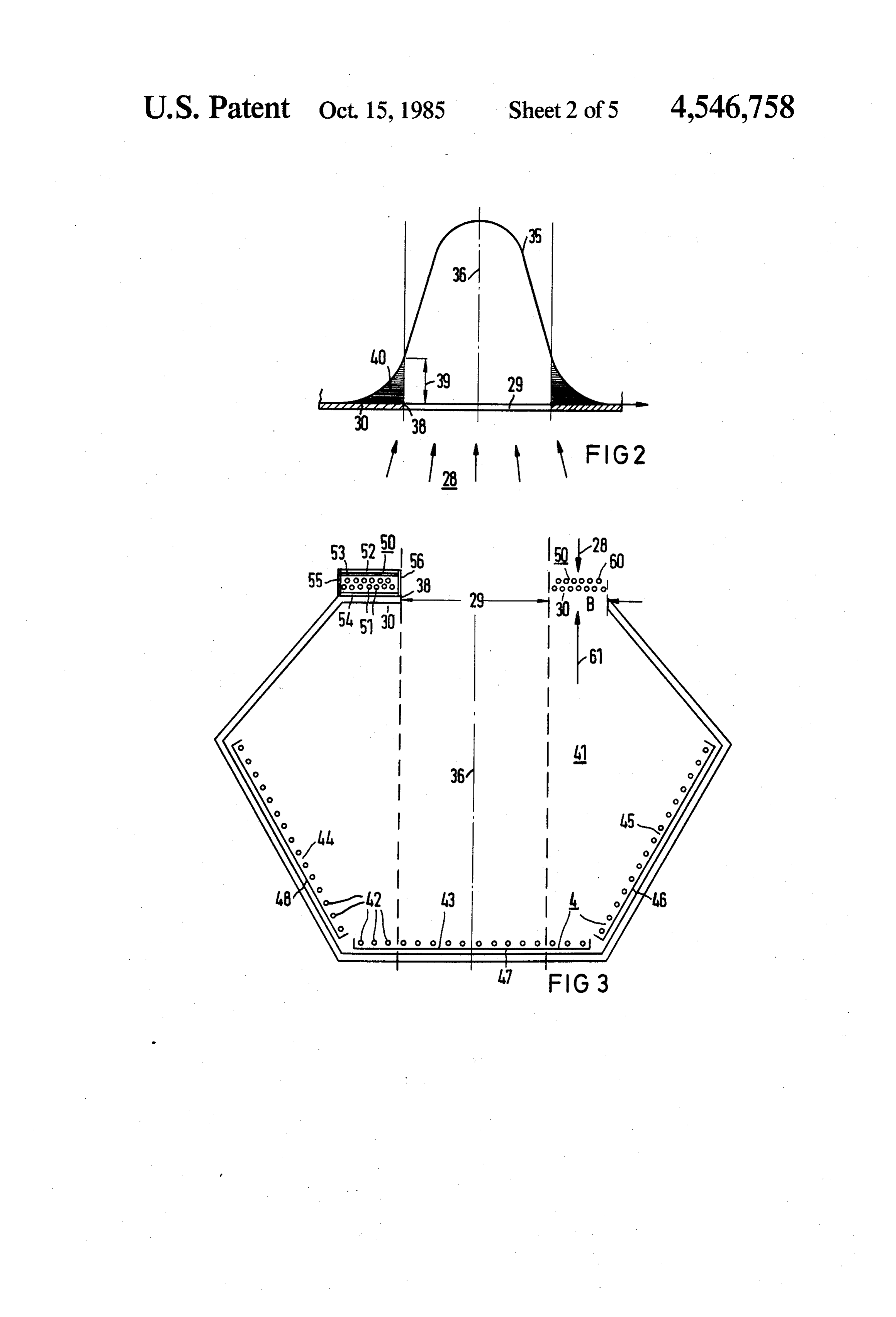
measuring sensors for temperature and mass flow con FIG. 4 is a cross-sectional view similar to FIG. 3 with nected to the at least one measuring line. a schematic circuit diagram for controlling the internal In accordance with yet an added feature of the inven radiation cavity by the external radiation heat ex tion, several distributed tubes of the radiation heat ex changer;
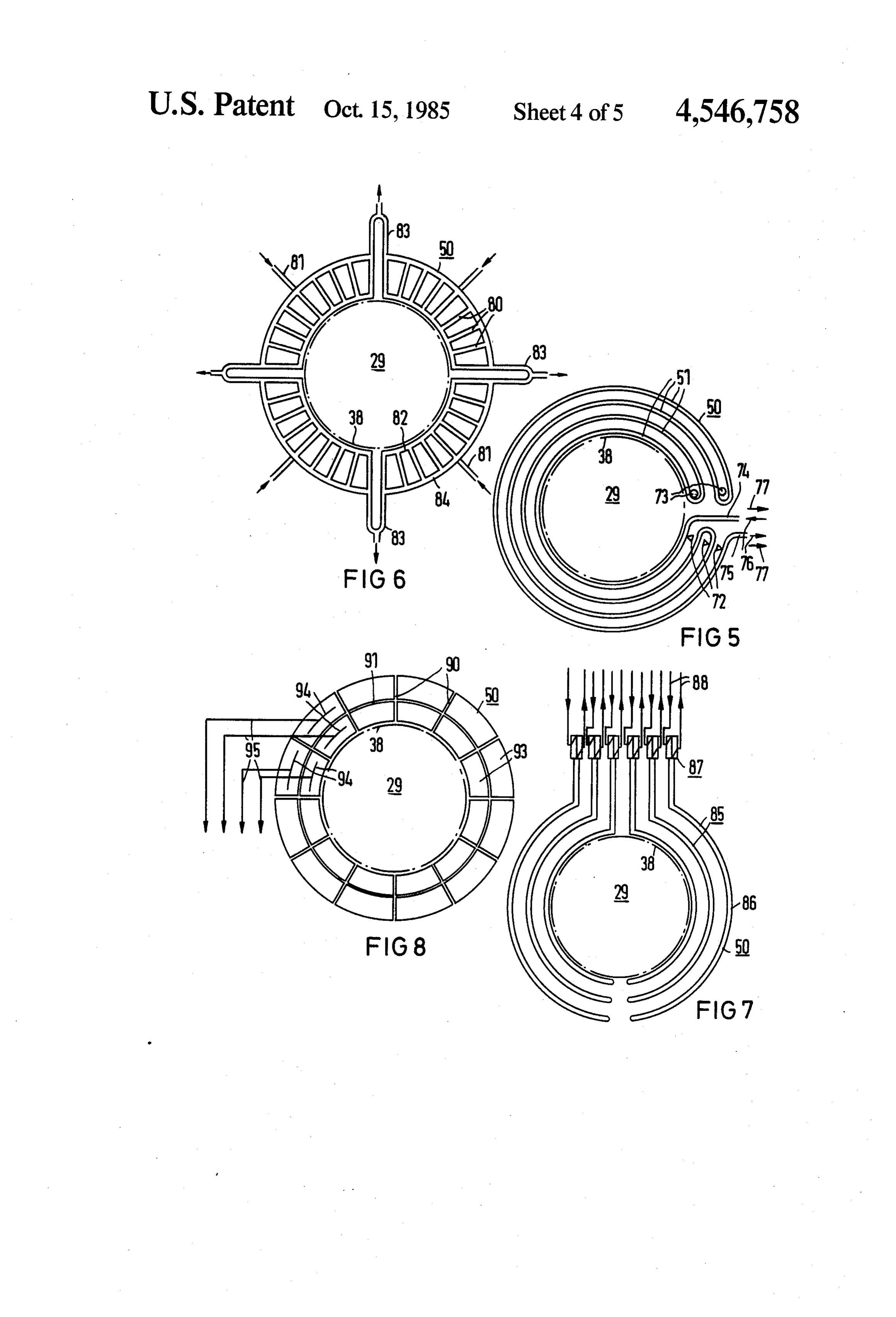
changer are in the form of a measuring line for deter 30 FIG. 5 is a diagrammatic elevational view of the tube mining the reflected radiation extending at a given dis bundle of a radiation heat exchanger with a flow direc tance beyond the edge of the cavity wall. tion parallel to the edge of the radiation input opening; In accordance with yet an additional feature of the FIG. 6 is a view similar to FIG. 5 of a tube bundle of invention, all of the tubes of the radiation heat ex a radiation heat exchanger with a flow direction sub changer are connected together in the form of a measur 35 stantially transverse to the edge of the radiation input ing line for calorimetric measurement of all of the re opening;
flected radiation. In this manner, even the intensity of FIG. 7 is a view similar to FIGS. 5 and 6 of an em the radiation which goes beyond the edge can be deter bodiment of the radiation heat exchanger with heat mined, which, without the invention, would have to be pipes;
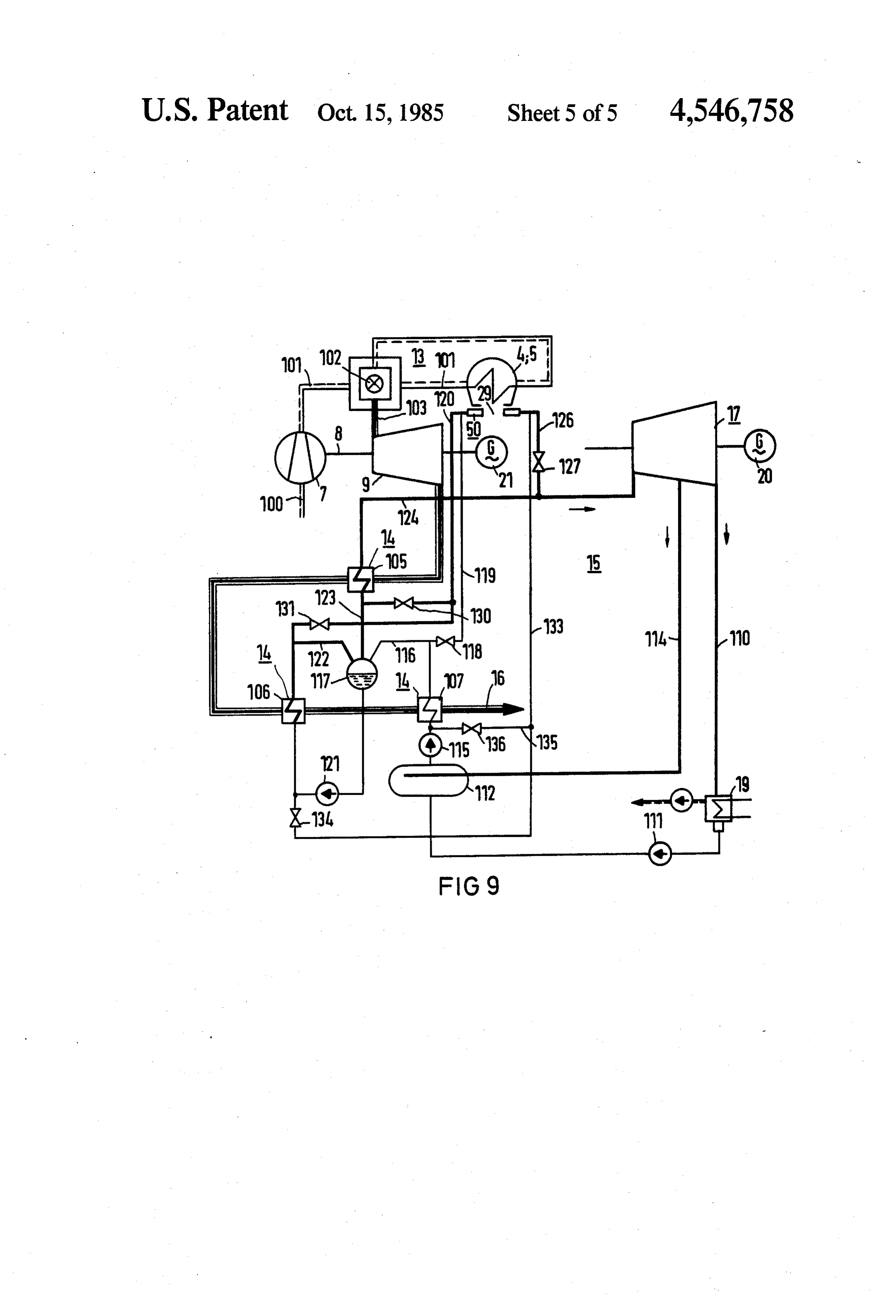
called a radiation loss, so that the full intensity of the 40 FIG. 8 is a view similar to FIGS. 5-7 of a possible total mirror array radiation becomes measurable. subdivision of a ring area associated with a radiation In accordance with again a further feature of the heat exchanger; and invention, there is provided a process computer con FIG. 9 is a diagrammatic and schematic circuit dia nected to the measuring line for controlling the mirror gram of an example of a circuit for possible coupling of array. 45 the useful heat obtained in a radiation heat exchanger In accordance with again another feature of the in into a gas or steam process.
vention, there is provided a control loop, preferably Referring now to the figures of the drawing and first equipped with a process computer, for optimising heat particularly to FIG. 1 thereof, it is seen that the solar utilization of the radiation heat exchanger, the measur tower power station includes a tower 1 which rises, for ing line being part of the control loop. With such a 50 instance, at least 40 m above ground level 2. At its upper process computer, provision can be made that the solar end 3, the tower supports one or more cavity-type solar heat which is obtained by the radiation heat exchanger heaters 4 and 5. The solar heaters are, in principle, bun and varies throughout the day, is optimally coupled into dles of tubes that are distributed in a large area, which a gas and/or steam process with constant or variable absorb solar heat and give it to a coolant which flows temperature level and correspondingly matched mass 55 through the tubes. To this end, the solar heaters are flow of the coolant. Thus, the daily cycle energy can be connected in parallel to the output line 6 of a compres maximized and the annual average efficiency improved. sor 7, which in the illustrated embodiment example The same process computer can also be used to perform circulates air as the coolant.
temperature-limit monitoring in cooperation with the The compressor 7 is connected by a shaft 8 to a gas radiation heat exchanger through the measuring lines of 60 turbine 9. Hot gas lines 11 and 12 of the two solar heat the latter and, in the event of distrubances, to cause fast ers 4 and 5 lead to the gas turbine 9. In the course of its defocusing of the mirror array, to assure the safety of loop or conduit 13, after the gas turbine 9, the hot gas the installation. (air) which leaves the lines 11, 12 and drives the gas Therefore, in accordance with a concomitant feature turbine 9 passes a heat exchanger 14 of a steam loop or of the invention, there are provided safty connection 65 conduit 15 before it leaves the chamber 3 or upper end means for increasing coolant flow in the tubes of the of the tower through an exhaust air stack 16. The gas radiation heat exchanger if operated above a given per loop 13 is then closed from the free atmosphere, from missible temperature limit. which the compressor 7 draws.
Page 10
From the steam loop 15 it can be seen that the live the infrared radiation range while the transmissivity steam line leading downward from the heat exchanger, should be as high as possible in the visible radiation which serves as a steam generator, ends at a steam tur range so that the energy of the reflected radiation 28 bine 17 mounted on the ground 2. Steam leaving the reaches the tubes 51. This may be done with selectively turbine 17 is conducted through a line 18 to a dry cool 5 absorbing and emitting coatings. ing tower 19, which is structurally combined with the The radiation heat exchanger 50 shown on the left tower 1, as shown. At the tower 19 the coolant is con side in the cross section according to FIG. 3, also has a densed and is transported as feedwater back to the heat large-area element 54 on the side thereof facing the exchanger 14. cavity wall 30 which is formed of ceramic material or of The steam turbine 17 drives an electric generator 20 O metal. The element 54 serves the purpose of letting the with an output rating of, say, 6 MWe. Besides the com radiation, as far as it misses the tubes 51 or emanates pressor 7, a generator 21 with a nominal power of, say therefrom, return to the tubes 51 by direct reflection or 14 MWe is connected to the shaft 8 of the gas turbine 9. by scattering. At the time, the large-area element 54, The solar heaters 4 and 5 are acted upon by the two especially if it is in the form of a ceramic plate, can form symmetrical mirror array segments which are disposed 15 heat insulation if this is desired. The side portions 55 and at the base of the tower 1. Of these, there is shown only 56 provide a lateral seal of the radiation heat exchanger the schematically illustrated individual mirrors 24, 25 50.
and 26 for one mirror array segment 23, which direct In the embodiment according to the right side of the incident parallel sun rays 27 toward the solar heater FIG. 3, a two-layer tube bundle 60 of the radiation heat 4 as focused reflected radiation 28 through a radiation 20 exchanger 50 is disposed in place of the cavity wall 30. input opening 29 in a wall 30 of the cavity. A similarly The tube bundle 60 is therefore, on the one hand, acted focused reflected beam 32 acts on the solar heater 5 upon directly by the reflected radiation 28 of the mirror through a second radiation input opening 33. array 23, as indicated by the arrow 28. In addition, FIG. 2 shows, in a simplified view, the cavity wall 30 however, it is also exposed to the back radiation, indi with the opening 29 formed therein and the reflected 25 cated by the arrow 61, from the cavity-type solar heater radiation 28 incident thereon. The local intensity of the 4.
radiation 28 is plotted in the form of a Gaussian curve In both embodiments according to FIG. 3, the radia 35, assuming rotation-symmetrical spatial distribution. tion heat exchanger 50 is a flat structure which is dis It is seen that the intensity is at a maximum in the vicin posed in ring-fashion in the plane of the radiation input ity of the axis 36 of the circular radiation input opening 30 opening 29. Its width is about one-third of the radiation 29 shown in dot-dash lines, but does not become zero in input opening, which in practice is about 6 m. step-fashion at the flanks; it rather still has an intensity In agreement with FIG. 3, the embodiment example value of, say, of the maximum intensity as designated according to FIG. 4 includes a cavity 41 with three tube with reference numeral 39, even at the edge 38 of the walls 43, 44, 45 which are disposed with a U-shaped radiation input opening 29. The radiation extending 35 cross section and are acted upon through the radiation beyond the edge 38, which is shown in FIG. 2 by the input opening 29 in the cavity wall 30. The radiation corner area 40 under the intensity curve 35, has as the heat exchanger 50 associated with the radiation input integral of the curve 35 in the embodiment example, opening 29 again includes a two-layer bundle 62 of about one-tenth the magnitude of the radiation passing tubes 51 which are disposed offset to each other. How through the radiation input opening 29. 40 ever, the layers are not disposed in the plane of the FIG. 3 shows, in a horizontal-sectional view, a cavi radiation input opening 29 but are formed at an angle ty-type solar heater 4 having a cavity 41 with a hexago thereto, as can be seen in FIG. 4, showing the horizon nal cross section, which is disposed at the top of the tal section through the center of the radiation input tower of the solar-tower power station according to opening 29. A three-dimensional, i.e., spatial arrange FIG. 1. The cavity 41 contains inner tubes 42 which, as 45 ment of the radiation heat exchanger 50 is therefore shown in FIG. 3, together have a U-shaped or approxi obtained.
mately semicircular cross section, because the vertical FIG. 4 further shows that a large-area element 63 is tubes 42 form a bridge or web-like region 43 and two associated with the two-layer tube bundle 62. The ele legs 44 and 45 with three tube walls that are disposed ment 63 acts as a reflection or, if applicable, as a scatter symmetrically to the axis 36. Reflection surfaces 46, 47 50 ing surface, and possibly also as a heat-conducting sur and 48 are associated with the web 43 and the legs 44 face for the radiation, which passes the tubes 51 or and 45. emanates therefrom. The large area element 63 is Located opposite the tube wall 43 of the solar heater formed of metal and has tubes 64 in heat-conducting 4 is the radiation input opening 29 in the cavity wall 30. contact on the side thereof facing away from the tube Two embodiments of the edge 38 of the opening 29 in 55 bundle 62, which may be connected to tubes 51 to form the wall 30 are shown to the right and the left of the a common cooling loop.
dot-dash center line, which coincides with the axis 36. It is further seen from FIG. 4 that the radiation heat A radiation heat exchanger 50 which surrounds the exchanger 50 can be coupled into the coolant loop of radiation input opening 29 in ring-fashion is associated the solar heater 4 in different ways. The radiation heat with the radiation input opening 29. 60 exchanger 50 can be connected in parallel or in series In the embodiment to the left in FIG. 3, the radiation with the tube walls 44 and 45 of the legs of the solar heat exchanger 50 includes a two-layer bundle of tubes heater 4 depending on which of the six valves 65 to 70 51 disposed in an offset manner; the layers being located are open or closed. In this way the asymmetrical expo on the outside of the cavity wall, parallel thereto. The sure of the solar heater 4 which varies during the day tubes 5i are provided with a one or more layer glass 65 can be compensated. A reduction of the thermal stresses cover 52. The glass cover 52 has a coating 53 which has and a more uniform output temperature for the coolant selective transmissivity on the side thereof facing the stream of the different tube walls 44, 45 are thereby tubes. It is desirous as little transmissivity as possible in achieved.
Page 11
FIG. 5 shows, in a simplified manner, that the radia the shadow zone of this zone, relative to the reflected tion heat exchanger 50 associated with the radiation radiation 28 incident perpendicularly to the plane of the input opening 29 includes a bundle of tubes 51 which drawing. The usable heat which can be taken out by the are connected in series to form a single coolant loop. secondary lines 88 of the heat exchangers 87 is again The tubes 51 are fitted to the edge 38 of the radiation 5 coupled into the cooling loop of the solar heaters 4, 5. input opening 29 shown in dot-dash lines, and are paral However, it could also be given off to the feed water lel thereto. The tubes 51 are rigidly secured at one end which flows through the steam generator 14 according thereof by means of fixation points 72. At the other to FIG. 1. Various possibilities for decoupling into the ends, sliding points 73 are provided for fastening, so that steam process of the solar-tower power station for this the tubes 51 can expand without impediment in their 10 purpose will be described hereinbelow, referring to lengthwise direction when heated up. FIG. 9.
FIG. 5 also diagrammatically shows that the coolant FIG. 8 shows that the ring area of the heat exchanger can be admitted to the connecting lines 74 and 75 of the 50 surrounding the radiation input opening 29 can be radiation heat exchanger 50 with reversible direction of subdivided along parting lines 90 which are radially flow. Therefore air, for instance, can be made to flow as 15 directed in the embodiment example, and more gener a gaseous coolant through the radiation heat exchanger ally are transverse to the edge 38. Another possibility 50 in such a way that it is transported from the region for a subdivision is indicated by a parting line 91 which near the edge to the region further removed from the extends parallel to the edge 38, or more generally along edge, before it leaves the radiation heat exchanger 50. the edge, so that segments are produced. Maximum cooling is achieved in this way; i.e. the heat 20 The parting lines 90 and 91 may, for instance be ex absorption in the region near the edge is maximized. pansion gaps in metallic or ceramic surfaces, which are After switching over, however, the coolant can also associated with the tubes of the heat exchanger 50. first flow in the tubes 51 that are removed from the edge Selectively absorbing and emitting coatings may be and then through these toward the region near the edge, added to the surfaces of the tubes. This can likewise be before it leaves the region near the edge with the high 25 in the form of a subdivision of a glass cover of the radia est possible temperature. The average direction of the tion heat exchanger described in connection with FIG. tubes 51 is parallel to the edge 38 in both cases, as al 3. Finally, the subdivision, provided by the individual ready mentioned. sectors and segments of the ring area of the radiation In the embodiment example according to FIG. 6, on heat exchanger 50 forming sections 93 can also be un the other hand, the radiation heat exchanger 50 is con 30 derstood structed in such a way that the tubes 80 extend trans which aretoconnected be in the form of individual tube bundles, versely to the edge 38, which is indicated in dot-dash by suitable connecteddifferently in series or in parallel lines with a length corresponding to the width of the optimum utilization of the differentcontrolled lines with radiation valves for intensities, ring area. With the circular shape of the opening 29 as indicated, the tubes 80 are radial. According to the 35 forItoptimizing the efficiency of the heat absorption. is further indicated in FIG. 8 that a tube 94 in the arrows in FIG. 6, there are provided inlet lines 81 that form of a measuring line is associated with each section lead to the part near the edge of the radiation heat ex 93 of the radiation heat exchanger 50. In the embodi changer 50, which is represented by the manifold 82. ment example the tube 94 is situated in the central por The discharge lines 83 are associated with a manifold 84 tion of each section 93. The tube 34 is provided with spaced away from the edge. The manifold 84 confines 40 suitable sensors for temperature and mass flow rate, so the ring area toward the outside, which is covered by that the heat the radiation heat exchanger 50 that surrounds the edge measurementabsorption can be determined to allow the of the local radiation intensity. These may 38 of the radiation input opening 29. This further shows be in the form of photo-elective semiconductor ele that in this embodiment as well the width of the radia tion heat exchanger is far more than one-tenth of the 45 ments or solar cells which can be force-cooled by the tubes 51. The electrical measurement value(s) of the inside width of the radiation input opening 29, as given sensors by the diameter. In the embodiment according to FIG. process computer,is(are) then transmitted through lines 95 to a 6, the width of the ring area is again about one-third of process computer can which is not specifically shown. The the diameter. optimize the coupling of the solar Through the feed and discharge lines 81, 83, which 50 heat striking the edge area and can thereby optimize the incidentally can also be used for the reverse flow direc the efficiency of the sun-tower power station by controlling tion, a quadrant-wise sub-division of the ring area of the changerindividual sections 93 of the radiation heat ex radiation heat exchanger 50 is obtained in the embodi 50.
ment example according to FIG. 6, which is advanta In addition, the same process computer can influence geous for compensating thermal expansion. Instead, or 55 the control of the individual mirrors 24, 25, 26, so that in addition thereto, compensators in the form of metal the radiation striking the edge area does not exceed the bellows can also be used for compensating thermal desired value and/or optionally a permissible limit. In expansion. the event of an accident, for instance, or of a failure of FIG. 7 diagrammatically indicates the use of heat the coolant supply or the positioning devices of the pipes 85 as elements of a radiation heat exchanger 50. 60 mirrors 24 to 26, the process computer can also initiate The heat pipes 85 with their evaporator zone 86 are auxiliary measures. For this purpose, the radiation heat parallel to the edge 38 of the radiation input opening 29 exchanger can be operated with increased coolant flow, that is again indicated by dot-dash lines. The condensa for instance, in case of overheating. tion zone associated with a heat exchanger 87 is dis In the case of a coolant failure, the auxiliary measures posed above the evaporator zone 86. Contrary to the 65 triggered through measuring lines or tubes 94 or initi appearance of the view in FIG. 7, it is angled off from ated directly in the event of accidents may further in the plane of the evaporator zone, so that the heat ex clude directing the reflected radiation 28 away from the changers 87 lie "behind' the evaporator zone 86, i.e., in area of the tower 1 by moving the mirrors 24, 25, 26. In
Page 12
some circumstances, another coolant source can also be by the feedwater pump 115 through the line branch 133 taken into operation. into the radiation heat exchanger and flows through The measuring lines 94 can be used for determining lines 119 and 116 into the drum 117. The input tempera the total radiation power of the mirror array if the rela ture of the feedwater flowing into the radiation heat tionship of the radiation entering the cavity 41 through exchanger 50 is then, for instance, only 50° C. the radiation input opening is known in relation to the If the valve 134 is opened simultaneously with the radiation 40 which acts on the radiation heat exchanger valve 131, the radiation heat exchanger 50 can operate 50. For this purpose, the entire radiation heat exchanger in parallel with the evaporator 106, because it is acted can also be used. upon by the pump 121 and supplies steam through the FIG. 9 shows a piping diagram of the solar-tower O valve 131 into the line 122. The steam temperature after power plant of FIG. 1, from which the different cou the radiation heat exchanger 50 can then be about 150 pling possibilities for the radiation heat exchanger 50 for to 200 C.
utilizing its usable heat in the existing gas and steam Finally, the radiation heat exchanger 50 can also be circuits 13, 15 can be seen. operated as a superheater by opening the valves 130 and The shaft 8 of the gas turbine 9 drives the compressor 15 127. Then it is supplied with steam from the drum 117, 7, which draws atmospheric air with a suction line 100 which is then given off directly into the hot-steam line and pushes it from its outlet side through a line 101 into 124. In this operation the end temperature after the a combustion chamber for supplemental fossile firing. radiation heat exchanger 50 is, for instance, 350° C. Behind or downstream of the combustion chamber 102, As shown in FIG. 4, it is also possible to couple the the pressure line 101 leads to the cavity-type solar 20 radiation heat exchanger 50 at the radiation input open heater 4, 5 and from there with the line branch 103 to ing 29 into the gas loop 13 if sufficiently high tempera the gas turbine 9 which is operated at 8 bar and 800° C. ture between, for instance, 500 and 800 C. can be The expanded hot gas leaving the gas turbine 9 at 380 reached thereby. In view of the shielding effect which C. then passes through the heat exchanger 14 which, may be intended by the radiation heat exchanger 50 for according to FIG. 9, is constructed with three parts. 25 the structure of the sun-tower power station, the low The first part 105 of the heat exchanger 14 acts as a temperatures of the steam loop 15 may, however, be superheater. The second part 106 of the heat exchanger better suited for heat removal, i.e., the utilization of the 14 serves as the evaporator. After a third part 107 of the solar heat by the radiation heat exchanger 50. heat exchanger 14, which acts as a preheater, the air, What is claimed is:
that is cooled down to 105 C., leaves the solar-tower 1. Solar-tower power plant comprising a tower hav power plant through the discharge line 16 into the at ing a base and an upper end, an array of mirrors dis mosphere. posed around said base of said tower, a non-reflective The steam turbine 17 with the generator 20 has two cavity-type solar heater being disposed at said upper stages. An outlet line 110 leads from the low-pressure end of said tower and having a cavity formed therein part to the condenser formed by the dry cooling tower 35 defining a wall adjacent to said cavity, said cavity wall 19. From the tower 19, the feedwater is conducted by a having a radiation input opening formed therein defin pump 111 to a feedwater tank 112. A discharge line 114 ing a non-reflective edge of said cavity wall, said solar of the high-pressure part is also conducted into the heater being heatable by radiation reflected and concen feedwater tank 112. The line 114 can serve as the tap trated by said mirror array and received through said line for pre-heating the feedwater. 40 radiation input opening, a coolant conduit connected to From the feedwater tank 112, the feedwater can be said solar heater for utilizing radiation heat therefrom, a pumped by a pump 115 into the preheater 107. The radiation heat exchanger having tubes and being con preheater, in turn, is connected by a line 116 to a steam nected to said coolant conduit, the tubes of said radia drum 117. It is further connected by way of a valve 118 tion heat exchanger being disposed in a ring around said and a line branch 119 to the connecting line 120 of the 45 non-reflective edge of said cavity wall outside said cav radiation heat exchanger 50. ity wall facing said mirror array means having a surface From the drum 117, a pump 121 can pump feedwater area disposed in vicinity of said tubes and facing said at saturation temperature into the evaporator 106. The cavity wall for influencing heat transfer to said tubes at evaporator 106 is in turn connected by a line 122 to the least by at least one of heat conduction and back radia steam space of the drum 117, to which the superheater 50 tion, said radiation heat exchanger having a highly tem 105 is connected through a line 123. From the super perature resistant glass cover being disposed on the heater 105, the hot-steam line 124 leads to the steam tubes of said radiation exchanger for reducing convec turbine 17. tion losses, said glass cover having expansion gaps The radiation heat exchanger 50 is connected, on the formed therein forming segments, and a lateral seal one hand, to a line branch 126, having a valve 127, 55 disposed on said glass cover, wherein said glass cover is which leads to the hot-steam line 124. The line 120 is highly permeable ins the visible radiation range, and connected through a valve 130 to the line 123. A further including a selective coating disposed on at least part of valve 131 closes off the connection to the line 122. The said glass cover for reducing heat radiation and making line 126 is connected by a line 133 with a valve 134 to said glass cover less permeable in the infra-red heat the output side of the pump 121, and by a line branch 60 radiation range.
135 with a valve 136 to the outlet side of the pump 115. 2. Solar-tower power plant accordance to claim 1, With the depicted construction of the connecting wherein the tubes of said radiation heat exchanger are lines, the radiation heat exchanger 50 can be switched adapted to the cross section of said radiation input open into the steam loop 15 of the steam turbine 17 in differ ing and cover said edge of said cavity wall over a width ent ways, depending on its temperature. If, for instance, 65 of at least one-tenth of the diameter thereof. the valves 136 and 118 are opened, the radiation heat 3. Solar-tower power plant according to claim 1, exchanger 50 is acted upon by feedwater in operation wherein said tubes of said radiation heat exchanger are parallel to the preheater 107; the feedwater is conducted heat pipes.
Page 13
4. Solar-tower power plant according to claim 3 disposed around said input opening in the form of a wherein said heat pipes include a condensation and an three-dimensional spatially-curved ring surface. evaporation zone, said condensation zone being dis 10. Solar-tower power plant according to claim 1, wherein said tubes of said radiation heat exchanger are posed above said evaporation zone and out of the re disposed in a plurality of layers offset relative to each flected radiation. other.
5. Solar-tower power plant according to claim 1, 11. Solar-tower power plant according to claim 1, including photo-electric semiconductor elements dis wherein said tubes of said radiation heat exchanger are posed in vicinity of the tubes of said radiation heat 10 combined in a tube bundle extended parallel to said exchanger. edge of said cavity wall.
6. Solar-tower power plant according to claim 5, wherein 12. Solar-tower power plant according to claim 1, wherein said semiconductor elements are forced-cooled said tubes of said radiation heat exchanger are combined in a tube bundle extended transverse to said by said tubes of said radiation heat exchanger. edge of said cavity wall.
7. Solar-tower power plant according to claim 1, 15 13. Solar-tower power plant according to claim 1, including means for compensating expansion of said including a ring area of said cavity wall adjacent to said tubes of said radiation heat exchanger and means for edge thereof, said tubes of said radiation heat exchanger securing said tubes. being combined into a plurality of tube bundles, each of 8. Solar-tower power plant according to claim 7, 20 said14.tube bundles covering a part of said ring area. Solar-tower power plant according to claim 13, including ring elements surrounding said edge of said including means for selectively connecting said tube cavity walls, said large-area elements being subdivided bundles for use as a preheater section and an evaporator by expansion gaps formed therein. section and a superheater section, depending on the 9. Solar tower power plant according to claim 1, temperature of coolant. ak sk 2k k k wherein said tubes of said radiation heat exchanger are 25
Page 14
UNITED STATES PATENT AND TRADEMARK OFFICE
CERTIFICATE OF CORRECTION
INVENTOR(S) : . FRANCK EBERHARD
it is Certified that error appears in the above-identified patent and that said Letters Patent are hereby Corrected as shown below: On the Title Page:
In the heading, item (75), line li, "Franck Ebernard" should read
Signed and Sealed this
Seventh Day of April, 1987
Attest:
DONALD J. QUIGG
Attesting Officer Commissioner of Patents and Trademarks

Provenance
- Collection
- Cited prior art
- Original PDF
- patentimages.storage.googleapis.com →
- Filed
- 1984-11-05
- Pages
- 14
- Method
- pdftotext (the PDF's own text layer) + pdftoppm 300dpi page scans
- Source
- Google Patents bibliographic record
- Granted
- 1985-10-15
- Inventors
- Franck Ebernard; Kraftwerk Union AG
- Transcribed from
- patentimages.storage.googleapis.com →