patent · US4619244
Solar heater with cavity and phase-change material
28 October 1986
Page 1 — bibliographic record
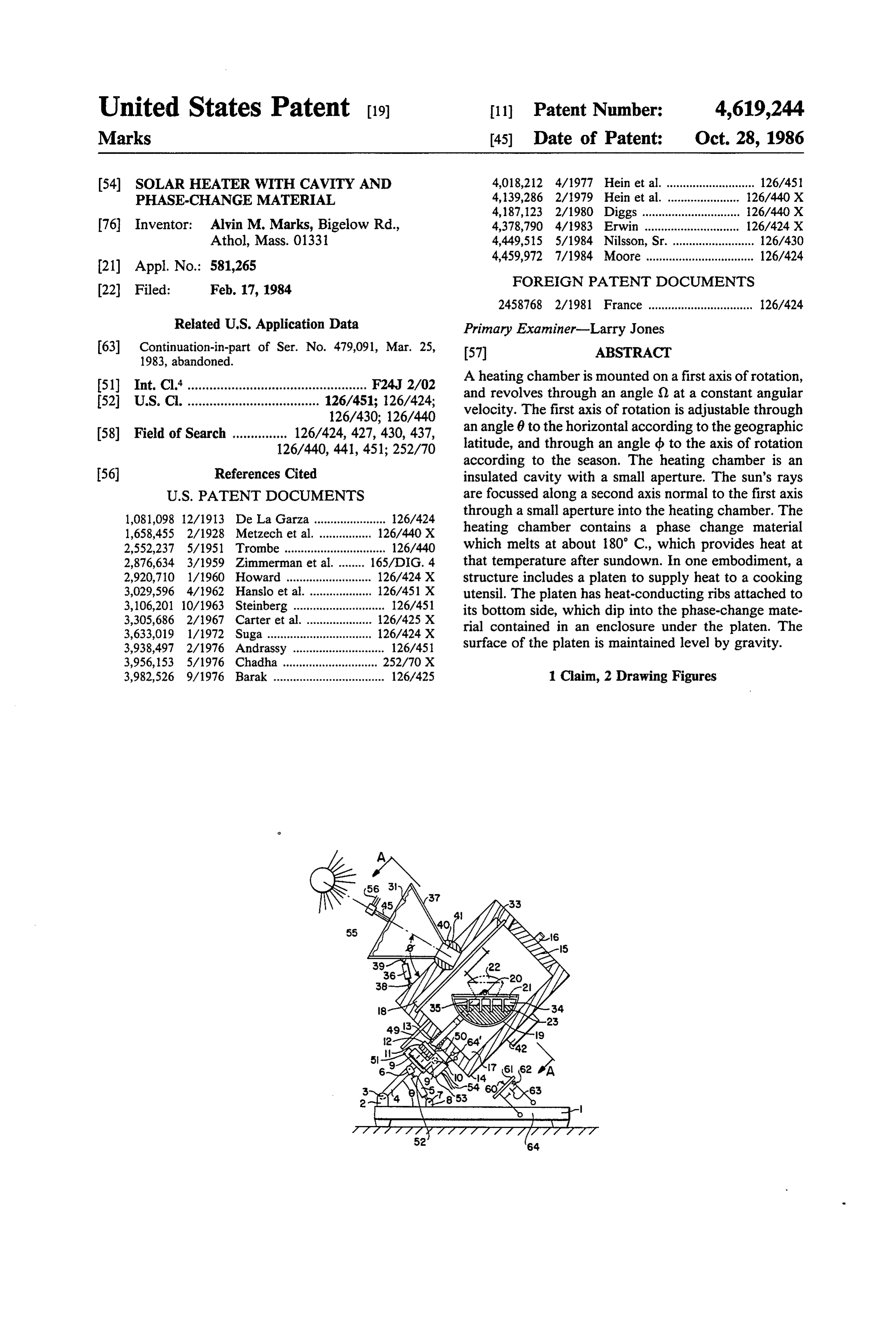
United States Patent (19) 11 Patent Number: 4,619,244 Marks (45) Date of Patent: Oct. 28, 1986 (54) SOLAR HEATER WITH CAVITY AND 4,018,212 4/1977 Hein et al. ........................... 126/451 PHASE-CHANGE MATERIAL 4,139,286 2/1979 Hein et al. .. ... 126/440 X 4,187,123 2/1980 Diggs ...... ... 26/440 X 76 Inventor: Alvin M. Marks, Bigelow Rd., 4,378,790 4/1983 Erwin ......... ... i26/424 x Athol, Mass. 01331 4,449,515 5/1984 Nilsson, Sr.. ...126/430 4,459,972 7/1984 Moore ................................. 126/424
FOREIGN PATENT DOCUMENTS
2458768 2/1981 France ................................ 126/424
Related U.S. Application Data Primary Examiner-Larry Jones 63) Continuation-in-part of Ser. No. 479,091, Mar. 25, 57 ABSTRACT 1983, abandoned.
(51) Int. Cl."................................................. F24J 2/O2 A heating chamber is mounted on a first axis of rotation, 52 U.S. C. .................................... 126/451; 126/424; and revolves through an angle () at a constant angular 126/430; 126/440 velocity. The first axis of rotation is adjustable through (58) Field of Search ............... 126/424, 427, 430, 437, an angle 6 to the horizontal according to the geographic 126/440, 441, 451; 252/70 latitude, and through an angle d to the axis of rotation according to the season. The heating chamber is an 56 References Cited insulated cavity with a small aperture. The sun's rays
1,081,098 12/1913 De La Garza ...................... 126/424 through a small aperture into the heating chamber. The 1,658,455 2/1928 Metzech et al. 126/440 X heating chamber contains a phase change material 2,552,237 5/1951 Trombe ............................... 126/440 which melts at about 180° C., which provides heat at 2,876,634 3/1959 Zimmerman et al ... 165/DIG. 4 that temperature after sundown. In one embodiment, a 2,920,710 1/1960. Howard .............. ... 126/424 X structure includes a platen to supply heat to a cooking 3,029,596 4/1962 Hanslo et al. ... 126/451 X utensil. The platen has heat-conducting ribs attached to 3,106,201 10/1963 Steinberg ............................ 126/451 its bottom side, which dip into the phase-change mate 3,305,686 2/1967 Carter et al. 126/425 X rial contained in an enclosure under the platen. The 3,633,019 1/1972 Suga............ 126/424 X 3,938,497 2/1976 Andrassy .... ... 126/451 surface of the platen is maintained level by gravity. 3,956,153 5/1976 Chadha ....... ... 252/70 X 3,982,526 9/1976 Barak .................................. 126/425 1 Claim, 2 Drawing Figures
Page 2
Drawing sheet — no readable text.
Page 3
The first cavity 18 is sealed from the second cavity 17
SOLAR HEATER WITH CAVITY AND by a separator plate 33. Sun energy heats the walls of PHASE-CHANGE MATERIAL the cavity 18 and a separator plate 33, which reradiates the sun energy into the chamber 17. The heat energy
This invention is a continuation in part of the patent heats the chamber 17 to the melting point of the phase application entitled Solar Cavity Cooker, Ser. No. change material 23 which absorbs heat energy as a 479,091 filed on Mar. 25, 1983, now abandoned. latent heat required to melt the phase change material.
BACKGROUND OF THE INVENTION
The molten material 23 may tend to expand as it changes phase. To accommodate this expansion, an air
Reference is made to the parent patent application in 10 chamber 34 is provided above the phase change mate which the prior art relating to solar cookers was sum rial 23. The platen 21 is cast with the ribs 35, which dip marized and illustrated. The present device is a further into the phase change material 23, and provide a con development of the solar cavity cooker disclosed in said duction path for the heat to pass from the phase change prior patent application characterized by a sun-follow material 23 to the platen 21 on which for example, a ing solar cavity, which enables the light power of the 15 cooking vessel 22 is placed. In this manner a good heat sun to be efficiently utilized. conduction path is provided between the phase change
IN THE FIGURES
material 23 and the platen 21. An air space 34 is located above the phase change material 23 to accommodate its
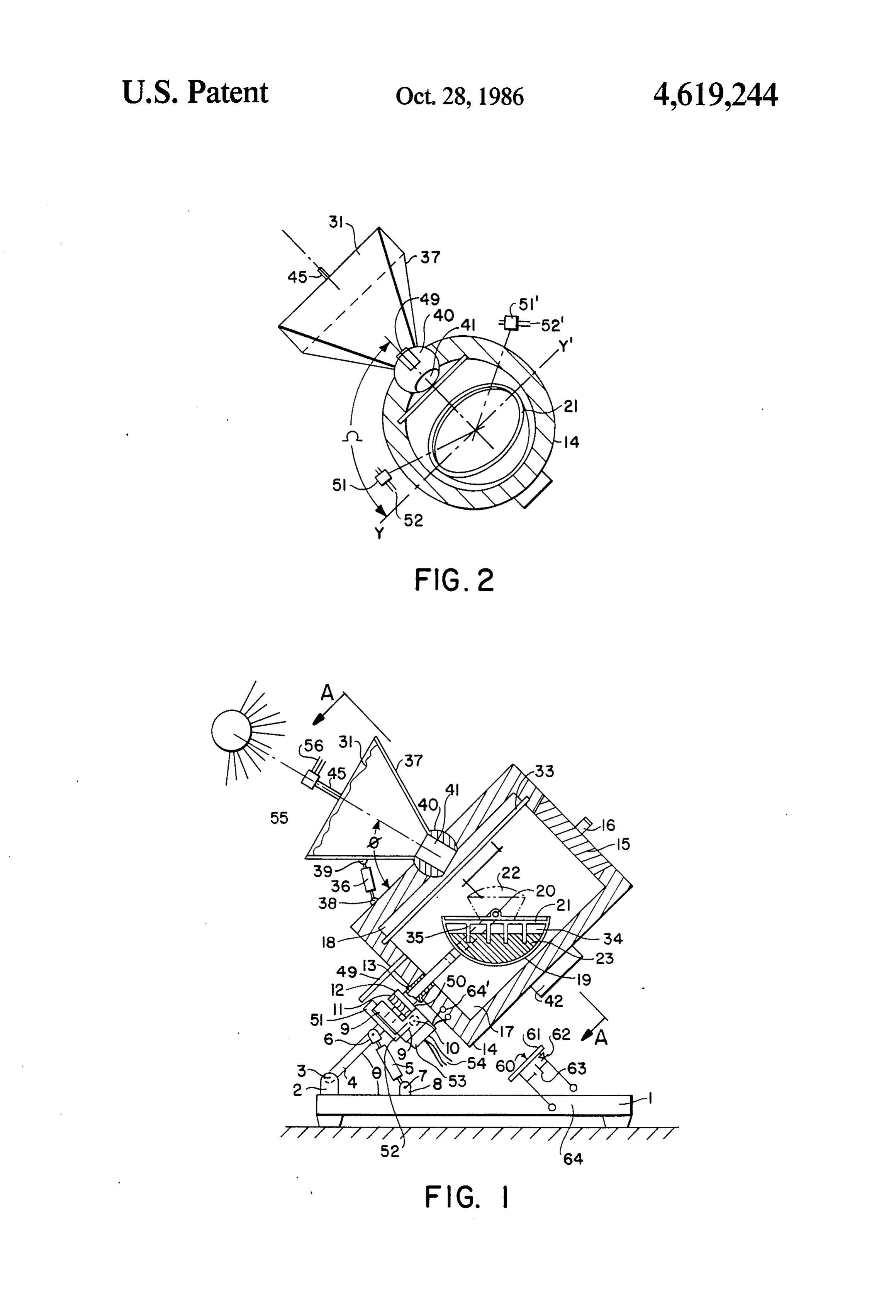
FIG. 1 shows a cross section of a rotatable heating expansion or contraction as it changes state. The Fres chamber of this invention. 20 nel surface 31 is maintained normal to the sun at all FIG. 2 is a view normal to the axis of the rotatable times by a small clock motor 9. The clock motor 9' may heating chamber. be electrically, spring or gravity-weight driven. It is mounted on the bracket 8 attached to the member 4.
DESCRIPTION OF THE INVENTION The member 4 is adjusted for the latitude angle 0; for In the parent patent application FIG. 6 shows a Fres 25 example, by the turn buckle 5; an adjustment being nel lens which is angularly adjustable to concentrate made once for each geographic location. A further sun's energy into a stationary cavity as a heated enclo adjustment through the angle d is made for the seasonal sure; and FIG. 7 shows a similar device in which a variation of the sun's position. The angle d is adjusted Dewar flask cavity is tilted to focus the sun's rays into by turn buckle 36 connected between the support frame the aperture of the cavity. 30 37 on the Fresnel lens 31, and the chamber surface 34 by In this invention an improved sun-following structure brackets 38 and 39 respectively. The frame support for is employed, which solved a number of the outstanding Fresnel lens 31 has a shape of a truncated pyramid in problems with the earlier invention. There was the verted with its base up and its apex near the focal point problem of isolating the cavity from the cooker cham of the Fresnel lens. The Fresnel lens support structure is ber so the vapors from the heated food cannot deposit 35 attached to a spherical member 40, which may be a on to the lens surfaces, which would damage the lens portion of a sphere having an internal aperture 41 to surface and obscure the light focussed into the cavity. provide a passage for the sun's rays. The rotatable mem The present device also includes an efficient heat trans ber 40 is mounted in an aperture on the side of the cylin fer means for transmitting the heat energy from the drical chamber 14. The Fresnel lens and the chamber is phase change material to the cooking platen on which 40 counter weighted by a counter weight 42 to balance the the food is cooked. assembly. The chamber and the lens structure may then Referring to FIG. 1, a base 1 has a bracket 2 support be rotated through the angle (), measured from the YY' ing a pivot pin 3 to which the tiltable axial member 4 is horizontal axis shown in FIG. 2, proportional to the attached. The axial member 4 is adjustable at an angle 6 time of the day with relatively little power by the clock to the horizontal, for example, by a turnbuckle 5, which 45 motor 9"; for example, about 5 watts. is secured to the base by the bracket 8, and to the axial The FIG. 2 shows a view normal to the axial member member 4 by pins at 6 and 7 respectively. A plate is 4. The Fresnel lens 31 is supported on the mounting mounted on axial member 4, and a clock motor 9" is frame 37 which is attached to a spherical member 40 mounted on the plate 9. The clock motor operates a which has an internal aperture 41. The top of the platen worm 10, which meshes with worm gear 11. The worm 50 21 is also shown in this view.
gear 11 is secured to a sleeve 12, which rotates on the Phase change materials may be selected from certain axial member 4, and which is also secured at 13 to the solids which melt in the range of 150° C. to 250' C. insulated chamber 14, which may be cylindrical. The Certain organic substances may be employed; for exam chamber 14 has a insulated door 15, which may be ple, Hydroquinone (also known as Quinol) a melting opened with the handle 16. The door may be removable 55 point of 172 C. and latent heat of 2.46X 10 joules/Kg; or on a hinge. Within the chamber 14 are two cavities 17 or, ortho-phthalic acid which has a melting point of and 18. Cavity 17 contains the heating element 19 which 194° C. and latent heat 3.16X 10⁵ joules/Kg. Other is suspended from a pivot point 20, mounted on the phase change materials may be used; for example, a member 4. The heating element 19 and the platen sur metal such as tin which melts at 232 C., and has a latent face 21 rests in a horizontal position with its center of 60 heat 0.59x 10⁵ joules/Kg. In a chamber 50 centimeters cavity below the pivot point 20. The heating element 19 in diameter, with a wall insulation thickness of 10 centi is a flat surface platen 21, on which a pot or other utensil meters, a 8 Kg of a phase change material such as Qui 22 is located to receive the heat generated in the cham nol may be employed to maintain a temperature of ber. Heat is stored in phase change material 23 which about 180° C. for about four hours after sundown in the melts at about 180 C. to 200 C. and provides heat to 65 chamber 17 and the plante 21. If necessary an additional the chamber after sundown to maintain its temperature quantity of phase change material may be employed and for many hours. Sun energy is focused through an ori distributed around the walls of the chamber. To in fice 41 to a sealed first cavity 18 within the chamber 14. crease the heat retention time so as to maintain the
Page 4
temperature until sunup, about 20 Kg of phase change A photosensor 55 may be employed to keep the axis material may be required, the amount required being of the Fresnel lens parallel to the suns rays. Signals are dependent on the insulation effectiveness. sent via 3 wire leads 56 to the servomotor 53 via leads The mechanism for rotating the chamber to the start 54 to position the Fresnel lens so that it focuses the suns ing position at sunrise: For example, there may be a 5 energy through the cavity aperture 41 at all times. A photocell 61 of about 20 cm X20 cm area provides manual ratchet override to suitably position the Fresnel sufficient lens. A rod similar to a sun dial may be mounted to the the motorpower from the sun 60 (a few watts) to drive surface of the Fresnel lens to enable the adjustment of noted. The photocellposition
61 diode 62 and storage battery 63 the angular position of the Fresnel lens surface normal 10 stores energy when the motor is drawing little or no to the sun's rays. The latitude angle 6, seasonal angle db, power to turn the chambers 14. and rotation angle () may be adjusted independently to This invention utilizes an efficient new concentrator adjust the Fresnel lens surface. The rod 45 attached to and a cavity. While a Fresnel lens is employed in a the Fresnel lens indicates that the surface of the Fresnel preferred embodiment of this invention, it will be un lens is normal to the sun's rays by projecting no shadow. 15 derstood that other sun concentrating means such as a It will be understood that the solar cavity device parabolic reflector may be employed instead. Various herein disclosed has many uses other than as a cooking modifications of this invention may be made without stove; for example, it may be used as an efficient heat departing from the scope of this invention. source to provide steam for conversion to electric What I wish to claim is:
power, for heat transmission via heat pipes or for other 20 1. A solar heating device comprising an insulating heating purposes well known to the art. chamber, an aperture on said chamber, sunfollowing Various means may be employed to accurately posi means for poncentrating and focussing sunlight through tion the focus spot of the sun's rays, so that the spot is said aperture into said chamber, a platen in said cham located within the aperture at all times. Bimetallic ber, a heat-conductive ribbed element attached to a strips; or photo or thermo sensors, and electronic servo 25 surface on said platen, a phase-change material, a con circuits well known in the art may also be employed for tainer for said phase-change material, said platen being this purpose. sealed to said container, said ribbed element dipping FIGS. 1 and 2 show a clutch 49 between the motor into said phase-change material, an air space above said drive 9' and the rotatable chamber 14 which may be phase-change material, said phase-change material melt used to override the and manually position the axis of 30 ing at a temperature suitable for cooking food, whereby the Fresnel lens parallel to the sun. heat is provided to said platen to increase and maintain Limit switches 51 and 51' disconnect, or reverse the the said temperature of the said platen within the said motor to keep the angle 52 between limits. For example chamber. 2 : : - ak
Provenance
- Collection
- Cited prior art
- Original PDF
- patentimages.storage.googleapis.com →
- Filed
- 1984-02-17
- Pages
- 4
- Method
- pdftotext (the PDF's own text layer) + pdftoppm 300dpi page scans
- Source
- Google Patents bibliographic record
- Granted
- 1986-10-28
- Inventors
- Alvin M. Marks
- Transcribed from
- patentimages.storage.googleapis.com →