patent · US4402306
Thermal energy storage methods and processes
6 September 1983
Page 1 — bibliographic record
126 - 43. A 3, 4 ty
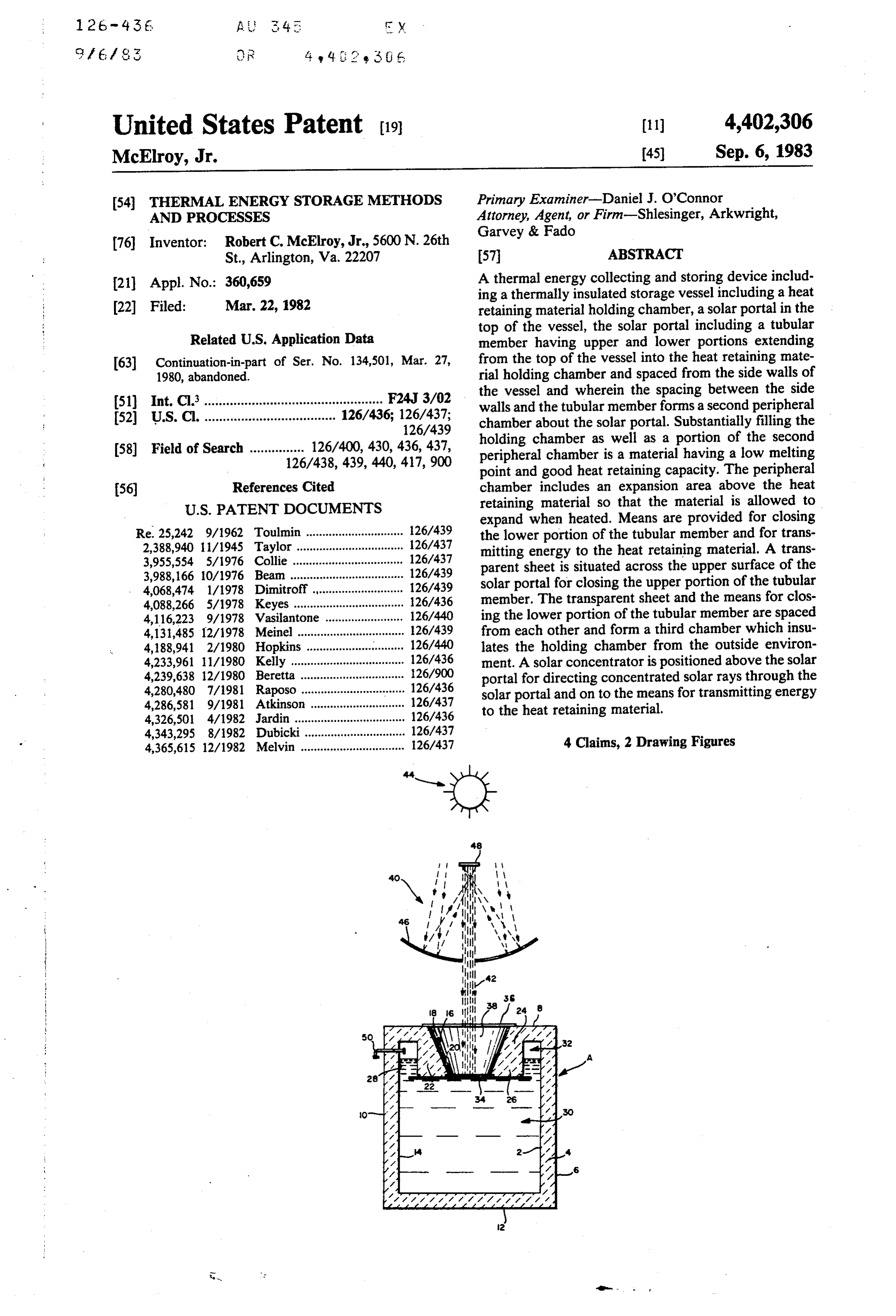
United States Patent (19) 11 4,402,306 McElroy, Jr. 45) Sep. 6, 1983
(54) THERMAL ENERGY STORAGE METHODS Primary Examiner-Daniel J. O'Connor AND PROCESSES Attorney, Agent, or Firm-Shlesinger, Arkwright, Garvey & Fado 76 Inventor: Robert C. McElroy, Jr., 5600 N. 26th
St., Arlington, Va. 22207 57 ABSTRACT (21) Appl. No.: 360,659 A thermal energy collecting and storing device includ ing a thermally insulated storage vessel including a heat (22 Filed: Mar. 22, 1982 retaining material holding chamber, a solar portal in the top of the vessel, the solar portal including a tubular
Related U.S. Application Data member having upper and lower portions extending I63) Continuation-in-part of Ser. No. 134,501, Mar. 27, from the top of the vessel into the heat retaining mate 1980, abandoned. rial holding chamber and spaced from the side walls of 51) Int. Cli................................................. F24J 3/02 the vessel and wherein the spacing between the side 52 U.S. Cl. .................................... 126/436; 126/437;
walls and the tubular member forms a second peripheral 126/439 chamber about the solar portal. Substantially filling the 58) Field of Search ............... 126/400, 430, 436, 437, holding chamber as well as a portion of the second 126/438,439, 440, 417,900 peripheral chamber is a material having a low melting point and good heat retaining capacity. The peripheral (56) References Cited chamber includes an expansion area above the heat
expand when heated. Means are provided for closing
Re. 25,242 9/1962 Toulmin.............................. 126/439 the lower portion of the tubular member and for trans 2,388,940 1 1/1945 Taylor ... ... 126/437 mitting energy to the heat retaining material. A trans 3,955,554 5/1976 Collie.... ... 126/437 parent sheet is situated across the upper surface of the 3,988,166 10/1976 Beam ..... ... 126/439 solar portal for closing the upper portion of the tubular 4,068,474 1/1978 Dimitroff., ... 126/439 4,088,266 5/1978 Keyes............ ... 26/436 member. The transparent sheet and the means for clos 4,116,223 9/1978 Vasilantone. ... 126/440 ing the lower portion of the tubular member are spaced 4,131,485 12/1978 Meinel ....... ... 126/439 from each other and form a third chamber which insu 4,188,941 2/1980 Hopkins ... 126/440 lates the holding chamber from the outside environ 4,233,961 1/1980 Kelly..... ... 126/436 ment. A solar concentrator is positioned above the solar 4,239,638 12/1980 Beretta .. ... 126/900 portal for directing concentrated solar rays through the 4,280,480 7/1981 Raposo. ... 126/436 solar portal and on to the means for transmitting energy 4,286,581 9/1981 Atkinson ... 126/437 to the heat retaining material. 4,326,501 4/1982 Jardin .................................. 126/436 4,343,295 8/1982 Dubicki. ... 126/437 4 Claims, 2 Drawing Figures 4,365,615 12/1982 Melvin ................................ 126/437
Page 2
Drawing sheet — no readable text.
Page 3
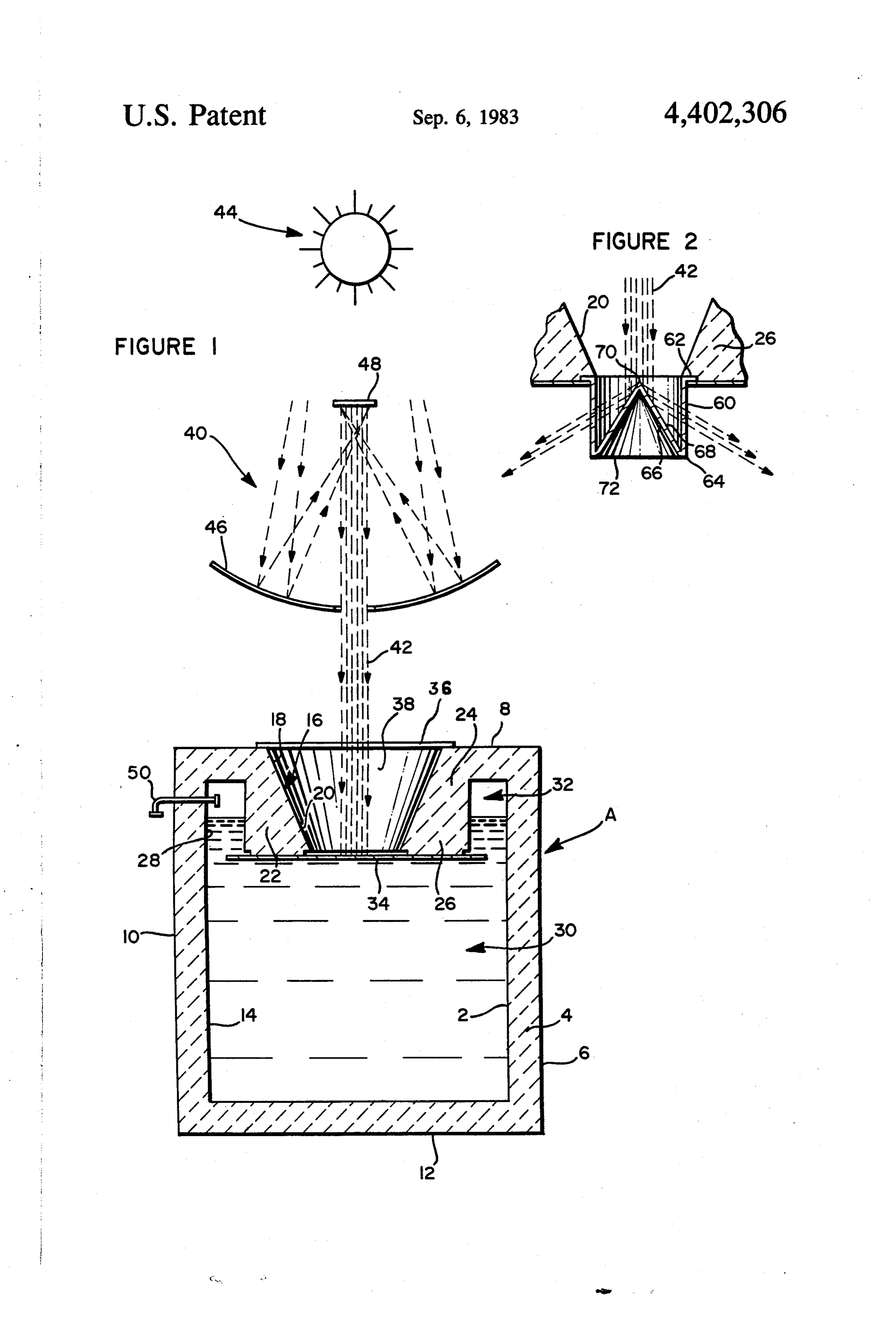
FIG. 2 is a fragmentary enlarged perspective view in
THERMAL ENERGY STORAGEMETHODS AND
PROCESSES
cross-section with the solar energy system and sun shown diagramatically.
FIELD OF INVENTION DETAILED DESCRIPTION OF THE
DRAWINGS
This application is a continuation-in-part of applica tion Ser. No. 134,501 filed Mar. 27, 1980, now aban Referring now to FIG. 1, the solar energy collecting doned. and storing device consists of a storage vessel desig This invention pertains to solar energy storage de nated by the letter A and including an inner shell 2, an vices and more particularly to solar energy storage 10 intermediate insulation layer 4, and an exterior shell 6 devices wherein concentrated solar energy is utilized in surrounding intermediate insulation layer 4. Inner shell order to heat a material having good heat absorbing and 2 may be constructed of steel, concrete, sheet metal, heat retaining capacity and wherein the heat absorbing reinforced glass fiber or other suitable material. Inter material is contained in a thermally insulated storage 15 mediate insulation layer 4 is preferably made of ceramic vessel of improved construction. fiber insulation. Exterior shell 6 may be constructed of HISTORICAL BACKGROUND reinforced glass fiber, sheet metal, aluminum or con crete.
With the increasing cost of conventional fuels such as Storage vessel A includes top wall 8, side walls 10 oil and natural gas, strong emphasis has been placed 20 and bottom wall 12. A heat retaining material holding upon research involving the use of solar energy as an chamber 14 is defined by walls 8, 10 and 12. alternative energy source. Solar energy has proven to A solar portal 16 having upper surface 18 and lower be a viable alternative to the more common energy surface 20 is formed in top wall 8 of vessel A. Solar sources presently in widespread use. The major criti portal 16 includes a tubular member 22 having upper cisms concerning the use of solar energy revolve 25 portion 24 and lower portion 26. Tubular member 22 around two major aspects, namely, the cost involved in extends from top wall 8 into heat retaining material manufacturing solar energy heating devices as well as holding chamber 14 and is spaced from side walls 10. the efficiency of those devices. For those reasons, wide The spacing between side walls 10 and tubular member spread use of solar heating apparatus has up to the pres 22 forms a second peripheral chamber 28 about solar ent time been thwarted. 30 portal 16.
SUMMARY AND OBJECTS OF THE Within holding chamber 14 is a material 30 having a INVENTION relatively low melting point as well as a good heat retaining capacity. This material is preferably paraffin,
This invention provides a device for effectively utiliz however other suitable materials may be used in place ing solar energy in order to transfer radiant heat to a 35 thereof. Material 30 substantially fills holding chamber medium possessing good heat absorbing capacity as 14 as well as a portion of second peripheral chamber 28 well as a specially designed thermally insulated storage so that it ultimately surrounds lower portion 26 of tubu vessel for the heat absorbing medium. lar member 22. Second peripheral chamber 28 includes The invention encompasses two embodiments, the an expansion area 32 above material 30 so as to permit first of which utilizes an indirect method for heating the material 30 to expand when heated. Possible anaerobic heat absorbing medium and the second utilizing means bacterial growth will be eliminated by the use of resid for directly heating the heat absorbing medium. ual pesticide.
It is therefore an object of the present invention to A sheet or plate of material 34 is associated with provide a solar energy collecting and storing device lower surface 20 of solar portal 16 in order to close having improved efficiency. 45 lower portion 26 of tubular member 22 and for transmit It is a further object of the present invention to pro ting energy to material 30. Sheet 34 may be metallic or vide a solar energy storage device which minimizes ceramic in nature. A sheet of transparent material 36 is thermal losses. associated with upper surface 18 of solar portal 16 in It is another object of the present invention to pro order to close upper portion 24 of tubular member 22. vide a solar energy collecting and storing device which 50 Transparent sheet 36 and heat transmitting sheet 34 is inexpensive to manufacture. are spaced a distance from each other so that a third It is a further object of the present invention to pro chamber 38 is formed therebetween. Third chamber 38 vide a solar energy collecting and storing device which provides for additional insulation of holding chamber utilizes either direct or indirect heating methods. 14 from the environment outside of vessel A. A still further object of the present invention is to 55 A solar concentrator 40 is positioned above solar provide a solar energy collecting and heating device portal 16 in order to direct concentrated solar rays 42 which is of rugged construction. from sun 44 through transparent sheet 36 and solar A still further object of the present invention is to portal 16 and on to energy transmitting sheet 34. Solar provide a solar energy collecting and heating device concentrator 40 is shown to include a parabolic dish 46 having domestic as well as commercial, industrial and 60 and a secondary reflector 48.
agricultural application. Leading into expansion area 32 of second peripheral The foregoing and other objects and advantages of chamber 28 is a pressure relief valve 50. An inert gas this invention will appear from the following detailed such as nitrogen or carbon dioxide may be added to description, taken in connection with the accompanying expansion area 32 in order to eliminate chemical drawings in which: 65 changes caused by oxidation of the heat storage liquid FIG. 1 is a cross-sectional view of the storage vessel 30 within vessel A.
with the solar energy system and sun shown diagramati Third chamber 38 is shown as being frusto conical in cally. shape.
Page 4
In the embodiment shown in FIG. 2, a generally including such departures from the present disclosure as cylindrical shaped transparent glass insert 60 is posi come within known or customary practice in the art to tioned by means of flange 62 within lower surface 20 of which this invention pertains, and as may be applied to solar portal 16 in order to close lower portion 26 of the essential features hereinbefore set forth and fall tubular member 22. Glass insert 60 extends into heat 5 within the scope of this invention or the limits of the retaining material 30 of holding chamber 14. Glass in claims.
sert 60 includes a base edge 64 which is positioned I claim:
below the surface of heat retaining material 30. A coni 1. A thermal energy collecting and storing device cal shaped member 66 having a mirrored exterior sur including:
face 68 is positioned within glass insert 60. Conical O (a) a thermally insulated storage vessel having top, shaped member 66 includes an apex 70 which points in bottom and side walls forming a heat retaining the direction of solar concentrator 40. Conical shaped materia' holding chamber, member 66 including apex 70 should be positioned (b) a solar portal having upper and lower surfaces below the surface of heat retaining material 30. Conical within said top wall, shaped member 66 also includes a base edge 72 which is 15 (c) said solar portal including a tubular member hav integrally formed with base edge 64 of glass insert 60. ing an upper and lower portion extending from said
OPERATION
top wall of said vessel into said heat retaining mate rial holding chamber and spaced from said side
Again referring to FIG. 1, this form of the invention walls of said vessel, provides means for indirectly heating heat retaining (d) said spacing between said side walls and said tubu material 30. Concentrated solar rays 42 emerging from lar member forming a second peripheral chamber solar concentrator 40 pass through transparent sheet 36 about said solar portal, and strike the upper surface of plate 34. Since the lower (e) a material having good heat retaining capacity and surface of sheet 34 is in direct contact with heat retain a relatively low melting point and substantially ing material 30, energy in the form of heat is transferred 25 filling said holding chamber and a portion of said through sheet 34 and into material 30. In order to mini second peripheral chamber and surrounding said mize thermal loss, storage vessel A is entirely insulated. lower portion of said tubular member, As material 30 is heated, it is allowed to expand into (f) said peripheral chamber including an expansion second peripheral chamber 28 and expansion area 32. If area above said heat retaining material to permit subsequent space for expansion is necessary, material 30 30 said material to expand when heated, may exit from the interior of vessel A through a pres (g) means associated with said lower surface of said sure relief valve 50 and into an exteriorly positioned solar portal for closing said lower portions of said secondary expansion vessel (not shown). tubular member and for transmitting energy to said With a relatively high specific heat and a wide stable heat retaining material, temperature range, paraffin is an ideal liquid medium in 35 (h) a transparent sheet associated with said upper which to store the thermal energy. surface of said solar portal for closing said upper In the embodiment shown in FIG. 2, direct heating of portion of said tubular member, material 30 is provided for. Concentrated solar rays 42 (i) said transparent sheet and said means associated emerging from solar concentrator 40 pass through with said lower surface being spaced from each transparent sheet 36 and through solar portal 16 and 40 other and forming a third chamber for insulating strike the surface of conical shaped member 66 which is said holding chamber from the outside of said stor positioned within the interior of glass insert 60. Since age vessel, and the exterior surface of conical shaped member 66 is (j) a solar concentrator positioned above said solar mirrored as shown at 68, incoming concentrated solar portal for directing concentrated solar rays rays 42 are reflected from surface 68 through the side 45 through said solar portal and onto said means for walls of insert 60 and subsequently into heat retaining transmitting energy.
material 30. The direct heating method of FIG. 2 is 2. A thermal energy collecting and storing device as somewhat more efficient than the indirect heating in Claim 1 and wherein;
method of FIG. 1. (a) said third chamber being frusto conical in shape. Thus, the energy collecting and storing device of this 50 3. A thermal energy collecting and storing device as invention is capable of storing vast amounts of energy in claim 1 and wherein;
whenever solar power is available. (a) said means associated with said lower surface of An alternative embodiment of the invention which is said solar portal for closing said lower portion of not shown would utilize a holographic lens system in 55 said tubular member and for transmitting energy to said heat retaining material including a sheet of conjunction with the apparatus previously described.
The thermal energy collecting and storing device heat absorbing and heat conducting material hav described above has application in domestic heating and ing a top surface and a bottom surface, cooling systems as well as in commercial, industrial and (b) said bottom surface being in contact with said heat agricultural processes. The potential usefulness of this retaining material, and system is enhanced due to its ability to produce steam. 60 (c) said top surface being exposed to said concen Production of steam will allow solar power to be trated solar rays.
readily adapted to existing commercial and industrial 4. A thermal energy collecting and storing device as machinery and processes. in claim 1 and wherein;
While this invention has been described as having a (a) said means associated with said lower surface of preferred design, it will be understood that it is capable 65 said solar portal for closing said lower portion of of further modification. This application, is therefore said tubular member and for transmitting energy to intended to cover any variations, uses, or adaptations of said heat retaining material including a generally the invention following the general principles thereof cylindrical shaped transparent glass insert posi
Page 5
tioned within said lower portion of said tubular (d) said conical shaped member including an apex member and extending downwardly into said heat pointing in the direction of said solar concentrator, (e) said apex located below the surface of said heat retaining material. retaining material, and (b) said glass insert having a base edge positioned (f) said conical shaped member including a base edge below the surface of said heat retaining material, integrally formed with said base edge of said glass (c) a conical shaped member having a mirrored exte insert.
rior surface positioned within said glass insert,
Provenance
- Collection
- Cited prior art
- Original PDF
- patentimages.storage.googleapis.com →
- Filed
- 1982-03-22
- Pages
- 5
- Method
- pdftotext (the PDF's own text layer) + pdftoppm 300dpi page scans
- Source
- Google Patents bibliographic record
- Granted
- 1983-09-06
- Inventors
- Robert C. McElroy, Jr.
- Transcribed from
- patentimages.storage.googleapis.com →