patent · US6314918
Renewable fuel generating system
13 November 2001
Page 1 — bibliographic record
(12) United States Patent (10) Patent No.: US 6,314,918 B1 McFarland et al. (45) Date of Patent: Nov. 13, 2001
(54) RENEWABLE FUEL GENERATING SYSTEM 4539,515 9/1985 Morishita et al. ..................... 32O/17 4,604,565 8/1986 Yokota et al. ... ... 320/15 (76) Inventors: Steve McFarland, 4101 W. Green Oaks 4,763,610 8/1988 Thomas .................................... 123/3 Blvd., #252, Arlington, TX (US) 76016; 4,788,486 11/1988 Mashino et al. ... 310/112 Wilbur Jones, 6735 Fire H1 Dr., Fort 5,159,900 11/1992 Dammann ................................ 123/3 Worth, TX (US) 76137 5,233,229 8/1993 Kohl et al. .... 307/10.1 s 5,254,936 10/1993 Leaf et al. .... ... 322/90 5,418,401 5/1995 Kaneyuki. 307/10.1 (*) Notice: Subject to any disclaimer, the term of this 5,424,599 6/1995 Stroud .............. ... 310/198 patent is extended or adjusted under 35 5,444,355 8/1995 Kaneyuki et al. ... ... 322/58 U.S.C. 154(b) by 0 days. 5,513,600 5/1996 Teves ....................................... 123/3 5,600,232 2/1997 Eavenson, Sr. et al. ... 322/12 (21) Appl. No.: 09/332,361 5,735.245 4/1998 Kebesh et al. ........... ... 123/417 9 5,739,676 4/1998 Judge et al. ..... ... 322/22 (22) Filed: Jun. 10, 1999 5,766,438 6/1998 Ishibashi et al. ... 204/520 7 5,779,866 7/1998 Tarancon .......... ... 204/262 (51) Int. Cl.' ...................................................... FO2B 43/08 5,833,821 11/1998 Schmid et al. . . 204/255 (52) U.S. Cl. ................................................................... 123/3 5,843.292 12/1998 Spiros .......... . . 204/258 (58) Field of Search ................................. 123/3, DIG. 12; 5,865,262 2/1999 Ni ........................................ 180/54.1
Primary Examiner Tony M. Argenbright (56) References Cited Assistant Examiner Hyder Ali
3,262,872 7/1966 Rhodes ................................. 204/272 This invention operates with Series of components inte 3,310,483 3/1967 Rhodes .... 204/268 grally connected to an internal combustion powered engine, 3,543,126 11/1970 Nolan et al. ... . . 320/39 wherein an OEM alternator supplies the various fixed volt 3,793,544 2/1974 Baumgartner . ...... 320/17 322/28 age load requirements of the engine and its accessories and
2Y-- - 2 f eSeele 320/64 additionally works in conjunction with a specifically
3,939,806 2/1976 Bradley .............. ... 123/3 designed high output electrical power generating device to 3,955,941 5/1976 Houseman et al. ... 48/95 energize a multiple cell anode and cathode type electrolyZer 3,980,053 9/1976 Horvath ......... ... 123/3 unit for liberating hydrogen gas to fuel Said internal com 4,014,777 3/1977 Brown. 204/228.5 bustion powered engine at greater than 100% efficiency 4,045,718 8/1977 Gray ....................................... 32O/17 levels. Various mechanical and electrical components are 4,081,656 3/1978 Brown ..... 219/137 incorporated to enhance fuel production, monitor and regu 4,088,450 5/1978 Kosaka et al. . ... 422/201 late System efficiency and Safety levels, and optimize the 3. E. WA, et al. . 2. performance of this renewable fuel generating System. 4,336,485 6/1982 Stroud ................ ... 320/15 4,517,507 5/1985 Nordbrock et al. ... ... 322/28 2 Claims, 2 Drawing Sheets
Page 2
Drawing sheet — no readable text.
Page 3
Drawing sheet — no readable text.
Page 4
RENEWABLE FUEL GENERATING SYSTEM a holding tank. Almost all of the water can be recovered and re-used indefinitely. The cooled air can also be re-used by
BACKGROUND-FIELD OF INVENTION recycling it back through the engine fuel intake. These are The present invention relates to renewable fuel Systems optional procedures which may not be advantageous for which supply greater than 100% of the fuel requirements for Some applications.but would most definitely be desirable for every application, internal combustion powered applications.
The practical application of the electrolysis method has
BACKGROUND DESCRIPTION OF PRIOR previously resulted in many less than Satisfactory attempts, ART primarily due to insufficient hydrogen gas production.
Because of the electrical power levels required to liberate
Various solutions have been set forth to improve the the hydrogen gas, this method can only be efficient if an quality of emissions in motor vehicles and other internal onboard power Supply is capable of furnishing ample current combustion powered applications due to environmental for adequate gas production.
concerns, as well as there being a general interest in the Another aspect that has challenged prior art has been technological development of more efficient and more eco 15 inadequate Safety measures due to the flammability of nomical energy Sources. hydrogen gas. AS with any combustible Substance, the Safe Among the methods being employed to achieve these use of hydrogen gas is a primary concern and reliable Safety goals are mechanical devices, chemical additives and alter measures must be included in the effective renewable fuel native fuels intended to reduce carbon monoxide, System for internal combustion engines. hydrocarbons, Sulfur compounds and other noxious emis In the current art we will set forth the techniques and Sions. Though there have been Some advancements resulting benefits from these efforts, Several problems Still persist, namely the making itfor Safety generating hydrogen fuel on demand, failure to completely and economically shrink toxic emis attractive. Thisenvironmentally both invention preferable and economically operates with a multiple-cell anode
Sions to Zero. With the exception of pure hydrogen, there is and cathode type hydrogen generator unit, coupled with no known alternative fuel which produces no toxicity in the 25 mechanical and electrical Safety controls, an automated combustion process. liquid level System, and an adapted fuel feed System. It also The use of hydrogen as an alternative fuel in internal includes a few modest modifications to the internal com combustion engines is both attractive and challenging. bustion engine in order for it to generate the electrical power Hydrogen is plentiful, non-polluting and renewable. Hydro required to produce greater than 100% of the hydrogen gas gen is non-toxic, non-corrosive and when used as a fuel, necessary to fuel internal combustion powered applications. reverts to harmless water vapor. Conversely, it is laborious It will further include the equipment changes necessary to isolate, Store and distribute on a large Scale. for the Safe and efficient utilization of hydrogen gas by the Chemical extraction, liquefaction and purification of internal combustion engine. These modifications, though not hydrogen on a large Scale requires elaborate cryogenics 35 extensive or excessively complicated, are integral and nec equipment, massive Storage facilities and extensive pipeline essary for the proper operation of the engine utilizing this networks. This method also presents the danger of trans type of fuel System.
porting highly preSSurized tanks of the Volatile material over Maintenance of the Renewable Fuel Generator System is roadways and railways. The end user also has the challenge minimal, requiring only a periodic addition of water, which of having to make more frequent fueling Stops or to install 40 can also be automated for most Stationary applications. larger fuel tanks because of the Volume of hydrogen gas Since the Systems can be installed and adapted to existing required per tank to fuel a 200 to 300 mile range. gasoline or alternative fuel type engines, rather than requir Though within the Scope and capabilities of industry, this ing new engine types, the fabrication, distribution, method should not be expected to Significantly reduce fuel installation, Service and repair of the Systems can be readily costs to the consumer because of the massive equipment, 45 assimilated into the marketplace by current means. perSonnel and distribution channel requirements involved. Therefore, for general use as a method of Supplying The concept of generating hydrogen gas on demand for renewable gaseous hydrogen fuel for most internal combus fuel consumption has the Safety and convenience advantages tion powered applications, the Renewable Fuel Generating of no need for refueling time, Storage tanks or equipment. System proves to be extremely advantageous. One method utilized to Supply hydrogen gas on demand has 50 been through the use of Solar energy panels to electrolyze OBJECTS AND ADVANTAGES liquid hydrogen compounds to liberate hydrogen gas. Accordingly, Several objects and advantages of the Obviously, this method only works when the Sun is shining. present invention make it unique and utilitarian. The System Another method of hydrogen gas production is the elec provides a continuous, economical and environmentally trolysis of hydrogen compounds Such as water to liberate 55 beneficial fuel Supply that is generated onboard the internal hydrogen gas for use as an alternative to fossil fuels. One combustion powered application, thus eliminating problems aspect that makes this method particularly attractive is that relative to hydrogen fuel production, Storage, distribution, it is capable of achieving an ultra pure hydrogen gas. The gas refueling, toxic exhaust emissions and the depletion of produced by this method is different from liquefied hydro natural resources.
gen gas in that it is a gas of Stoichiometric proportions, 60 The present invention increases the quality of liberated rendering two parts hydrogen and one part oxygen, which is hydrogen and oxygen gas available for fuel consumption the optimum mixture needed for combustion. over previous inventions which utilize an onboard electrical Upon combustion, the hydrogen and oxygen re-unite to power supply. The system provides over 100% of the fuel make water vapor, thus completing the renewal cycle to needed to run an internal combustion powered application, return the elements to their original State. Because of this 65 having adequate fuel pressure for the cycling on and off of unique characteristic, the exhaust vapors of the engine can the electrolyzer unit to allow cooling and to prolong the life be cooled down and the water condensed and redirected into of the System components. Higher renewable fuel produc
Page 5
tion from the eletrolyzer is achieved by a high output of some of the presently preferred embodiments of this onboard electrical power generating System. The fuel System invention. Various other embodiments and ramifications are is pre-pressurized by an AC power connection, which plugs possible within its Scope, Such as more powerful or leSS into normal household current, requiring only a few minutes powerful component parts, limiting devices and augmenting of time in the event of low fuel pressure before starting the devices which may be used to enhance the effects of the engine. Under normal operation conditions the System main present invention.
tains adequate fuel pressure for restarting. Thus, the scope of this invention should be determined by The electrical power generating System comprises an the appended claims and their legal equivalents, rather than OEM alternator, further including a plurality of electrical by the examples given.
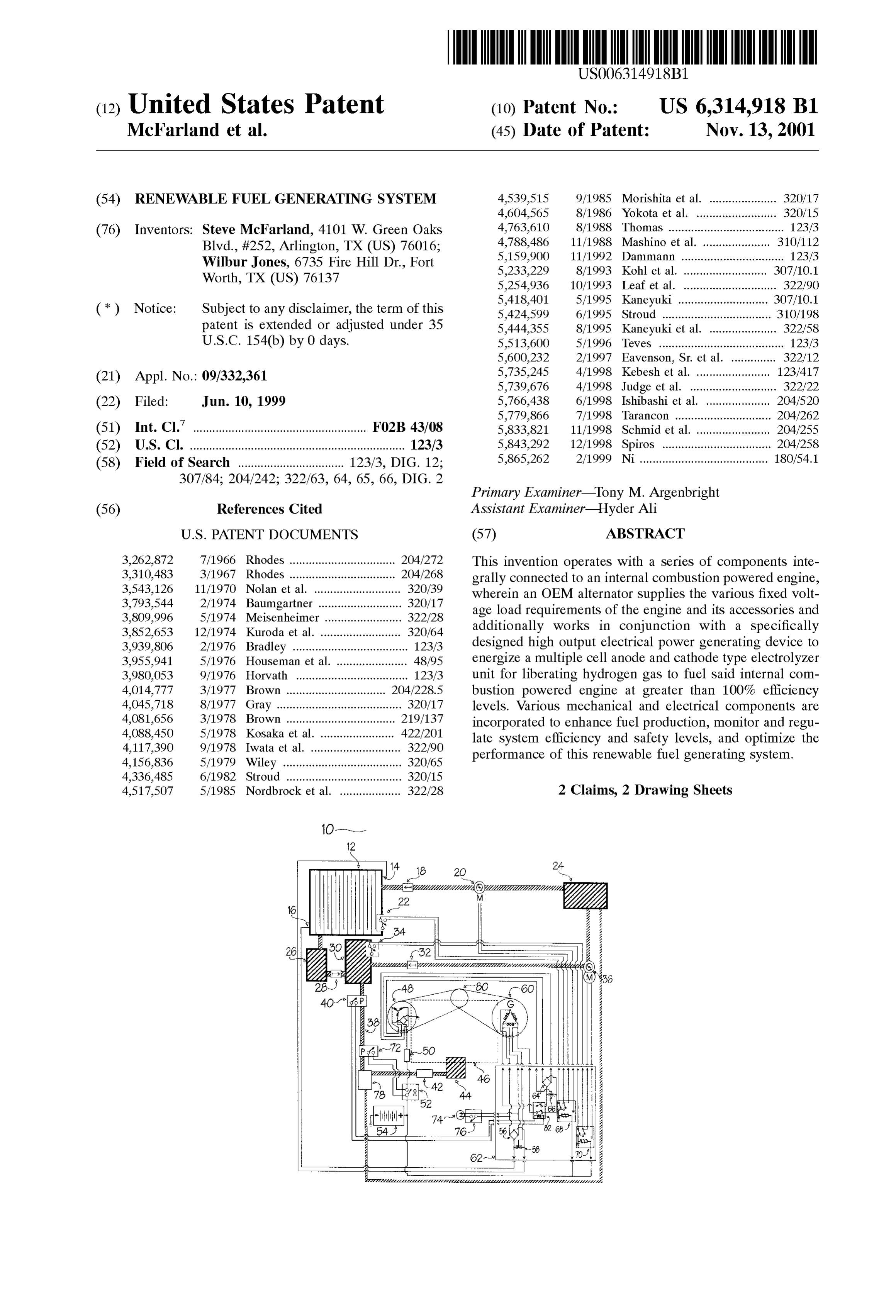
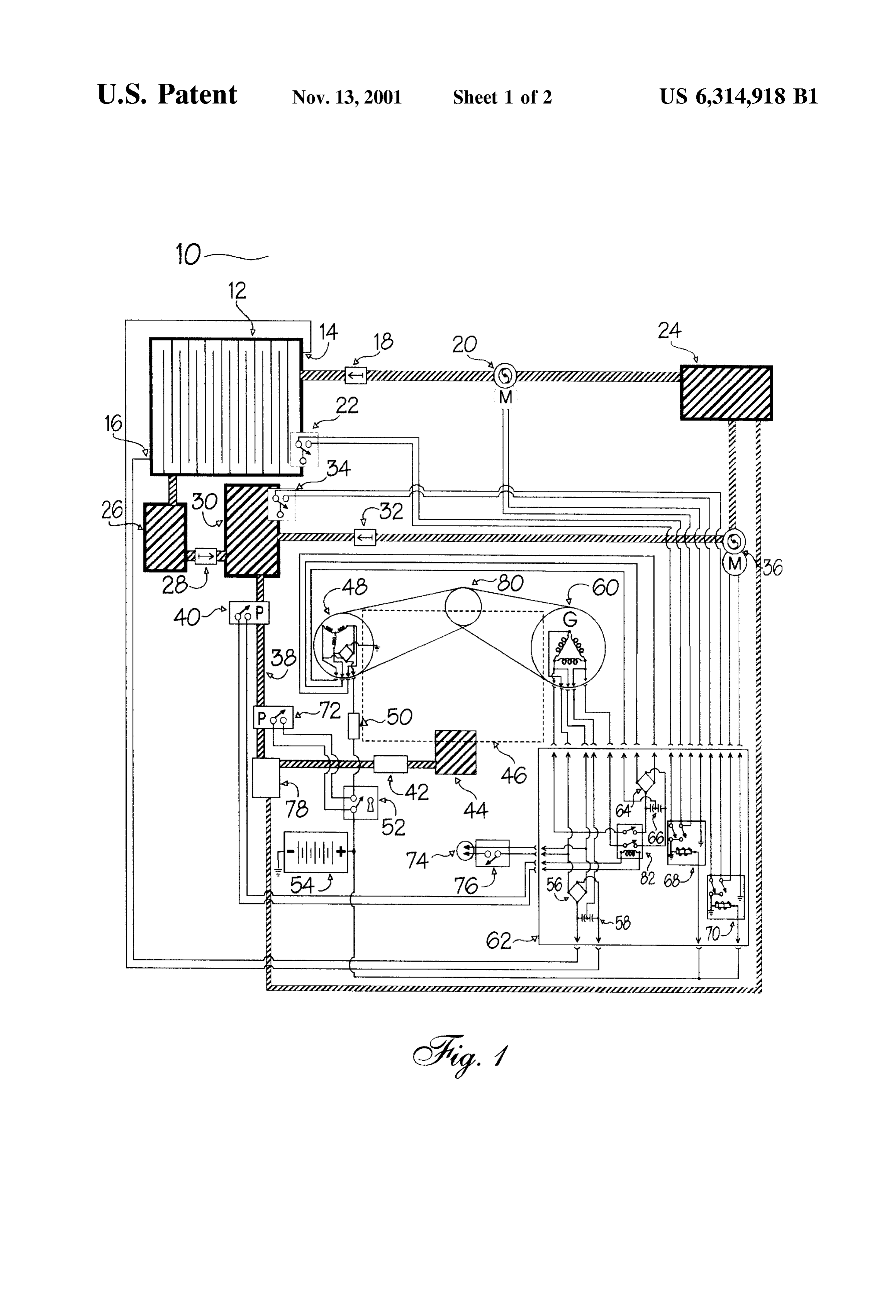
generating devices. The alternator is connected to a Voltage regulator to match the Specific Voltage output required by the BRIEF DESCRIPTION OF THE DRAWINGS Storage battery (or batteries), the engine's ignition System FIG. 1 is a layout of the Renewable Fuel Generating and its accessories. The System also includes at least one System with an electrical Schematic drawing of the compo Specifically designed high output electrical generating nents which Synergistically function to produce and regulate device, which is Serially connected to the alternator. The 15 the renewable hydrogen fuel as it is made ready to be used electromagnetic field generated by the OEM alternator and by the internal combustion powered engine, according to the additional electrical circuitry connected to the devices
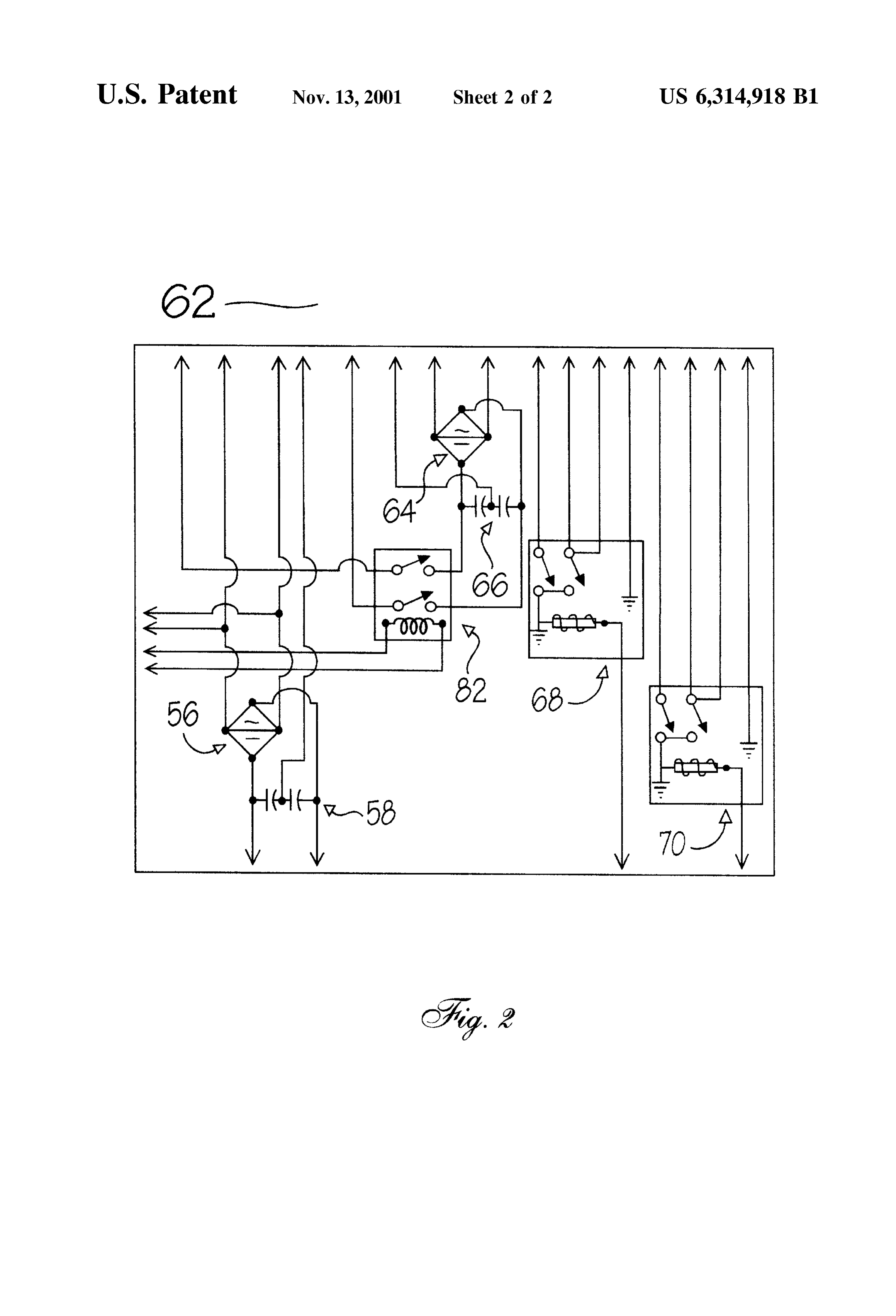
Works in conjunction with the power windings of the high oneFIG. embodiment of the present invention. output electrical generating device, allowing it to attain electrical2 isconnections, an enlarged electrical Schematic drawing of the rectifiers, capacitors, relays and much higher output levels than the alternator. The high Switches which are connected to the various electrical com output electrical generating device, as illustrated in the ponents of the renewable fuel generating System. current art, is thus uniquely dedicated to providing ample Reference Numerals:
current for the electrolyzer unit. The Second electrical gen erating device requires a minimal amount of horsepower 10-Renewable Fuel Generating System from the engine to generate electrical power. 25 12-Electrolyzer Unit 14-Anode Connection
The System further comprises water reservoirs, pumps, liquid level Sensoring and Switching devices, one way flow 16-Cathode Connection 18-One Way Flow Valve
Valves, a fuel line drying device, all carrying fuel and fluids 20-Electric in non-corrosive vessels to maintain the highest purity levels 22-Liquid Level Pump and minimize System parts deterioration. These accessories 24-Water Reservoir Switch provide automatic monitoring and Servicing of the renew 26-Separator Unit able fuel generator System to provide continuous, long lasting operation of the internal combustion powered appli 30-Gas 28-One Way Flow Valve cation. Diffuser Unit 35 32-One Way Flow Valve
A Superior level of Safety is achieved in the present 34-Liquid Level Switch invention over previous inventions in this field. This is 36-Electric Pump attained by a Series of Safety Switches, flash arresting devices 38-Fuel Line and techniques, Strategically applied for the purpose of 40-Pressure Switch restricting the flame of the hydrogen fuel within the com 40 42-Flash Arresting Device bustion chamber of the engine. AS illustrated herein, in the 44-Fuel Intake Controller event of a backfire, Safety measures are incorporated 46-Internal Combustion Powered Engine throughout the System to instantly extinguish any possible 48-OEM Alternator flame. Also, the system's safety level is further enhanced by 50 Voltage Regulator the absence of hydrogen fuel Storage tanks, which further 45 52-Ignition Switch removes the possibility of explosion or rupture in the event 54-Storage Battery of a Sudden impact. 56-Bridge Rectifier
Thus, Renewable Fuel Generator Systems, as configured 58-Capacitors above, afford definite advantages over previous art and other 60-High Output Electrical Generating Device environmentally oriented fuel enhancements, fuel alterna 50 62-Electrical Component Schematic tives and pollution control devices by economizing the 64-Bridge Rectifier quantity of equipment, fuel costs and Space requirements 66-Capacitors and by utilizing a renewable, recyclable fuel Source which 68-Latching Relay does not pollute and is not consumed in the combustion 70-Latching Relay proceSS. 55 72-Pressure Switch
Still further objects and advantages will become apparent 74-AC Power Cord from a consideration of the ensuing description and accom 76-On/Off Controller panying drawings. 78-Fuel Line Dryer Unit 80 Pulley
Conclusions, Ramifications, and Scope 60 82-On/Off Controller
Accordingly, it can be seen that the Renewable Fuel Preferred Embodiment-Description Generating System, as described above, Supplies more than adequate hydrogen fuel for an internal combustion powered Referring to FIG. 1, a Renewable Fuel Generator System engine and the normal load requirements of Said engine. 10 according to one currently favored embodiment of the Although the description above contains many 65 present invention will be described. The system includes a Specificities, these should not be construed as limiting the multiple cell Electrolyzer Unit 12 with an Anode Connection Scope of this invention but as merely providing illustrations 14 and a Cathode Connection 16. The liquid level of the
Page 6
S 6
Electrolyzer Unit 12 is maintained by a Liquid Level Switch tion. This disclosure should thus be considered illustrative, 22 which actuates an Electric Pump 20, transferring water not limiting. The Scope of this invention is instead defined by from a Water Reservior 24 through a One Way Flow Valve the following claims.
18 into the Electrolyzer Unit 12. What is claimed is:
The Electrolyzer Unit 12 Sends hydrogen gas through the 1. A renewable hydrogen gas fuel generating System for Separator Unit 26, a One Way Flow Valve 28, a Gas Diffuser internal combustion powered applications, Said System com Unit 30, then through a Fuel Line 38, a Pressure Switch 40 prising:
to maintain a specified fuel pressure, a Pressure Switch 72 to kill the engine in an over or under fuel pressure situation, a multiple cell anode and cathode type electrolyzer unit a Fuel Line Dryer Unit 78, a Flash Arresting Device 42, and wherein hydrogen gas and oxygen gas are liberated into the Fuel Intake Controller 44 of the Internal Combus from water molecules to provide more than 100% of tion Powered Engine 46. The liquid level of the Gas Diffuser the fuel required to operate an internal combustion Unit 30 is maintained by a Liquid Level Switch 34 which powered engine;
actuates an Electric Pump 36, transferring water from a an electrical power generating System wherein a low PRV Water Reservoir 24 through a One Way Flow Valve 32 into 15 alternator, connected at having power output windings the Gas Diffuser Unit 30. is circuited through a bridge rectifier and electrolytic The Electrolyzer Unit 12 is supplied electrical current capacitors to power windings of a specifically designed through a High Output Electrical Generating Device 60. high output electrical generating device, which electri This is accomplished when the rotations of the engine turn cal output is circuited through a high PRV high current a Pulley 80 which spin the belt-driven OEM Alternator 48 bridge rectifier and electrolytic capacitors to Supply and the belt-driven High Output Electrical Generating current to an electrolyzer unit for hydrogen gas pro Device 60. As they spin, current is discharged from the duction;
power windings of the OEM Alternator 48, through a Bridge a renewable fuel Supply System wherein the liberated Rectifier 56, Capacitors 58, and then connecting to the 25 hydrogen gas from Said electrolyzer unit is passed power windings of the High Output Electrical Generating through a gas Separator unit which allowS eXceSS liquid Device 60, through a Bridge Rectifier 64, Capacitors 66, to flow back into the electrolyzer unit while hydrogen passing through a Pressure Switch 40, and finally to the gas flows into a gas diffuser unit where it passes Anode Connection 14 and the Cathode Connection 16 of the through a porous barrier, is dispersed into a water bath Electrolyzer Unit 12. In the event of low fuel pressure upon and rises to enter a fuel line which passes through a starting the engine, an AC Power Cord 74 with an On/Off drying unit and a flash arresting device before being fed Controller 76 is included to plug into regular 110-120 VAC into a fuel intake controller, then ignited in a combus household current (or 220-240 VAC, where applicable) to tion chamber of an internal combustion powered pre-pressurize the fuel system. FIG. 2 displays the Electrical engine, which at one reverts to water vapor and is Component Schematic 62 which shows how the various 35 released through Said engine's exhaust System. electrical components of the Renewable Fuel Generating 2. A renewable hydrogen gas fuel generating System for System 10 are connected. internal combustion powered applications, as recited in The OEM Alternator 48 also supplies specific low voltage claim 1, wherein:
current through a standard Voltage Regulator 50, a key Said renewable fuel generating System is Supplied with operated Ignition Switch 52, a Storage Battery 54 to the low 40 ample current from a high output electrical power voltage loads of an Internal Combustion Powered Engine generating System to continuously produce greater than 46. Current is also supplied by the OEM Alternator 48 to 100% of an internal combustion powered engine's fuel operate the automated liquid level System, which comprises requirements, powering a multiple cell anode and cath two Latching Relays 68 and 70, two Liquid Level Switches Ode type electrolyzer unit which cycles on and off 22 and 34, and two Electric Pumps 20 and 36. 45 within a specified fuel pressure range by a preSSure Preferred Embodiment-Operation Switch to open and close a circuit from Said electrical power generating System;
In other embodiments of the present invention, diagnostic Said electrical power generating System having an OEM devices, meters, valves gauges, indicators, Switches, alternator which is capable of Simultaneously Supply regulators, filters, baffles, Surface coatings, heating and 50 ing regulated low Voltage electrical current for charging cooling Systems, exhaust recycling Systems, water distilla a storage battery, an ignition System and accessories, tion Systems, illuminators, encasements and enclosures, working in conjunction with the power windings of a insulating materials and other modifications and variations high output electrical generating device in order to will no doubt occur to those skilled in the arts to which this produce a high PRV high amperage necessary to power invention pertains. Such variations which generally rely on 55 Said electrolyzer unit.
the teachings through which this disclosure has advanced the art are properly considered within the Scope of this inven k k k k k
Provenance
- Collection
- Cited prior art
- Original PDF
- patentimages.storage.googleapis.com →
- Filed
- 1999-06-10
- Pages
- 6
- Method
- pdftotext (the PDF's own text layer) + pdftoppm 300dpi page scans
- Source
- Google Patents bibliographic record
- Granted
- 2001-11-13
- Inventors
- Steve McFarland; Wilbur Jones
- Transcribed from
- patentimages.storage.googleapis.com →