patent · US4081656
Arc-assisted oxy/hydrogen welding
28 March 1978
Page 1 — bibliographic record
United States Patent (19) 11) 4,081,656 Brown (45) Mar. 28, 1978 54 ARC-ASSISTED OXY/HYDROGEN (56) References Cited
WELDING
76) Inventor: Yull Brown, 182 Auburn Rd., 1,037,979 9/1912 Perkins .............................. 219/75 X 2,874,265 2/1959 Reed et al... ... 219/75 X
Auburn, New South Wales, 2,900,485 8/1959 Clark ...................................... 219/75 Australia 3,045,665 7/1962 Moyat ..... . 204/129 X 3,262,872 7/1966 Rhodes et al... . 204/129 X (21) Appl. No.: 722,125 3,310,483 3/1967 Rhodes ............................ 204/129 X Primary Examiner-Donald G. Kelly 22 Filed: Sep. 10, 1976 Assistant Examiner-K. J. Ramsey Attorney, Agent, or Firm-Hill, Gross, Simpson, Van
Related U.S. Application Data Santen, Steadman, Chiara & Simpson
4,014,777. This invention relates to welding, brazing or the like utilizing a mixture of hydrogen and oxygen generated in 30 Foreign Application Priority Data substantially stoichiometric proportions in an electro Jul. 20, 1973 Australia ............................... PB4159 lytic cell by electrical dissociation of water, the mixture so generated being passed from the generator through a
Aug. 3, 1973 Australia ............................... PB4341 flashback arrestor and thence to a burner where the May 2, 1974 Australia ............................... PB7418 gases are ignited. The invention also relates to atomic welding in which the above mentioned mixture is (51) Int. C.2 ...................... B23K 17/00; C25B 15/02; passed through an arc causing dissociation of both the C25B 1/04 hydrogen and oxygen into atomic hydrogen and oxy (52) U.S. C. ................................. 219/137.31; 219/75; gen which on recombination generate an intensely hot 219/121 P; 228/242; 431/2; 431/11 flame.
219/137 R; 431/2, 11; 204/129 17 Claims, 7 Drawing Figures
H2 * O2 uuuu
GENERATOR
O ARC
GENERATOR
Page 2
Drawing sheet — no readable text.
Page 3
Drawing sheet — no readable text.
Page 4
Drawing sheet — no readable text.
Page 5
Drawing sheet — no readable text.
Page 6
The practice of using bottled gas also has associated
ARC-ASSISTED OXY/HYDROGEN WELDING with it a large number of other problems such as the This is a division of application Ser. No. 489,921 filed possibility of gas leaking from bottles, possibility of July 19, 1974, now U.S. Pat. No. 4,014,777. industrial disputes which can result in severe delays in This invention relates to welding, brazing and the 5 delivery and in supply shortages, liabilities, high pur like, utilising hydrogen and oxygen, and extends to such chase and storage costs, freight charges, and so on. applications as oxy-welding, oxy-cutting, atomic weld To illustrate some of the conditions which the con ing, and welding or cutting in combination with electric Sumer of bottled gas must put up with, listed below is a arc techniques. The invention also provides for the summary of the "conditions of sale" which apply to the generation of hydrogen and oxygen for the abovemen 10 sale and distribution of bottled gas. tioned applications in combination therewith or sepa (a) The cylinder remains the sole property of the rately. supplier, which retains the right to exercise at any time A most important application of the invention is its proprietory powers in its discretion. atomic welding utilising the properties of atomic oxy (b) All cylinders and contents are forwarded at the gen in combination with atomic hydrogen (for welding) 15 expense and risk of the customers. or atomic oxygen separately (for cutting). This particu (c) It is the responsibility of the customers to provide lar application of the invention is based, among other adequate labour for the loading and unloading of all things, on the appreciation that considerable energy is cylinders at the premises. v . .. associated with the dissociation of molecular oxygen (d) Cylinders are to be returned to the supplier as into atomic oxygen by passing this gas through an arc, 20 soon as empty, carriage and freight charges paid. and that this property can be usefully employed to gen (e) A cylinder is not "returned' until received by the erate temperatures even higher than those previously supplier at its works or warehouse or by its truck and a attainable with, for example, an atomic hydrogen flame. receipt of the suppliers form given for the same. No The significance of the energy which can be obtained in document purporting to be a receipt for any such cylin this way can be appreciated from the following reac 25 der shall be valid unless it is the suppliers printed form tions that take place, and the heat energies associated of receipt, therewith, when hydrogen and oxygen are both passed (f) Cylinders are not transferable and must not be through an electric arc. Thus: used for any purpose other than as containers for the gas sold by the supplier and must not be delivered or sent 30 for recharging to any place other than the suppliers gas
H - H -- H absorbing 101,000 cal. per gram mole station.
(g) The customer agrees not to resell to any person or total 218,000 cal. per gram mole
Corporation, the gas contents of the cylinders of any part thereof,
On recombination of these atoms this energy is re 35 (h) Customers are held responsible for all loss or leased as heat through a number of complex chemical damage to cylinders from whatever cause arising from reactions and results in an extremely high flame temper the time of delivery until returned to the suppliers. ature. Previously it would not have been considered (Customers are advised to cover the cylinders by insur possible to practically pass oxygen or a mixture of oxy ance), gen and hydrogen together through an arc due to the 40 (i) Where a customer has not returned a cylinder in highly explosive or inflammable nature of such gases. good order and condition within six months from the However in accordance with the concepts of the pres date of delivery, the supplier may, at it's option, charge ent invention this is indeed both possible and practical the customer with an amount not exceeding the agreed and, as mentioned above, enables the realisation of value of the cylinder and the demurrage due in respect much higher welding or cutting temperatures than hith 43 thereof, and such amount is payable by the customer as erto obtainable by known practical means. liquidated damages for the detention of the cylinder. One of the objects of the present invention is to pro Notwithstanding the payment of such amount in respect vide a method and apparatus whereby hydrogen and of any cylinder, it remains the property of the suppliers oxygen can be generated quickly and conveniently for and the right of the suppliers to recover possession immediate use for welding, etc., without many of the SO thereof is not affected in any way. disadvantages associated with conventional gas welding (i) No allowance is made on any residual gas returned practice, For example, the practice of employing cylin in the cylinders, ders (or "bottles') of gas, usually oxygen and acetylene (k) And many other conditions varying in the differ can have significant disadvantages, particularly for ent countries in the world.
users working remote from a supply depot and for 55 Another disadvantage, which is associated with ox whom there might be an appreciable delay between the y/hydrogen welding arises due to the marked ability of placing of an order for a delivery of gas the the actual hydrogen to be absorbed by most metals. Thus when delivery, For such users, in order to ensure an adequate welding steel, for example, great care must be taken to supply of gas when a particular job demands it, it is ensure that excess hydrogen is not present otherwise it often necessary to order fresh supplies in advance, even will be absorbed in the metal to cause loss of strength before the supply on hand is fully used, or else risk and brittleness. On the other hand, an excess of oxygen running out of gas before a job is completed. Since would cause burning of the metal and should thus bottles of gas are generally delivered on a strictly ex equally be avoided. It is most important therefore that change basis - in that a used bottle must be returned in with oxy/hydrogen welding the mixture at the burner exchange for a refilled bottle - the practice can mean 65 be adjusted to produce a neutral flame, that is, one in a significant waste, as far as the user is concerned, if which there is neither excess hydrogen nor excess oxy bottles containing useful amounts of unused gas have to gen. In practice it is most difficult to maintain (and be returned to the supplier. virtually impossible to judge by flame colour) a neutral
Page 7
flame, and for that reason oxy/hydrogen welding is not in which both hydrogen and oxygen can be mixed widely used despite the inherent advantages of low cost within the cell, and in which cells can be connected in and high heat value offered by hydrogen as a fuel. series, parallel, or parallel and series to suit require These and other disadvantages can be overcome to a Inents.
significant extent by the present invention whereby (i) The choice of materials for the electrodes. hydrogen and oxygen fuel are generated simultaneously () The quantity of acids or alkali to be used. by electrolysis in an electrolytic cell and allowed to (k) The shapes of cells according to purpose of the freely mix therein to form a stoichiometric mixture that cells, and the application for which they are designed. will burn with a neutral flame. The fuel gas can be (l) The possibility of improvement with permanent or generated where and whenever required thereby elimi O electro-magnetically induced fields applied to the elec nating the need for storage of bottles of gas and reliance trolytic cells, to cause controlled separation of a quan on regular deliveries of gas which often cannot be guar tity of the gases generated in the cells. anteed. (m) Ensuring effective circulation of electrolyte be The method of the present invention requires no tween the electrodes, with as little electrical resistance diaphragms or the like to separate the hydrogen and 15 possible.
oxygen liberated by the electrolysis process and thereby as (n) The possibility of using sodium hydroxide or po enables considerable advantages to be realised over conventional electrolytic production of these gases. tassium up to hydroxide which, in concentrations from 10% 30%, which has negligible corrosion action on
Such diaphragms have normally been regarded as es sential for conventional electrolytic generators in order 20 iron or nickel electrodes, apart from producing a solu to separate the two gases that would otherwise form a tion(o)ofThe good conductivity.
use of the cooling effect by passing of hydro highly explosive mixture; however, it has been found, in gen and oxygen gases, for cooling electrolyte in the cell, accordance with the present invention, that the two for controlling the cell temperature, preferably between gases can be safely, and usefully, produced and utilised as a mixture for fuel purposes provided that suitable 25 40' C to 60 C, at which temperature the bonds between safety precautions, such as the employment of a flash hydrogen and oxygen need a minimum of electrical back arrestor, are taken. Such safety precautions may energy to break.
include, for example, the employment of a device which (p) The separation of hydrogen and oxygen from a removes electrolyte vapour from the gas and at the mixture, using, possibly, a permanent magnetic field, or same time acts as a flash-back arrestor. In obviating the 30 an electro-magnetic field which can be controlled to need for diaphragms or the like the present invention obtain a desired separation between the hydrogen and enables the electrodes to be placed much closer to oxygen. Based on this principle, the oxygen could be gether and avoids the high resistance associated with substantially separated from the mixture and the hydro diaphragms, which in turn enables a significant increase gen could be absorbed by, for example, selected metals, in the rate of gas production for a given size of appara 35 which have high absorption affinity for hydrogen (for tus. In short the present invention enables the manufac example, paladium which absorbs 900 times more hy ture of small size equipment that is useful for a large drogen from its volume). Also, using the principle of the variety of welding and similar work and that is not invention, hydrogen and oxygen can be generated in prohibitively bulky for the average situation: something large quantities with small units and the oxygen could, which is impossible with conventional hydrogen/oxy for example, be separated and used to supply hospitals, gen generating equipment. baby rooms, air conditioning systems, or for any other In the development of apparatus from the basic con application, when oxygen is required. Oxygen can, in cept of generation of hydrogen and oxygen electrolyti this way, be generated much faster and more conve cally in a practical manner suitable for large industrial niently than with conventional electrolytic generating applications on the one hand, and small domestic appli 45 equipment, cations on the other hand, a number of factors had to be (q) The possibility of absorbing the hydrogen or oxy taken into account, analysed and weighed one against gen by specially selected materials in small containers the other. The following is a list of some of these factors and where the absorbed gas can be extracted when to illustrate what has been involved.
(a) Endosmotic pressure to be balanced against the 50 desired venient for welding or brazing where it would be incon or impossible to do so with conventional equip hydrostatic pressure of the fluid.
(b) Rate of flow of electric current in relation to the ment.(r) Making the welding operator entirely independent area of the electrodes.
(c) The prior art problem of removing the gases from of any gas suppliers.
anolyte and catholyte, before diffusion and before the 55 times The (s) generation or cheap gas, up to six to seven cheaper than normal gas supplies.
electrolytes are intermixed. (t) The design of equipment which gives not only (d) Effects of rapid changes in the rate of flow of professional welders, but handymen, or people who electricity through the cell.
(e) Effects of auxiliary decomposition within the would like to do welding at home with oxy-welding anode and cathode sides of the cell. apparatus, but would do it only occasionally and could (f) The choice of the most readily ionised electrolyte not justify the expense associated with conventional gas of a maximum conductivity. supplies. Such people cannot justify paying for bottles (g) The least possible spacing between anode and of gas for a single welding only (having to keep the cathode that can be employed. bottles, paying rent for them to keep them up to two (h) A design of cell in which previously it was re 65 years, to perform the next welding). For this reason, the garded impossible for the H2 and O, given to become welding apparatus made possible by the present inven mixed with safety, which does away with diaphragms tion is ideal because it produces gases for welding at the or the like which would increase the internal resistance, time and in the quantity that is needed.
Page 8
(u) Hydrogen/oxygen welding has the advantage small welding and brazing work but for larger work that it does not pollute the atmosphere as does oxy/ace (for example, the welding of 10 mm steel plate) the tylene welding. required amperage becomes excessive (typically of the (v) The design of electrolytic cells which are safe to order of 900A or more) when considering the size of use as well as convenient, which cells may incorporate conductors and transformer and the problem of heat their own flash-back arrestors as a safety precaution or generation. Accordingly, in one aspect of the invention an equivalent means, to prevent the hazards of explo these problems can be significantly reduced by arrang sion or fire. ing a plurality of cells in series and using a much smaller (w) The control of the current which passes through current to obtain the same effective gas output. In effect the cells, the temperature of the cell, which is a function 10 the capacity of a series of cells for a given current input of current, the control of the separation of the gases, is that of a single cell multiplied by the number of cells. and the removal from the gases of electrolyte vapours. Alternatively the current requirement is reduced by a In this regard there has been designed a special unit factor equal to the number of cells - for a given rate of with preferably conical electrodes, and a flash-back gas production.
arrestor. The flash arrestor may be constituted by a 15 Even so a large number of separate cells can be exces pellet of porous material, or a long capilliary pipe lo sively bulky for portable applications and in a further cated between the gas generator and a burner head. The aspect of the invention, therefore, the bulk can be fire hazards associated with a mixture of hydrogen and greatly reduced by arranging the cells as a single unit in oxygen cannot be over-emphasised and indeed it is which a number of electrodes, effectively in series, are probably mainly because of the recognised dangers 20 arranged adjacent each other in a common electrolytic associated therewith that extreme lengths have been chamber, the chamber being provided with a gas collec taken to separate the two gases completely until they tion space and an outlet for connection to, for example, reach the burner. In accordance with the present inven gas burner means. Furthermore, only the end electrodes tion it has been realised that, contrary to long standing need be connected to an external source of electrical opinions, the gases can be safely mixed together even 25 energy and the arrangement as a whole can be made when being produced and as a result many desirable extremely efficient and compact. Additionally the need advantages can be realised. for a transformer for most applications can be elimi (x) The provision of one or more safety valves ad nated by such an arrangement so that the apparatus can justed to convenient pressure for releasing excessive be designed to be electrically connected directly to a pressures in the cell (for example, greater than 30 p.s. i.) 30 main electrical supply, through a bridge rectifier if de which may result, for example, if a current control sired. By eliminating the need for a transformer, the gas mechanism fails. The safety valves could be attached to generating equipment as a whole can be made surpris an alarm, for example, to indicate a failure in the current ingly compact, to be well suited for small domestic control mechanism or the cut-off switches, etc. requirements as well as heavy industrial requirements. (y) Porous material may conveniently be placed in 35 In another important aspect of the invention, there is the burner head, so that backfire through the burner provided a safety device which monitors the pressure of into the cell cannot occur. the hydrogen and oxygen being generated and regulates In summary, the present invention contemplates, as the current flowing through the cell(s) to increase or an important feature thereof, a universal welding appa decrease the rate of gas production depending on the ratus capable of being used to perform different types of 40 pressure. In one form the device comprises a chamber welding operations based on the utilisation of hydrogen containing two electrodes, at least one of which is coni and oxygen, making full use of the advantages which cal, arranged in the chamber (which normally contains can thereby be realised, and equipment which can be a conductive liquid) and the electrodes being connect made small and portable compared with existing appa able in series with one or more electrolytic cells used for ratus such as that presently used for gas welding using 45 oxygen/hydrogen production.
bulky bottled hydrogen. To generate the fuel, in accor The pressure responsive, current regulating device dance with the invention a small compact electrolytic can be designed as an integral part of the electrolytic cell is made possible in which the only raw material cell(s) or can be used as an attachment connectable which has to be replenished from time to time is water externally and in series with the gas generating cell(s). and which can be used whenever a source of electrical 50 The device can also be designed to combine the func energy is available to supply the necessary amount of tions of a current regulating device and a flash-back hydrogen or hydrogen and oxygen mixture for per arrestor, the latter function ensuring that a flame at the forming atomic welding or hydrogen/oxygen flame burner does not accidentally pass back through the hose welding. In its simplest form, the gas generating appara lines to the highly explosive mixture in the gas generat tus of the present invention comprises an electrolytic 55 ing cell(s). The device may incorporate a total current cell adapted to be connected to an energy source, op cut-out feature or may be used in combination with a tionally through a step down transformer and rectifier, cut-out device which fully interrupts the supply of elec and having means for connection to a burner, preferably trical power should the pressure in the cell(s) acciden through a flashback arrestor as a safety precaution. tally exceed a maximum safe value. The current regulat The apparatus may be combined with a transformer ing device may also operate to regulate the current as a single compact unit and for convenience the trans passing through the cells in accordance with the tem former may be provided with several windings to en perature to maintain the temperature within a desired able it to be used for auxiliary purposes such as battery range.
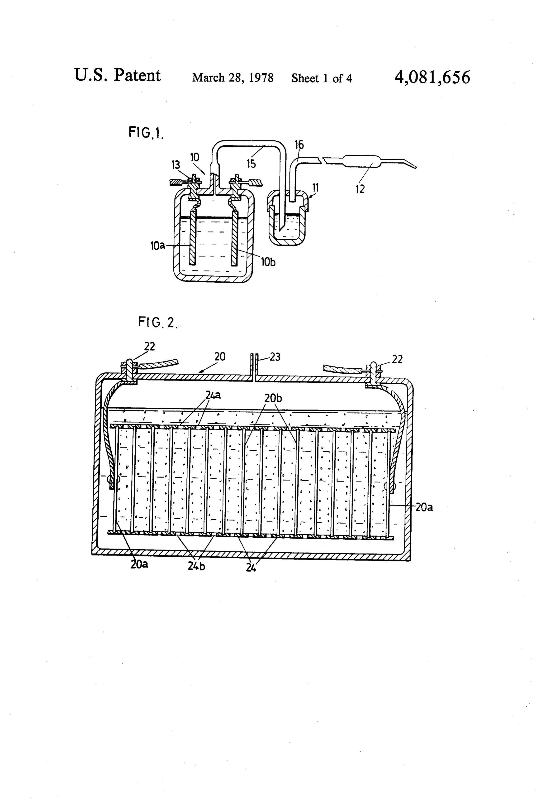
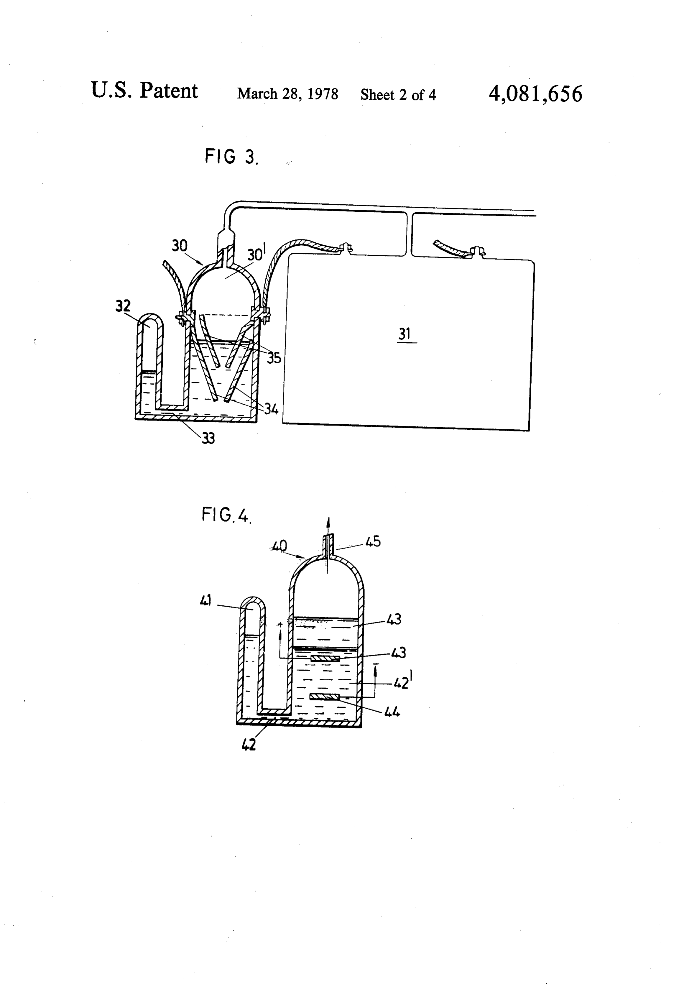
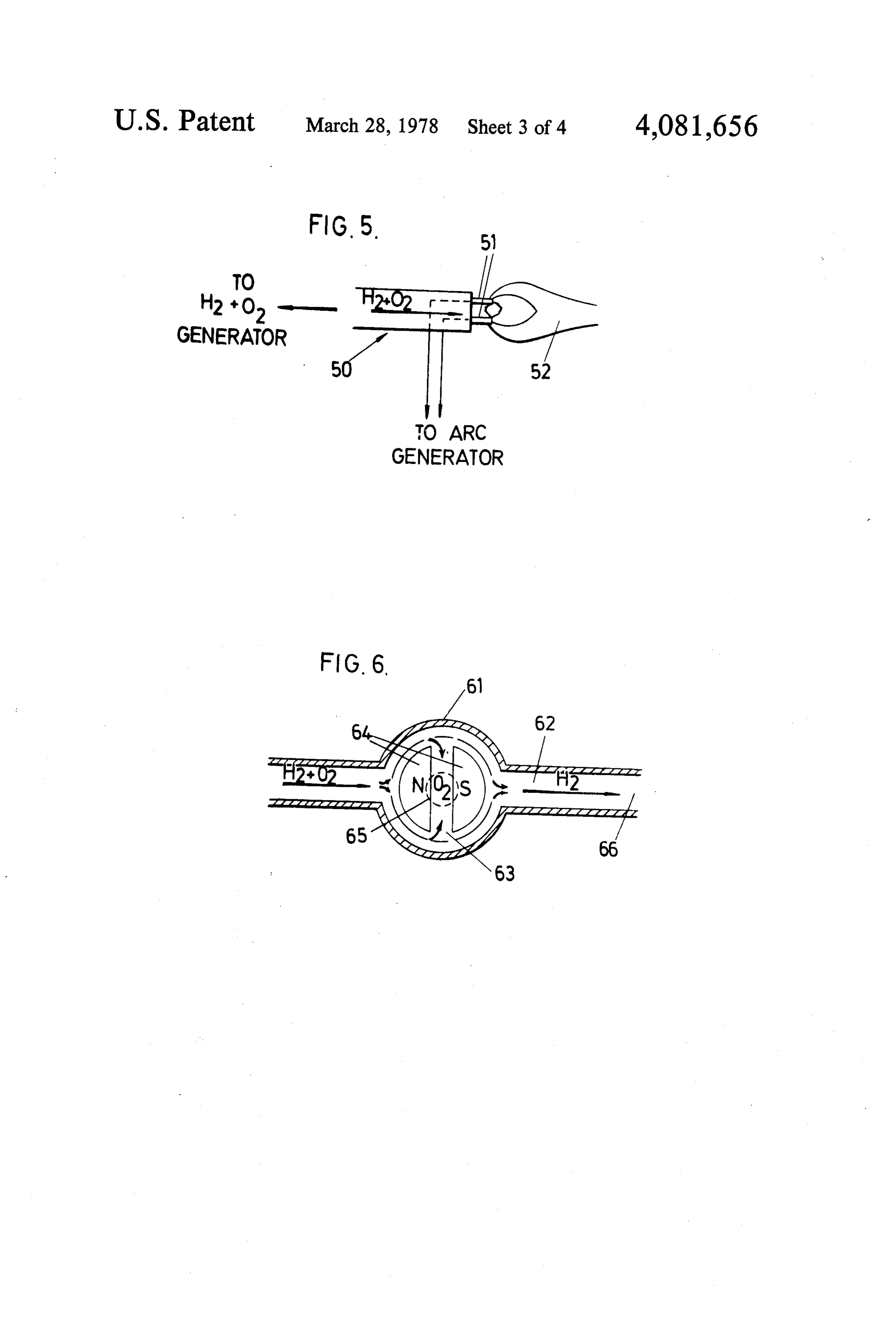
charging, electroplating, arc welding or to provide an Referring to the drawings, arc for atomic welding. 65 FIG. 1 is a schematic view of an embodiment of the It has been found that a single electrolytic cell operat invention, ing without diaphragms at several hundred amps will FIG. 2 is a cross-sectional view of an electrolytic cell generate hydrogen and oxygen at a reasonable rate for used in the invention,
Page 9
FIG. 3 is a view partly in section of a pressure respon cally produced in substantially the correct proportions sive regulator for a electrolytic cell, to give a neutral flame. No mixing valves are required FIG. 4 is a cross-sectional view of a modified pres and even unskilled personnel can produce satisfactory sure regulator, welds without difficulty. In fact indications are that FIG. 5 is a schematic diagram of the torch operation, many welds can be produced better than by any other FIG. 6 shows a magnetic gas separation device, and welding process.
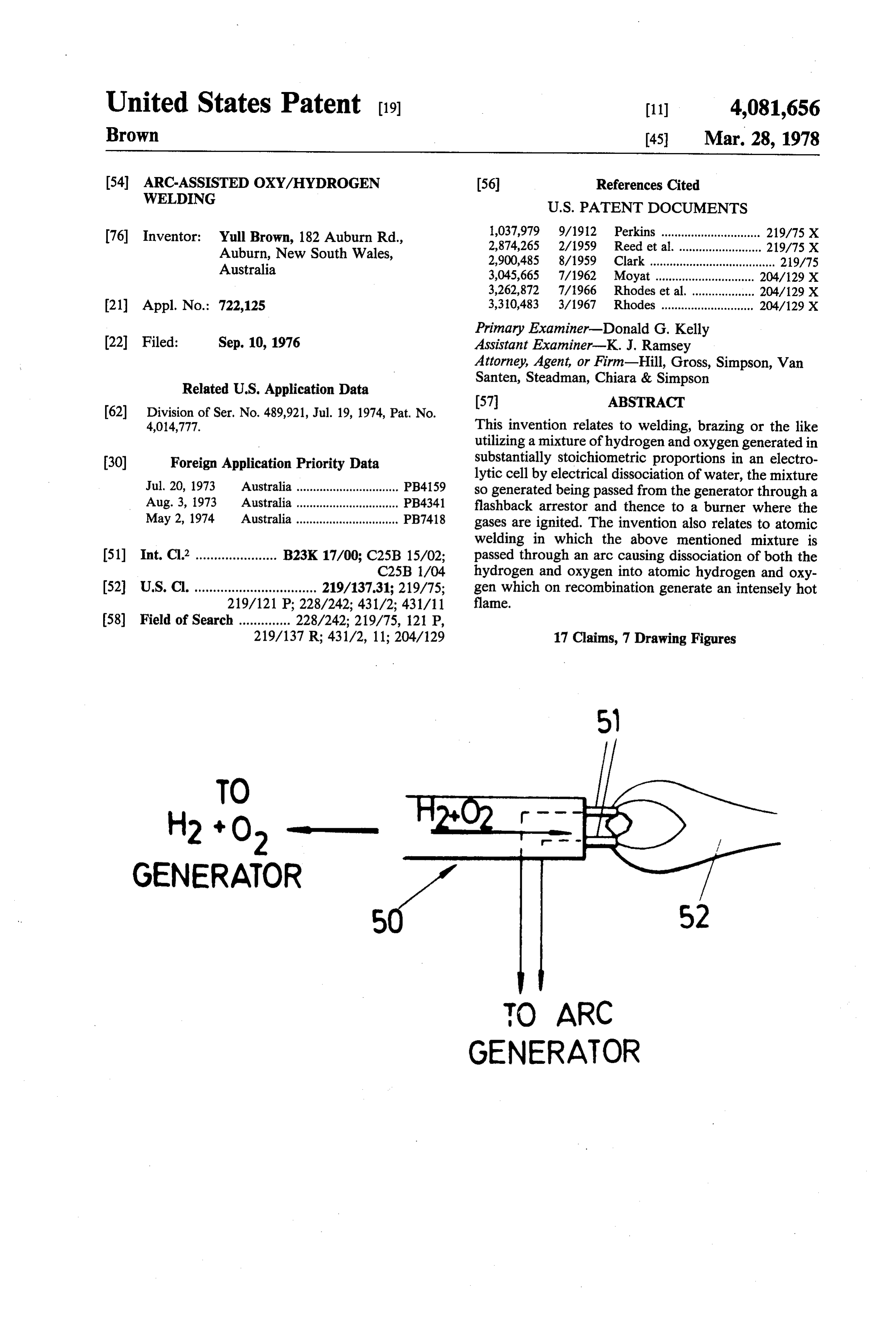
FIG. 7 is a detailed schematic view of another em FIG. 3 illustrates a pressure responsive safety device bodiment of the invention. 30 operably connected in series (electrically) with an Referring to the drawings, FIG. 1 shows schemati electrolytic hydrogen/oxygen cell 31 for regulating the cally a single electrolytic cell 10 operating to produce a O current passing therethrough in accordance with the mixture of hydrogen and oxygen, which mixture is gas pressure being generated. The device, or cell 30 passed through a flash-back arrestor 11 to a burner 12. comprises a chamber 30' in communication with a reser The cell 10 contains two plate electrodes 10a and 10b voir 32 via a passage 33. Two conical electrodes 34 and immersed in an electrolyte consisting of a solution of 35 are mounted in spaced relation within the chamber KOH in water and connectable through terminals 13 15 and connected in series between a digsource (not and 14 respectively to a source of a.c. or d.c. electricity. shown) and the electrolytic cell 31. Ah s Preferably, d.c. is used as the electrical impedance of solution of KOH and water is provided within the the cell, is much lower for d.c. than for a.c. The source chamber, portion of which enters the reservoir 32. of electricity may be a transformer, typically of 300 When the cell 31 is operating to produce hydrogen and Amps output rating, connected to the cell through a 20 oxygen the pressure of the gas being produced acts on bridge rectifier. The flash-back arrestor 11 is constituted the surface of the electrolyte in the chamber 30" to by a water bath in which gas liberated in the cell 10 displace an amount of the electrolyte into the reservoir passes through a tube 15 into the water bath 11 and 32 against back pressure exerted by air trapped in the thence through a tube 16 to the burner 12. The arrange reservoir, the amount of electrolyte displaced depend ment is suitable for small welding and brazing work but 25 ing on the pressure of the gas in the chamber 30'. At the becomes too bulky for very large work. same time the area of contact between the electrodes FIG. 2 illustrates in vertical cross-section an electro and the electrolyte in the cell 30 reduces in proportion lytic cell 20 which requires a much lower current than to the drop in electrolyte level, causing the electrical the cell illustrated in FIG. 1 for a given current input. resistance of the cell 30 to rise and the current passing The cell 20 comprises what is in effect a series of cells 30 therethrough to fall. Should the gas pressure drop the constituted by a plurality of plate electrodes immersed electrolyte level in the cell 30 will rise and the current in a solution of KOH in water. For convenience the passing into the cell 31 will also rise. Thus the cell 30 electrodes are designated as 20a for the two electrodes operates to regulate the rate of gas production in accor at the ends and 20b for the intermediate electrodes. The dance with the pressure produced and prevents excess electrodes 20a are connected, via conductors 21 to ter 35 gas pressure to build up in the cell 31. minals 22 for connection to an external supply of elec FIG. 4 illustrates an alternative form of safety device tricity. The mixture of hydrogen and oxygen which is which is operable to make or break the connection evolved at the electrodes when an electric current is between an electrolytic hydrogen/oxygen cell (not applied, passes through an outlet opening 23 to a flash shown in FIG. 4) and an electric current source. The back arrestor and thence to a burner (not shown in FIG. device comprises a cylindrical container 40 in fluid 2). The series of electrodes 20a and 20b are sealingly communication with a liquid reservoir 41 via a passage mounted in a tube 24 of insulating material which is way 42, and a quantity of mercury (42') contained in the provided with restricted apertures 24a at the top and container and reservoir. Two electrodes 43 and 44 are 24b at the bottom, between each pair of electrodes. The disposed one above the other in the container 40 and are apertures 24a permit gas to. escape into the space 25 45 normally immersed in the mercury with a conductive above the surface of the electrolyte and the apertures path thereby formed between them. The container is 24b permit electrolyte to enter freely into the spaces connected electrically in series with an electrolytic cell between each pair of electrodes. By virtue of this ar (or cells) and in gaseous communication therewith rangement the electrical resistance between any two through a hose 45. An increase in gas pressure resulting adjacent electrodes is for less than that between non 50 from generation of gases by the electrolytic cell(s) adjacent electrodes so that the arrangement is effec causes the mercury to be displaced towards the reser tively one of a large number of individual cells con voir and the mercury level in the container 40 to fall. nected in series. A very compact arrangement is there When the pressure exceeds a predetermined level the fore obtained but one which permits a relatively high mercury level falls below that of the electrode 43 and gas production rate for a reasonably low current input. 55 electrical connection between the two electrodes is For example, a structure like that shown, consisting of broken. The electrical connection is again restored the equivalent of, for example, 120 cells can generate when the gas pressure falls. A non-flammable liquid, gas at a current input of 15A (at, for example, 240V) such as silicone oil or freon is provided on top of the equal to that of a single cell requiring a current input of mercury to ensure that any arc which may be generated approximately 1800A. This means in practice that a 60 between the electrode 43 and the mercury is totally relatively portable apparatus can be produced which isolated from the gases above the liquids. can be connected directly, without a transformer, to FIG. 5 shows schematically an arrangement whereby most domestic electrical supplies and which can main an exceedingly hot flame can be produced using the tain a sufficient rate of gas production for most types of gaseous mixture generated electrolytically by the appa welding work. 65 ratus previously described. In this arrangement a mix An advantage which particularly distinguishes the ture of hydrogen and oxygen, preferably in stoichiomet arrangements disclosed from conventional gas welding rical proportion, is passed via a line 50 between a pair of apparatus is that the hydrogen and oxygen are automati tungsten electrodes 51 to produce molecular dissocia
Page 10
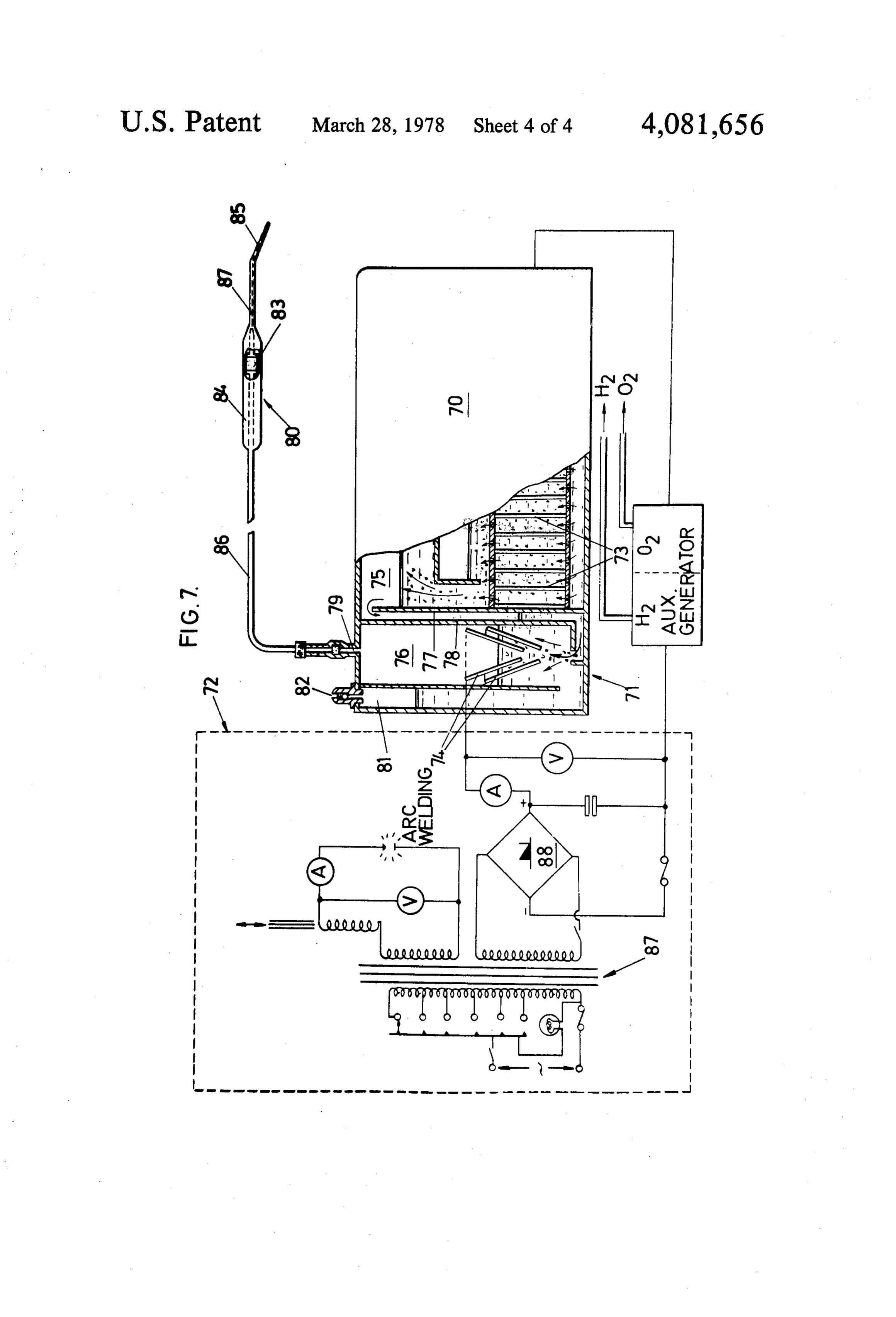
tion of the hydrogen and the oxygen and a very hot fore the flame has a chance to reach the hose 86 con flame 52. It can be appreciated that whereas in an necting the burner with the gas generator. atomic hydrogen flame a significant temperature rise is The power supply is of the universal type, that is, it is obtained by striking an arc in the hydrogen, an even provided with a transformer 87 connectable to an alter greater temperature rise can be realised by striking the nating current electrical supply and provided with a arc between the oxygen as well since the dissociation number of electrical outlets for various purposes. One energy of molecular oxygen is of the same order of winding of the transformer is connected to a bridge magnitude as that of molecular hydrogen. rectifier which provides the d.c. current for the gas FIG. 6 illustrates an arrangement for the magnetic generator. Another winding is used for arc welding or separation of oxygen from a mixture of oxygen and O can be used to supply an arc for atomic oxy-hydrogen hydrogen, whereby the oxygen can be used for flame welding. It will be appreciated that the transformer is cutting. The apparatus consists of a chamber 60 contain optional and that the generator can be connected di ing a magnet 61 and located in a conduit 62. A mixture rectly to the mains. In fact the bridge rectifier is not of hydrogen and oxygen is passed through the conduit essential either and can be omitted if desired. and around the magnet 61. The diamagnetic oxygen is 15 In the operation of apparatus of the type described it diverted by the magnetic field into a transverse passage is often required to conveniently change between neu way 63 to a central conduit (not shown) leading from tral and oxidising flames, for example when changing this passageway and thence to a flame-cutting head. from a welding operation to a cutting operation and the The paramagnetic hydrogen continues along the con present invention makes provision for the variation of duit, past the magnet and can be allowed to escape or these functions. Briefly, in accordance with the present can be collected, as desired. If the magnet is an electro invention, apparatus for either oxy-hydrogen welding magnet it can be turned off when hydrogen and oxygen or cutting may comprise a first electrolytic generator is required as a mixture, and in that case the downstream for generating hydrogen and oxygen by the electrolysis side of the conduit 62 can be closed off to prevent the of water in substantially stoichiometric proportions to loss of gas. 25 produce a neutral flame and a further electrolytic gener FIG. 7 illustrates a complete oxy-hydrogen genera ator from which hydrogen and oxygen are separately ting/welding apparatus comprising a gas generator 70, a delivered, with means for adding either the hydrogen current regulating cell 71 and a power supply 72. The from this further cell, or the oxygen from the further construction of the electrodes 73 of the generator 70 generator to the gas mixture obtained from the first and 74 of the cell 71 are identical with those illustrated 30 generator. This arrangement results in a most efficient in FIGS. 2 and 3 respectively. In this arrangement, combination of functions when a neutral flame or other however, the gas generator 70 and cell 71 are combined is required. The hydrogen gas produced by the further as an integrated unit and as such has some features not generator, when added to the flame mixture, burns with found in the arrangements shown in FIGS. 2 and 3. In atmospheric oxygen thereby producing a reducing particular the chamber 75 of the generator 70 and the 35 flame. When an oxidising flame is required, the addi chamber 76 of the current regulator cell 71 are sepa tional hydrogen is cut off and the oxygen produced by rated by two partitions 77 and 78 defining between them the further generator is added to the flame mixture. It a passageway communicating between the two cham will be appreciated that various designs can be em bers. The respective electrodes of the cell 71 and gener ployed for either generator, for example, they may be ator 70 are connected electrically in series with the completely independent or they may share a common power supply. electrolyte. The further gas generator can also, in prac Gas produced by electrolysis in the chamber 75 rises tice, be made somewhat smaller than the other genera into the space in the chamber above the electrodes 73, tor since it does not have to produce the bulk of the gas passes down the passageway between the partitions 77 required.
and 78, bubbles through the electrolyte in the chamber 45 It has been found that welding with hydrogen and 76 and thence passes through an outlet opening 79 to a oxygen in an exact 2 to 1 ratio (as when the gases are burner 80. An air trap reservoir 81 is formed integrally produced electrolytically) results in a particularly with the cell 71 and is in liquid communication there clean, oxide free welded surface and a strong welded with through an opening between the bottom of the joint. For the same quality welding to be produced by reservoir and the cell. When the pressure of the gas 50 conventional gas welding technique substantially generated by the generator 70 rises, this pressure causes greater skill is required and, in the case of conventional the electrolyte in the chamber 76 to be displaced into hydrogen welding, for example, good welded joints are the reservoir 81 resulting in a reduction of the current obtained only with great difficulty due to the extreme being passed to the generator 70 by the mechanism difficulty in obtaining and maintaining a neutral flame. previously described in relation to FIG.3 of the draw 55 With the method of the present invention there is no ings. In this way the cell 71 effectively monitors the gas difficulty in obtaining a neutral flame, and hence the pressure and regulates the current to maintain an ap ease with which high quality welds can be obtained. proximately constant pressure. To ensure against the Finally, it can sometimes be convenient to store hy possibility that the pressure should accidentally exceed drogen and/or oxygen, generated electrolytically in a a predetermined maximum safe value, a spring-loaded specially designed container, or to slowly accumulate safety pressure valve 82 is provided at the top of the these gases and then, when required, using the accumu reservoir 81 to release the excess pressure into the atmo lated stored gas for extra heavy work for a short time. sphere. It is quite hazardous to pressurise a mixture of hydrogen The burner 80 is provided with a flash-back arrestor and oxygen under very high pressures, of course, but it in the form of a porous ceramic pellet 83 located in the is possible, in accordance with one aspect of the inven gas flow path between the handle part 84 of the burner tion, to store a useful amount of gas in a relatively small and the burner tip 85. The flash-back arrestor acts by volume at low pressures and this can be done by using quenching any flame blowing back into the burner be a highly gas absorbent metal in the storage container.
Page 11
The metal palladium, for example, can absorb up to 900 lytic chamber having electrodes immersed in an aque times its own volume of hydrogen and can be used with ous electrolyte contained in said chamber, a pressure advantage for this application. In fact useful amounts ofsensitive regulating device containing an aqueous elec hydrogen, for small scale brazing work can readily be trolyte, at least one pair of electrodes immersed in the stored in a small hand held container, containing a gas aqueous electrolyte contained in said regulating device absorbent material. and connected in series with said electrodes contained I claim: in said at least one electrolytic chamber, a passageway 1. A method of oxy/hydrogen welding, brazing or connecting said pressure sensitive regulating device the like, characterized by electrolytically generating a with said at least one electrolytic chamber, said aqueous mixture of hydrogen and oxygen in substantially stoi 10 electrolyte in said pressure sensitive regulating device chiometric proportions by passing an electric current being displaceable relative to said pair of electrodes between electrodes immersed in an aqueous electrolyte immersed therein so as to proportionately increase the contained in at least one electrolytic chamber, passing electrolyte resistance between said pair of electrodes the mixture of hydrogen and oxygen from said at least and consequently reduce the electric current passing in one chamber through an aqueous electrolyte contained 15 series between said pair of electrodes and said elec in a pressure sensitive regulating device having at least trodes in said at least one electrolytie chamber in accor one pair of electrodes connected electrically in series dance with an increase in pressufe of said gases, at with said electrodes in said at least one electrolytic outlet to said regulating device, means passing said chamber, which electrolyte in said regulating device is gaseous mixture from said outlet through a flash back displaceable as a result of pressure of said mixture of arresting means to a burner nozzle, and a pair of elec hydrogen and oxygen to proportionately increase the trodes arranged downstream of said burner nozzle in electrolyte resistance between said pair of electrodes the path of said gases therefrom, said electrodes being and consequently reduce the electric current passing between said pair of electrodes in said regulating device connectable causing to a source of electrical arc energy for dissociation of said gaseous mixture into atomic and said electrodes in said at least one electrolytic 25 chamber in accordance with an increase in pressure hydrogen and atomic oxygen.
10. Apparatus as claimed in claim 9, wherein said at therein, passing said gaseous mixture through falshback least one electrolytic chamber comprises a plurality of arresting means and thence through a burner nozzle, electrolytic producing an arc between electrodes arranged down ries parallel cells connected electrically in series or se and arranged each to generate a mixture of stream of said burner nozzle and in the path of said gases 30 hydrogen and oxygen by electrolytic dissociation of so as to produce dissociation of said gases into atomic said aqueous electrolyte.
hydrogen and atomic oxygen, and burning said hydro gen and oxygen to produce a flame, the temperature of 11. Apparatus as claimed in claim 10, wherein the the flame exceeding the normal temperature of combus plurality of electrolytic cells is constituted by a plurality tion of molecular hydrogen and oxygen. 35 of electrodes arranged in close-spaced relation in a man 2. Method as claimed in claim 1 wherein excess oxy ner to be effectively in series or series parallel the elec gen is added to the mixture of hydrogen and oxygen and trodes at each end of the series being connectable the flame is used for metal cutting. through terminals to a source of electrical energy. 3. Method as claimed in claim 1 wherein said electric 12. Apparatus as claimed in claim 11, wherein the current is passed through a plurality of electrolytic cells electrodes.comprise a series of parallel plates mounted connected electrically in series, the hydrogen and oxy in spaced relationship along an insulated tube and in gen liberated in each cell being collected as a stoichio sealing relationship therewith, with apertures being metric mixture which is passed through said pressure formed in the tube between each pair of adjacent plates sensitive regulating device. to provide for passage of electrolyte into the space 4. Method as claimed in claim3, wherein the plurality 45 between each pair of plates, and the escape of gas there of electrolytic cells is constituted by a plurality of elec from.
trodes arranged side-by-side in an electrolytic bath in a 13. Apparatus as claimed in claim 9, including means manner to be electrically in series, with the electrodes at for the separation of oxygen from a mixture of hydro each end of the series being connectable with an exter gen and oxygen and passing the oxygen so separated as nal source of electrical energy. 50 excess oxygen to the burner head. 5. The method of claim 3, further characterized by 14. Apparatus as claimed in claim 13, wherein said using an A.C. supply in combination with a transformer means comprises a passageway for the passage of a to provide the electrical currrent for the cells. mixture of hydrogen and oxygen, means for producing 6. Method as claimed in claim 3, wherein additional a magnetic field in the passageway, to separate the hy hydrogen and oxygen are generated separately in a 55 drogen and the oxygen, and means for collecting either further electrolytic cell or cells and the additional hy of the hydrogen or oxygen so separated. drogen and/or oxygen so generated is/are added to the 15. Apparatus as claimed in claim 9, wherein a safety said mixture of hydrogen and oxygen before the mix pressure release valve means is provided in combination ture is passed through said arc. with pressure sensitive regulating device to release gas 7. Metal cutting according to claim 6, wherein the pressure therefrom when exceeding a pedetermined additional oxygen is obtained by magnetic separation value.
thereof from a mixture of hydrogen and oxygen. 16. Apparatus as claimed in claim 9, including trans 8. The method as claimed in claim 1, wherein the arc former means in combination therewith for arc welding, welding is accomplished by the use of an electrical battery charging, supply of current of the electrolytic transformer. 65 cells or the like.
9. Apparatus for the generation of hydrogen and 17. Apparatus as claimed in claim 9, including a oxygen and utilization of same for welding, brazing or bridge rectifier in circuit with the electrolytic cell(s). the like, said apparatus comprising at least one electro
Provenance
- Collection
- Cited prior art
- Original PDF
- patentimages.storage.googleapis.com →
- Filed
- 1976-09-10
- Pages
- 11
- Method
- pdftotext (the PDF's own text layer) + pdftoppm 300dpi page scans
- Source
- Google Patents bibliographic record
- Granted
- 1978-03-28
- Inventors
- Yull Brown
- Transcribed from
- patentimages.storage.googleapis.com →