patent · US3262872
Apparatus for the electrolytic production of hydrogen and oxygen for the safe consumption thereof
26 July 1966
Page 1 — bibliographic record
July 26, 1966 W. A. RHODES ETAL 3,262,872
APPARATUS FOR THE ELECTROLYTIC PRODUCTION OF HYDROGEN AND
OXYGEN FOR THE SAFE CONSUMPION THEREOF
Filed March 23, 1962 6 Sheets-Sheet
H N N g 3
s O LL O H O O c orra 2 w area
gu R 9 g sea Sl re (r 2 to Z1
ElL
n W of n
INVENTORS
By RAYMOND A. HENES
Page 2
July 26, 1966 W. A. RHODES ETAL 3,262,872
APPARATUS FOR THE ELECTROLYTIC PRODUCTION OF HYDROGEN AND
OXYGEN FOR THE SAFE CONSUMPTION THEREOF
Filed March 23, 1962 6 Sheets-Sheet 2
INVENTORS
WILLIAM A. RHODES,
By RAYMONDA, HENES
Page 3
July 26, 1966 W. A. RHODES ETA 3,262,872
APPARATUS FOR THE ELECTROLYTIC PRODUCTION OF HYDROGEN AND
OXYGEN FOR THE SAFE CONSUMPTION THEREOF
Filed March 23, 1962 6 Sheets-Sheet 5
INVENTORS
AA 4. RAYMOND A HENES
Page 4
Drawing sheet — no readable text.
Page 5
July 26, 1966 W. A. RHODES ETAL 3,262,872
APPARATUS FOR THE ELECTROLYTIC PRODUCTION OF HYDROGEN AND
OXYGEN FOR THE SAFE CONSUMPTION THEREOF
Filed March 23, 1962 6 Sheets-Sheet 5
WILLIAM A. RHODES,
BY RAYMOND A. HENES
Page 6
Drawing sheet — no readable text.
Page 7
United States Patent Office 3,262,872 Patented July 26, 1966
combination of hydrogen and oxygen generator; a recti 3,262,872 fier for supplying energy to the generator and a bleed-off APPARATUS FOR THE ELECTROLYTIC PRODUC pressure regulator for controlling pressure of the mixture TION OF HYDROGEN AND OXYGEN FOR THE of hydrogen and oxygen and oxygen passing from said
SAFE CONSUMPTION THEREOF
William A. Rhodes and Raymond A. Henes, Phoenix, generator; a blower disposed to force a draft of air over Ariz., assignors to Henes Manufacturing Co., Phoenix, said rectifier for cooling the same disposed to force air Ariz., a corporation of Arizona over said bleed-off pressure regulator to dilute the excess Filed Mar. 23, 1962, Ser. No. 182,726 mixture of hydrogen and oxygen bled therefrom, to there 10 Claims. (Cl. 204-272) by render said bleed-off mixture non-combustible. 10 Another object of the invention is to provide a very
This application is a continuation-in-part of a co-pend compact generator for electrolytic production of hydrogen ing application of William A. Rhodes, Serial Number and oxygen which is provided with novel extended sur 108,164, filed May 5, 1961, and now abandoned, for face area anode and cathode structure formed of concen Means and Method for the Electrolytic Production of Hy tric tubular members whereon annular surfaces are pro drogen and Oxygen for the Safe Consumption Thereof. 15 vided with circumferential ridges and grooves. This invention relates to a means and method for the Another object of the invention is to provide a novel electrolytic production of hydrogen and oxygen and for generator for electrolytically producing hydrogen and the safe consumption thereof, by a torch or other means oxygen wherein a very simple float structure readily in controlling the combustion of these gases.
It has been a problem to utilize a mixture of hydrogen 20 sible bytheremoving dicates fiuid level in the generator and is readily acces a filler cap from a filler neck through and oxygen in a torch and particularly so when hydrogen which water may be added to the electrolyte in the gen and oxygen is produced electrolytically and delivered in erator.
a common conduit to such a torch. The explosion haz Another object of the invention is to provide a novel ards of this mixture of gases have been difficult to alleviate. generator for electrolytically producing hydrogen and Additionally, it has been a problem to control the pro 25 oxygen wherein a novel frame heat sink structure Supports duction quantity of hydrogen and oxygen, and to dispose the generator and other components thereof including an of excess of these gases without creating a hazardous A.C.-D.C. power supply means which also dissipates heat condition. Furthermore, a simple, economical and relia to the frame and heat sink structure, of the invention. ble arrestor for use in stopping combustion of these gases, Another object of the invention is to provide a novel as it flashes back from a torch toward the generator of 30 generator for electrolytically producing of hydrogen and such gases, has been very difficult to develop.
Accordingly, it is an object of the invention to provide oxygen which delivers a mixture of hydrogen and oxygen through a novel tank of methyl alcohol or equivalent ma a means for electrolytically producing a mixture of hy terial whereby such material is entrained in the mixture of drogen and oxygen from water and to conduct the mix hydrogen and oxygen and may be burned to reduce the ture directly to a torch for combustion thereof, without 35 oxygen content in the area of the flame and at a high the hazard of dangerous explosions. temperature cone of a torch and around an area of ma Another object of the invention is to provide novel means for resisting flame travel, in a balanced mixture of is not being terial welded so that such material, when welded, readily oxidized.
hydrogen and oxygen from a torch to a production source Another object of the invention is to provide a novel of hydrogen and oxygen. 40 generator for the production of hydrogen and oxygen and
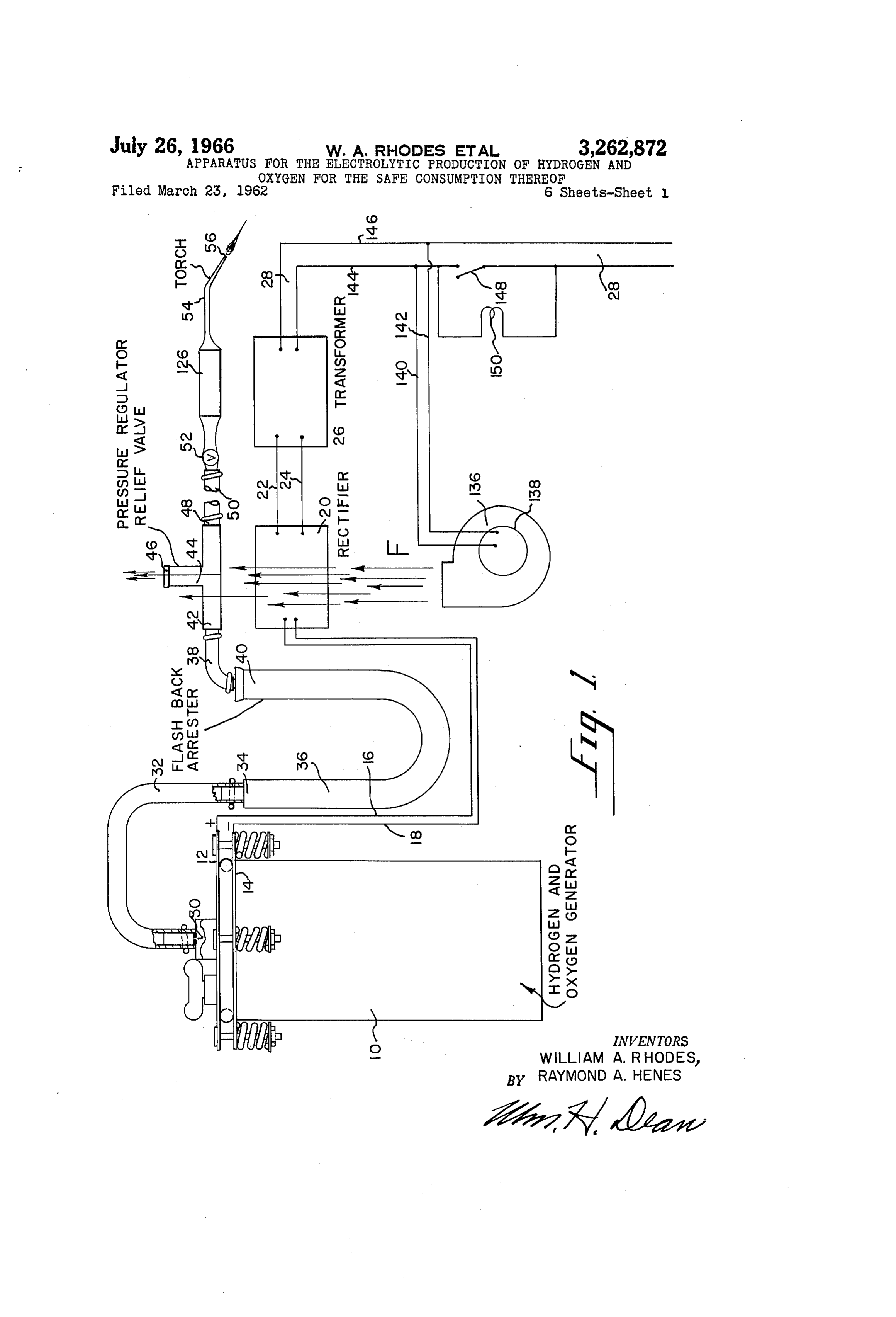
Another object of the invention is to provide means for means coupled thereto to provide for an increase in the electrolytically producing hydrogen and oxygen, having a B.t.u. output of a hydrogen and oxygen flame which is bleed-off pressure regulator disposed in the path of a forced air draft which dilutes the excess production of fed from the generator of the invention. 45 Further objects and advantages of the invention may hydrogen and oxygen combustible in the atmosphere. be apparent from the following specification, appended Another object of the invention is to provide a novel bleed-off pressure regulator for use in handling various claims and accompanying drawings, in which: FIG. 1 is a diagrammatic view of an electrolytic hydro compressible fluids.
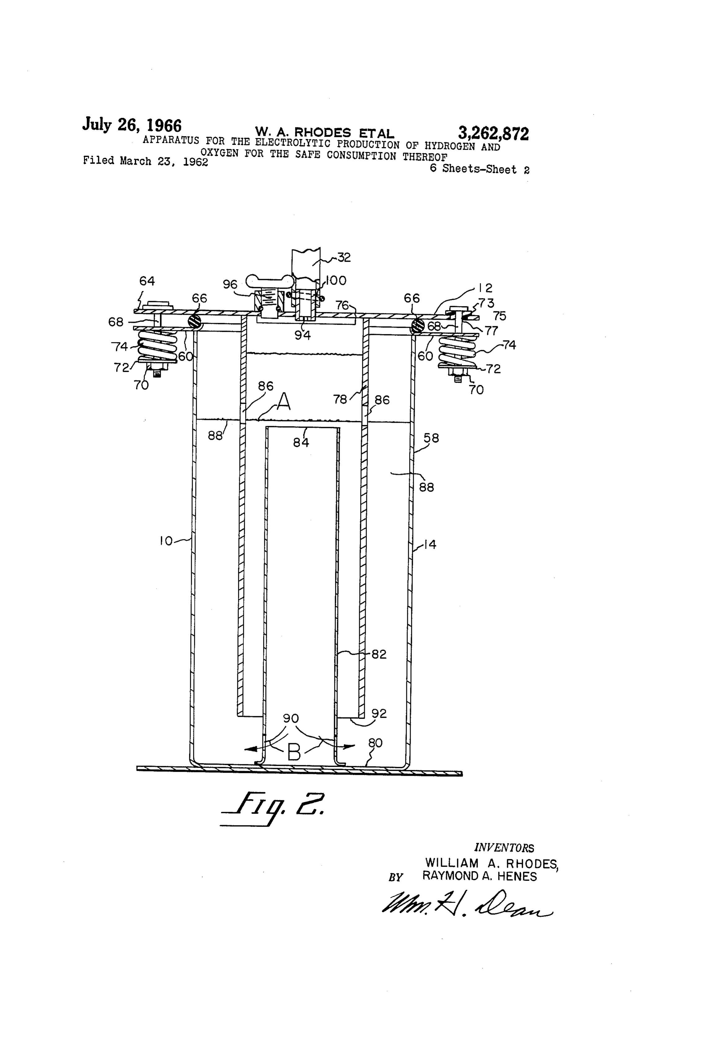
Another object of the invention is to provide a novel gen and oxygen producing generator together with a con generator for electrolytically producing hydrogen and 50 duit means for delivering the hydrogen and oxygen to a torch and including flash-back arrestors and a power Sup oxygen in Water. ply to the generator as well as a blower for cooling the Another object of the invention is to provide a torch rectifier and diluting bleed-off gas from the generator; and safe means, coupled thereto, for electrolytically pro FIG. 2 is an axial sectional view of the electrolytic ducing hydrogen and oxygen and for safely delivering a 55 hydrogen and oxygen generator;
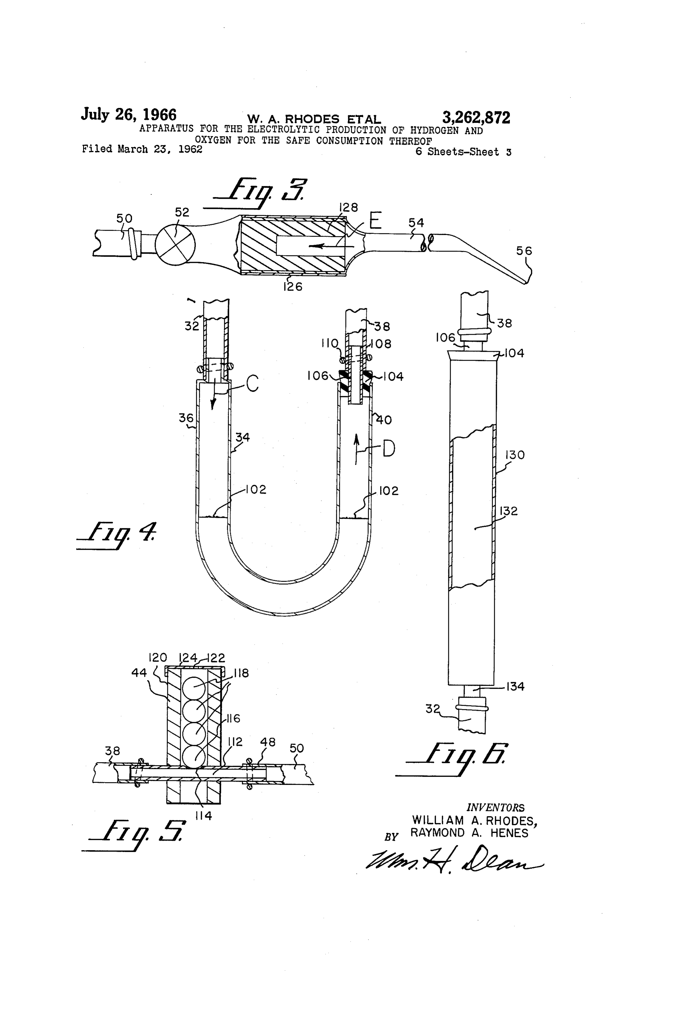
mixture of these gases to said torch. FIG. 3 is an enlarged side elevational view of the torch, Another object of the invention is to provide a very simple and economical torch means having a safe Source of the present invention, showing portions thereof, broken away and in section to amplify the illustration;
of electrolytically produced hydrogen and oxygen. FIG. 4 is an enlarged fragmentary sectional view of a Another object of the invention is to provide a genera 60 flash-back arrestor of the present invention; tor wherein hydrogen and oxygen are electrolytically pro duced in the presence of a highly concentrated alkali in the bleed-offis pressure
FIG. 5 an enlarged fragmentary sectional view of regulator of the invention;
water, whereby the size of the generator may be reduced FIG. 6 is an enlarged fragmentary side elevational view in size versus gas delivery volume ratio not attained here of a modified form of the flash-back arrestor of the inven tofore.
Another object of the invention is to provide a genera 65 tion showing portions broken away and in Section to amplify the illustration;
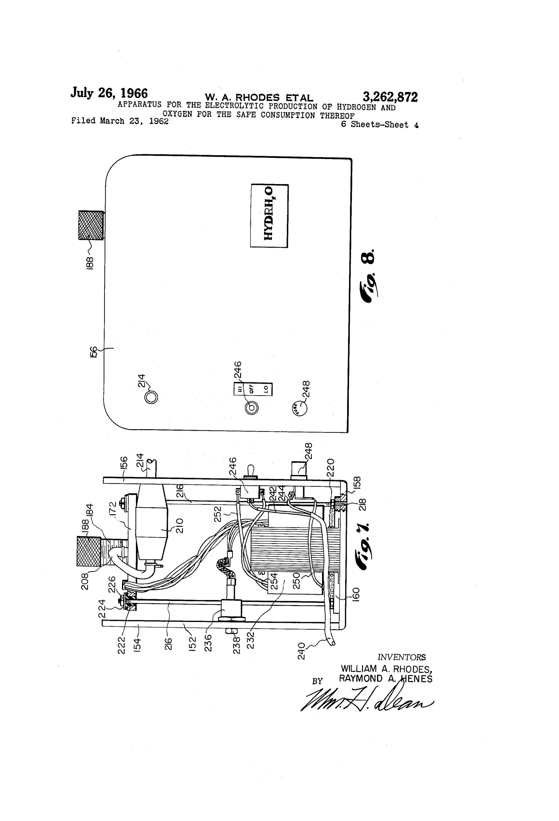
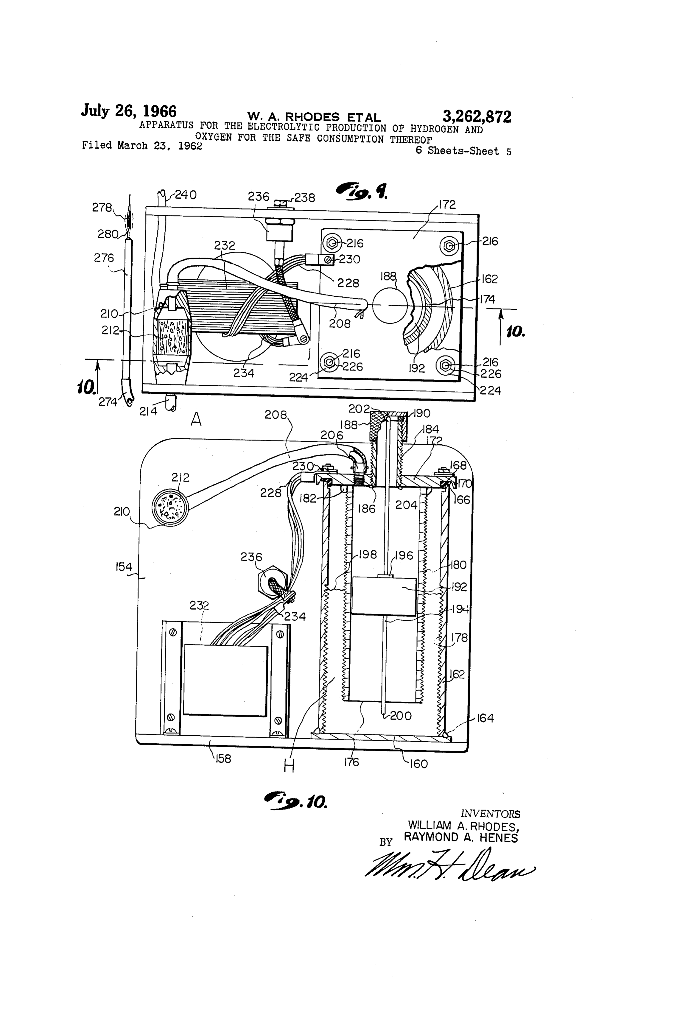
tor for electrolytically producing hydrogen and OXygen; FIG. 7 is an end view of a modified form of generator said generator comprising novel, resilient pressure relief for the electrolytic production of hydrogen and oxygen; mechanism to prevent damage to the generator in the FIG. 8 is a side elevational view thereof; event combustion of hydrogen and oxygen takes place FIG. 9 is a top or plan view of the modified generator therein. for the electrolytic production of hydrogen and OXygen, Another object of the invention is to provide a novel as shown in FIGS. 7 and 8 of the drawings;
Page 8
s 4.
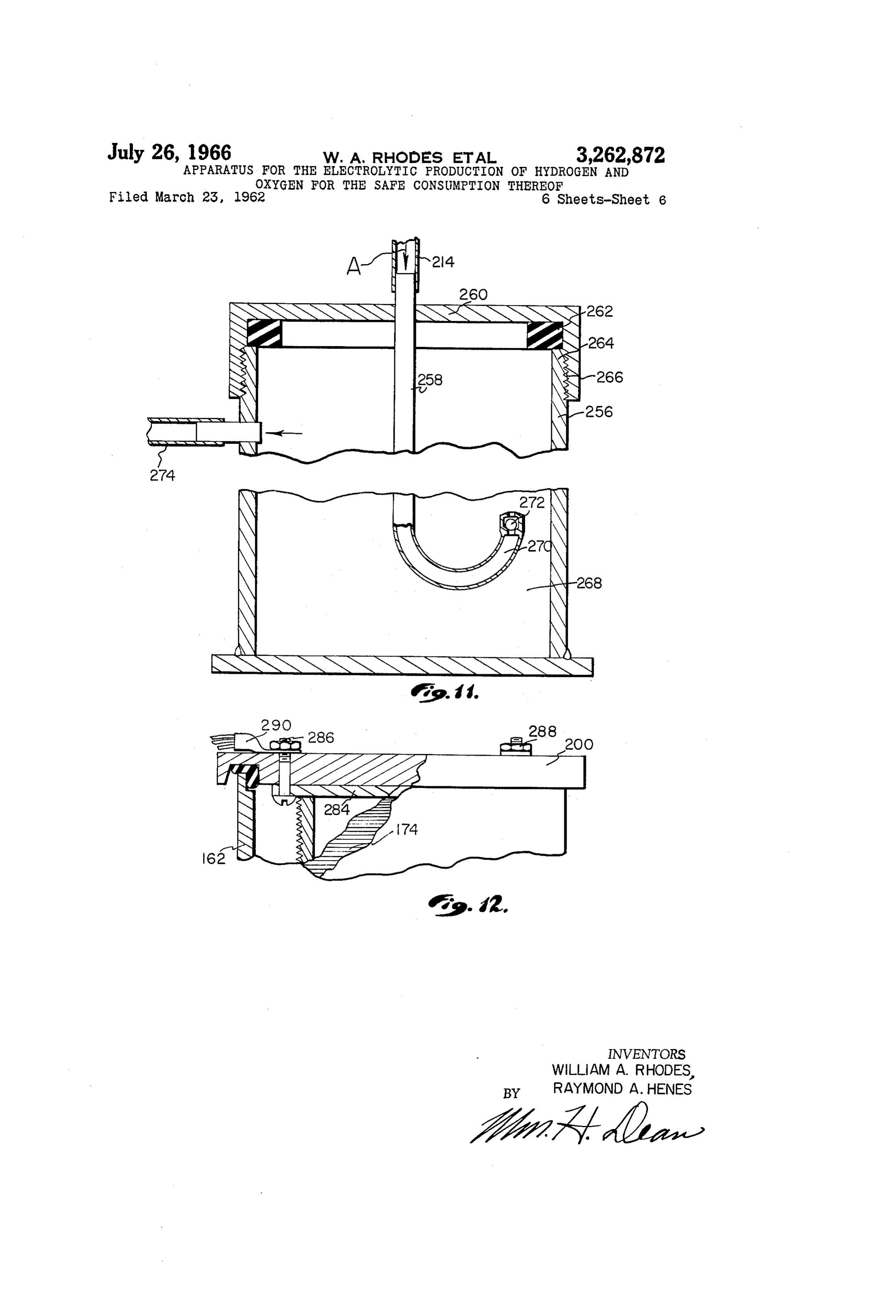
FIG. 10 is a sectional view taken from the line 10-10 space 88 between the outer wall of the cylindrical portion of FIG. 9; 53 and the cylindrical portion 78. FIG. 11 is a sectional view of a hydrocarbon fluid en The cylindrical portion 82 of the cathode is provided trainment tank of the present invention; and with openings 90 in its lower portion to permit circulation FIG. 12 is a fragmentary sectional view of a further 5 of the solution in the direction of arrows B, shown in modification of the invention. FiG. 2 of the drawings.
As shown in FIG. 1 of the drawings, an electrolytic During hydrogen and oxygen production, bubbles of hydrogen and oxygen generator 10 is provided with an both gases rise upwardly in the solution and foaming anode 12 and cathode 14, electrically coupled to electrical of the solution takes place at the upper surface thereof. conductors 16 and 28, respectively, which is supplied 10 This foaming action causes the solution to foam over into energy by means of a rectifier 20 receiving energy through the upper open end 84 of the cylindrical portion 82, which conductors 22 and 24 from a transformer 26 coupled to a causes a constant downflow of the solution therein. The conventional alternating current line 28. openings 90 permit this downward flow and escape of the Hydrogen and oxygen produced by the generator 10 Solution outwardly of the cylindrical portion 82 near the passes from an outlet 30 in the top of the generator 10 lower interior of the tank portion 58 of the cathode. and into a tube 32 which is coupled to one upstanding leg These openings 90 are below a lower open end 92 of the 34 of a U-tube flash-back arrestor 36. Another tubular cylindrical portion 78 of the anode so that the solution may circulate freely from the interior of the cylindrical conduit is coupled to the opposite upstanding leg 40 of the
U-tube flash-back arrestor 36 and this tube 38 conducts portion 82 outwardly through the openings 90 and back the mixture of hydrogen and oxygen to an inlet 42 of a 20 into the tank portion 58 of the cathode. bleed-off pressure regulator 44. The openings 86 in the cylindrical portion 78 of the The bleed-off pressure regulator 44 is provided with a anode permit foam and bubbles to pass from a space 88 bleed-off outlet 46 disposed to deliver excess hydrogen hereinbefore described, into the interior of the cylindrical and oxygen to the atmosphere and will be hereinafter portion 78 of the anode.
described. The bleed-off pressure regulator 44 is pro 25 In the central cover portion 76 of the anode, an outlet vided with an outlet 48 to which a flexible conduit 50 is orifice 94 is provided to control flash-back into the gen connected. The opposite end of this conduit 50 is con erator i0, as will be hereinafter described in detail. This nected to a torch valve 52 disposed to deliver the mixture orifice 94 provides an outlet for a mixture of hydrogen of hydrogen and oxygen to a torch 54 having a top 56 at and oxygen produced in the generator 10. which combustion of hydrogen and oxygen takes place. 30 As shown in FIG. 2 of the drawings, the central cover Referring now to details of the electrolytic hydrogen portion 76 of the anode is provided with a screwthreaded and oxygen generator, as shown in FIG. 2, it will be seen filler plug 96, which may be removed to permit the addi that the anode 12 provides a cover for the generator. tion of water to the alkali solution in the generator 10. This cover is coupled to the cathode 14, which generally The tubular conduit 32 is coupled to a hollow cylin forms the tank structure of the generator. drical sleeve 100, welded or otherwise secured in the The cathode 14 comprises a long slender cylindrical central cover portion 76 of the anode to provide an out tank portion 58 composed of pure iron from which hy let for the mixture of hydrogen and oxygen produced in drogen bubbles are produced, as will be hereinafter de the generator. The orifice 94, as hereinbefore described, scribed. This cylindrical tank portion 58 is provided 40 is disposed in the lower end of the tube 100 and this orifice with an angular flange 60 which is slightly spaced from a may be approximately .050 of an inch in diameter as com similar flange 64 of the anode 12. Disposed between the pared to an orifice diameter of .040 of an inch at the tip flange 60 and 62 is a compressible O-ring 66 preferably 56 of the torch 54, as will be hereinafter described in made of resilient dielectric material such as rubber, or its detail.
equivalent. Bolts 68 extend through the flanges 60 and Direct current is supplied to the anode and cathode 62 and nuts 70, screwthreaded on the bolts 68, engage a 45 structures of the generator 10, in accordance with the washer 72, which bears against compression springs 74, concentration of the alkali, such as sodium hydroxide, or engaging the flange 60, whereby the flanges 60 and 64 are an equivalent ionizing agent, and water. The direct cur forced toward each other into firm feeling engagement rent is applied with low voltage and relatively high am with the O-ring 66. Insulator sleeves 73 fit in openings perage, as for example, 4 volts at 250 amperes is suitable 75 in the flange 64 and the bolts 68 extend through central 50 when using the foregoing, substantially saturated solution openings 77 in the insulating sleeves 73. of alkali and water. This provides for a current density The anode 12 is provided with a central cover portion of approximately 1 ampere to 1 square inch or less of the 76 having a nickel-plated iron cylindrical section 78, generator area.
welded or otherwise secured thereto, and extending down 55 It will be appreciated that the foregoing proportions of Wardly and concentrically into the tank-shaped portion 58 alkali and water represent a substantially saturated solu of the cathode 14. The cathode 14 is pure iron and is tion in which the alkali and water are substantially equal provided with a bottom portion 80 having a pure iron in Weight. This highly concentrated solution tends to upstanding cylindrical portion 82 welded or otherwise minimize electrical resistance with attendant temperature Secured thereto. This cylindrical portion 82 of the cath rise in the electrolyte and therefore permits the system to ode 14 is disposed concentrically of the cylindrical por 60 operate with low voltage and relatively high amperage. tion 78 of the anode, as hereinbefore described. Additionally, it will be understood that, due to low resist The tank portion 58 of the cathode 14 is partially filled ance of the electrolyte, the efficiency of the system is high with a solution of alkali and water. This solution is with a maximum production of hydrogen and oxygen gases highly concentrated, the alkali being in an amount equal 65 in proportion to the size of the generator. to that of the water, as for example, the weight of the The flash-back arrestor 34 is a U-shaped tube having up alkali Substantially equals the weight of the water. standing legs 36 and 40. This tube 34 contains non-in The Solution of water and alkali is disposed at a level is 40. ble liquid 102, which partially fills the legs 36 slightly above an upper end 84 of the cylindrical portion andThe leg 36 is coupled to the tube 32 and disposed to 82 of the cathode 14.
receive a mixture of hydrogen and oxygen gases in a direc
As shown in FIG. 2 of the drawings, the upper surface 70 tion of the solution is disposed as indicated by the line A and bubble of the arrow C, in FIG. 4 of the drawings. The gases the cylindrical portion 78 of the anode is provided with leg through the liquid 102 and move upwardly in the openings 86 which are partially above and below the ture of gases40 in a direction of the arrow D, in FIG. 4. The mix then passes upwardly through the tube 38 level A. These openings 86 permit foam to pass from a 75 toward the bleed-off pressure regulator 44.
Page 9
In the upper open end of the leg 40 of the U-tube 34 section 134 to which is connected an extension of the tube is a friction tight cork 104 having a solid, hollow tubular 32, shown in FIG. 1 of the drawings. member 106 therein. An end 108 of the outlet tube 38 is In operation, the modified flash-back arrestor 130, per clamped on the tubular member 106 by a resilient clamp mits a mixture of hydrogen and oxygen to bubble up ing ring 110. The cork 104, being secured in the upper Wardly through the water 132 and in the event of a flash end of the leg 40 by friction, may readily be blown out of back through the tube 38, the cork 104 may be blown out the open end of the leg 40 when and if a flash-back ex plosion occurs in the leg 40 above the surface of the liquid passtheback of upper end of the tube 130 and the liquid 132 may through the tube 32 but cannot pass rapidly 102. through the orifice 94 at the outlet of the generator, as The tube 38 is coupled to the inlet 42 of the pressure regulator 44, as shown in FIG. 5 of the drawings. This 0. shown in FIG. 2. This is a small orifice and might per mit only a very small portion of the water 132 to pass bleed-off regulator 44 is provided with a gas passage 112 therethrough before force of the flash-back explosion in having a vent opening 114 in its upper wall portion. the upper end of the tube 130 is relieved by expulsion of Seated in the vent opening 114 is a ball 116 preferably the cork 105.
made of nylon, other plastic, or stainless steel. As shown in FIG. 1 of the drawings, a blower 136 de Supported on and above the ball 116 are relatively livers air in a direction as indicated by arrows F so that heavy steel balls 118 which tend firmly to hold the ball 16 this air travels over the rectifier 20 for cooling the same intimately seated to close the vent opening 114. All of and also passes the bleed-off pressure regulator 44 in order the balls 116 and 18 are supported in a guide tube 120, to dilute the excess mixture of hydrogen and oxygen which which is disposed vertically to support the balls directly 20 bleeds off through the orifice 122, shown in FIG. 5 of the above the vent seat 114. drawings. The volume of air delivered by the blower It will be understood that the balls 118 may be made of 136 is sufficient completely to dilute the mixture of oxy various materials, as desired. However, these balls gen and hydrogen passing from the orifice 122 in order to should be made of heavy material in order to provide suf render it non-combustible, thus, the mixture of these gases ficient pressure to attain a desired bleed-off pressure of leaving the bleed-off pressure regulator 44 cannot be ig gases through the vent opening 14. It will be understood nited and thus such hazard is eliminated. that the bleed-off pressure through the vent opening 114 The blower 136 is provided with a motor 38 electri may be increased by adding heavy balls to the column cally coupled by conductors 140 and 142 to conductors 144 above the balls 116. Conversely, the bleed-off pressure and 146 of the alternating current supply 28. A switch through the vent opening 114 may be reduced by reduc 30 148 is disposed to break the alternating current supply 28 ing the number of heavy steel balls. and is disposed in the line 144, thus the blower 136 and Various materials may be used in these pressure regulat transformer 26 are concurrently energized when the switch ing balls, as desired, depending upon the requirements. 48 is closed.
When gas pressure reaches a predetermined value in a Coupled to the line 144 around the switch 148 is a conduit 112, the column of pressure regulating balls is lamp 150 of low wattage capacity which always per raised slightly and the gas escapes upwardly therearound mits a small amount of energy to be conducted to the and through a vent opening 112 in a cap 124 at the upper transformer end of the casing 120. The gas passing through the vent generator 10 26always and rectifier 20 so that the electrolytic produces a very small amount of opening 152 will be diluted by a flow of atmosphere from hydrogen and oxygen. This may amount to only a a blower 136, as will be hereinafter described. 40 bubble now and then, whereby the gases in the gener A pressure regulated mixture of hydrogen and oxygen ator are not permitted to recombine completely and passes from an outlet 14 of the bleed-off pressure regu evacuate the generator when the switch 148 is open. lator 44 through the flexible conduit 50 to a control valve Only enough hydrogen and oxygen is thus generated to 52 which regulates the flow of gases to the torch 54. prevent evacuation of the generator 10. This torch 54 is provided with a handle portion 126 45 If the generator i0 is completely de-energized, the wherein a ceramic-type flash-back arrestor 128 is disposed. hydrogen and oxygen gases therein eventually recom As shown in FIG. 3 of the drawings, the handle portion bine and cause evacuation of the generator. If this is 126 of the torch 54 is hollow and the ceramic flash-back permitted, the modified flash-back arrester, shown in arrestor 128 is intimately disposed in the hollow handle FIG. 6, is also evacuated whereby the water 02 there portion 26 in order completely to block combustion 50 in is slowly drawn into the generator through the ori which may travel backwardly from the tip 56 of the torch fice 94. Subsequently, when the torch 56 is ignited, 54 in a direction of the arrow E, in FIG. 3 of the draw and in the event of undetected damage to the flash-back
The flash-back arrestor 128, for example, may be made arrestor 128, then the flash-back arrestor might fail and permit flame to travel all the way back to the generator of a porous Carborundum material, such as that used in 0.
grinding wheels. An 80-grit Carborundum has been found The U-tube flash-back arrestor 34 is not adversely very effective in arresting flash back through the torch 54, affected by evacuation of hydrogen and oxygen in the to the tube 50. generator, since the loop at the lower end of the U-tube It has been found that the torch 54 may be provided Structure always may retain water.
with tips 56 varying in orifice diameter from around .005 60 The lamp 150 thus serves the purpose of maintaining of an inch to .040 of an inch or greater and that under op a small amount of energy to be conducted by the gen erating conditions employing orifice sizes in this range, erator 10 to produce a nominal amount of hydrogen the flash-back arrestor 128 effectively prevents flame trav and oxygen, sufficient only to prevent total recombin el from the torch 54 to the tube 50. ing of the bases in the generator and thereby to pre As shown in FIG. 6 of the drawings, a modified flash vent evacuation of the flash-back arrestor 34. back arrestor communicates with the tube 38 and is gen Referring to FIG. 2 of the drawings, it will be seen erally located in a position similar to that of the flash that the generator 10 may relieve explosive pressure in back arrestor 34. This flash-back arrestor, as shown in ternally thereof, due to operation of the spring-loaded FIG. 6 of the drawings, is provided with a vertical tube cover 76, forming a part of the anode 2. 130 having a friction-connected cork 104 in the upper end 70 Should an explosion take place in the generator 10, thereof which is similar to the cork 104, hereinbefore described, in connection with the upper end of the leg the cover 76 may be raised by internal pressure, per mitting a relief of gas outwardly around the O-ring 66.
40 of the flash-back arrestor 34. This relief is permitted by resilience of the springs 74, The tube 130 is partially filled with water 132 and the which may be compressed and thereby permit the cover lower end of the tube 130 is provided with a reduced tube 76 to move upwardly relative to the O-ring 66 and
Page 10
thereby vent pressure from the interior of the generator is substantially level with the upper end of the filler O. neck 184. This charges the generator with a proper As shown in FIG. 7 of the drawings, the modification amount of water so that the electrolyte is at a proper of the invention comprises a frame and heat sink struc concentration and capable of electrolyzing water into ture 152 which is generally U-shaped. This frame struc hydrogen and oxygen gases.
ture is provided with a pair of substantially vertical The cathode casing 162 at its internal screwthreads side plates 152 and 155 integral with which is a base 168, generates oxygen which passes upwardly, as in plate 158. The frame and heat sink structure 152 is dicated by arrows in FIG. 10 of the drawings; said oxy preferably made of aluminum or other material hav gen being produced on the extended surface area of the ing a high heat transfer rate. Thus, the frame serves O threads 178 while comparable action of the anode on as an efficient heat sink structure to dissipate heat from its externally screwthreaded portion 186, produces hydro the generator, transformer and rectifier devices, as will gen and these gases mix above the electrolyte 198 and be hereinafter described in detail. pass upwardly through an opening 204 in the side wall Disposed between the side plates 154 and 156 is a of the reactor anode adjacent the cover plate 72. Thus, generator base plate 160 to which is welded an upstand 5 the gases pass inwardly to the interior of the anode ing hollow cylindrical generator casing 162 which serves 174 and pass outwardly through a tube fitting 206 screw as a reactor cathode for electrolytic production of oxy threaded in the cover 172. A tube 208 is coupled to the gen, as will be hereinafter described. This casing 162 is fitting 206 and extends to a flash-back arrestor casing 20 preferably made of steel pipe or tubing and is periph having a porous stone 212 therein through which the erally welded at 164 to the base plate 160. 20 mixture of hydrogen and oxygen passes to a tubular con The upper annular edge 166 of the casing 62 is en duit 214, as will be hereinafter described in detail. gaged with a sealing gasket 168 held in a groove 170 of The electrolyte 198 in the generator is preferably as a cover 172 to the lower side of which is welded a hollow disclosed in a patent application of William A. Rhodes tubular reactor anode 174. This anode 174 is prefer for Electrolyte Solution, Serial Number 109,521, filed ably made of steel pipe or tubing and is suspended con 25 May 12, 1961.
centrically in the outer casing 162 and provided with a As shown in FIG. 7 of the drawings, the structure of lower end 176 spaced from the upper Surface of the the generator and the frame and heat sink i52, are held base plate 160, all as shown best in FIG. 10 of the draw in assembly by four bolts 216. These bolts 216 are pro ings. The casing 62 is provided with an internally vided with lower screwthreaded ends 218 which are threaded wall 178; conventional screwthreading of this 30 screwthreaded in the base plate 158 and disposed on wall 178 provided extended surface area thereof for a the screwthreaded portions of the bolts 216 are jam nuts large volume production of oxygen in proportion to 220 which are tightened downwardly upon the upper the overall external dimensions of the casing 162. portion of the base plate 160 of the generator casing 162 It will be understood that the extended surface area to hold said plate intimately engaged with the base plate of the internal wall of the casing 162 may be provided by 158 of the frame and heat sink structure. other means than the screwthreads 178, as for exam Surrounding the normally upper ends of the bolts 216 ple, inwardly directed fins, or the like. The annular conare electrical insulation bushings 222 which insulate struction of the casing 162 is very readily provided withthese bolts from the cover 172 and engaging the insula an internal screwthread 178 which is the simplest man tion bushings are steel bushings 224 engaged by screw ner of extending the internal cathode Surface area of 40 threaded nuts 226 which firmly clamp the cover 172 the generator. downwardly to hold the gasket 168 intimately in sealing The reactor anode 174 is provided with external an engagement with the upper peripheral edge 66 of the nular screwthreads 80 to extend the surface area of generator casing 162.
the anode for the production of a maximum amount of The cover 172 by means of the insulation bushings 222 hydrogen in proportion to the size of the generator. and the gasket 168 is completely electrically insulated It will be obvious to those skilled in the art that from the generator casing cathode structure and, as here since this reactor anode 74 is annular, that external inbefore described, the anode 174 is electrically coupled annular fins may be provided in lieu of the screwthreads to the cover 172 by the welding 182. 180. An electrical conductor 228 is coupled by means of a The upper end of the tubular anode structure 174 is 50 Screw 230 to the cover 172 and this electrical conductor welded at 82 to the cover 172 and the gasket 168 acts 228 is also coupled to a transformer 232. to insulate the cover 172 from the cathode casing 162, Another conductor 234 coupled to the transformer is as will be hereinafter described. connected through a diode rectifier 236 with the side wall Concentrically of the cover 172 is a filler neck 184 154 of the frame and heat sink structure, all as shown of hollow cylindrical construction which is peripherally best in FIGS. 7 and 10 of the drawings. welded at 186 in a central opening in the cover 172. It will be seen that the diode rectifier is electrically A cap 188 is screwthreaded on the neck 184 and is connected and thermally conductively coupled to the provided with a gasket 190 to provide for a sealing en plate 154 by means of a bolt 238 and that the base plate gagement of the cap 188 with the upper end of the filler 158 of the frame is electrically coupled to the casing 162
Disposed concentrically and internally of the hollow 60 Which
is the generator cathode.
conventional 110-volt alternating current line 240 is cylindrical anode 74 is a float 192 preferably made of provided with a pair of conductors 242 and 244 which Styrofoam, or the like.
This float 192 is mounted on a rod 194 having a are connected to a Switch 246 and a fuse 248, respectively. shoulder 196 thereon against which the float 192 moves A conductor 250 extends from the fuse 248 to one wind upwardly while buoyantly supported on the electrolyte 65 ing of the transformer 232 and a pair of conductors 242 198 in the generator. The rod 194 is provided with a and 244 extend to multiple windings of the transformer lower end 200 which may engage the base plate 160 232 to vary the output thereof in order to provide for when the electrolyte 198 is at a low level. The rod varying amounts of energy to be dissipated from the cath 194 is also provided with an upper end 202 which may 70 Ode and anode structures 162 and 174, respectively, be level with the upper end of the filler neck 84 when whereby a variation may be attained in the amount of the electrolyte 198 is at a proper level in the gener hydrogen and oxygen delivered through the tube 208 and ator. Thus, the addition of water through the filler neck flash-back arrestor 210 to the tube 214. 184 may be continued until the float 192 rises to carry The tube 24 delivers a mixture of hydrogen and the upper end 202 of the rod 194 to a position which oxygen into a fluid containing tank 256, as shown in FIG.
Page 11
11 of the drawings, and indicated by arrows A, in FIGS. tion, as shown in FIG. 12 of the drawings, the narrow 10 and 11 of the drawings. strap 284 permits replacement of the anode 174 by The mixture of hydrogen and oxygen passes down simple removal of the bolts 286 and 288. These bolts wardly into a tube 258 which is supported in a cover extend through the cover 200 and are sealed with suitable 260 and sealed realtive thereto. The cover 260 is provided cement so that no leakage of hydrogen and oxygen may with a gasket 262 engaged in sealed relation with an up take place around these bolts. per end 264 of the tank 256. A screwthreaded skirt 266 It will be appreciated that the anode and cathode struc of the cover 260 is screwthreaded on the upper end of tures, as shown in FIG. 10 of the drawings, is also prefer the tank 256 for holding the cap 260 in sealed relation ably provided with an extended surface area structure therewith. 10 comprising simple threads. This extended surface area Disposed in the tank 256 is a fluid such as methyl structure may take other physical form, as for example, alcohol, designated 268, or any equivalent fluid. the anode 174 may be a perforate tube or may have A tube 258 extends downwardly into this fluid and is various undulated surface structure providing an overall provided with a reverse bend having an upwardly ex area greater than the geometric unity of the physical sur tending portion 270 in which a ball check valve 272 is 15 faces. Thus, the terms "extended surface area' used disposed. A mixture of hydrogen and oxygen bubbles up herein may define any structure of the cathode and anode around the ball 272 and passes upwardly through the fluid elements of the invention which has surface area which is 268 and outwardly through a tube 274, as shown in either finned and ridged, undulating or perforate to pro FIGS. 10 and 11 of the drawings. vide an extended surface area greater than the geometric The mixture of hydrogen and oxygen then passes 20 unity of the structures from which the hydrogen and through a torch 26, shown in FIG. 9 of the drawings, to Oxygen may be emitted.
a combustion flame 278. This is obviously an advantage to provide for a very The methyl alcohol is entrained in the hydrogen and compact generator structure having optimum production oxygen and adds to the B.t.u. content of these two gases capabilities in accordance with its overall size. while at the same time tends to consume excess oxygen 25 It will be noted that the structure of the generator, as in the gases and secondary oxygen from the surrounding shown in FIG. 7 of the drawings, may be capable of with atmosphere so that any materials being welded by the standing a flash-back explosion therein without the danger flame 278 are thus surrounded by a reducing atmosphere of damaging the generator. It has been found that the which tends to combine with oxygen surrounding the explosion of hydrogen and oxygen in such a generator area of the weld thereby preventing oxidation of the ma 30 may be self-contained without creating unduly high pres terials being fused. SleS
The torch 278 is provided with a flame holding orifice It will be obvious to those skilled in the art that various which may be as small as .014 of an inch in diameter. A modifications of the present invention may be resorted small amount of aqueous condensate may tend partially to to in a manner limited only by a just interpretation of clog this fine orifice, however, the entrained methyl the following claims.
alcohol automatically clears any such aqueous condensate 1. In an electrolytic hydrogen and oxygen generator the from this orifice, thus keeping it clear and operative. combination of: a cylindrical tank having a bottom por During operation of the modified form of the invention, tion; a cover for said tank having a downwardly extend as shown in FIGS. 10 and 11 of the drawings, hydrogen 40 ing cylindrical electrode portion, said first mentioned and oxygen gases may be under slight pressure in the cylindrical portion of said tank having an outwardly ex tank 256 above the hydrocarbon fluid 268 therein. Due tending flange; an outwardly extending flange of said to a restriction of a flame holding orifice 280 of the covered portion overlying said last mentioned outwardly torch 276, residual pressure in the tank 256 above the extending flange; a gasket between said flanges; and spring electrolyte 268 may remain for a period of time after loaded means tending to force said flanges together in the generator is shut off. Accordingly, the check valve compressive contact with said gasket, said spring loaded 272 is disposed to prevent flow of hydrocarbon fluid 268 means yieldable to permit said flanges to separate from backwardly through the tube 258 in the event the cap 188 said gasket when pressure in said tank is excessive. of the filler neck 184 is removed before such residual 2. In an electrolytic hydrogen and oxygen generator pressure in the tank 256 has been relieved through the the combination of: the cylindrical tank having a bottom orifice 280 of the torch 276. Thus, the check valve 272 50 portion; a cover for said tank having a downwardly ex effectively prevents hydrocarbon fluid from flowing back tending cylindrical electrode portion, said first mentioned wardly into the generator and into the electrolyte 198 cylindrical portion of said tank having an outwardly ex therein. tending flange; an outwardly extending flange of said The check valve 272 is also effective to prevent back covered portion overlying said last mentioned outwardly flow of hydrocarbon fluid into the generator after the extending flange; a gasket between said flanges; and operation of the generator is discontinued. Under these Spring loaded means tending to force said flanges together conditions, the remaining mixture of hydrogen and oxy in compressive contact with said gasket, said spring loaded gen in the generator tends to recombine into water thus means yieldable to permit said flanges to separate from creating a partial vacuum in the generator which tends to said gasket when pressure in said tank is excessive, a re pull fluid from the tank 256 backwardly into the gen 60 movable filler plug in said cover and a restricted outlet erator. in Said cover for hydrogen and oxygen produced in said generator.
In the modification, as shown in FIG. 12 of the draw ings, the anode 174 is similar in construction to that 3. In an electrolytic hydrogen and oxygen generator shown in FIG. 10 of the drawings but is welded to a nar the combination of: a cylindrical tank member having an row strap 284 which is held to the cover 200 by bolts 65 enclosed bottom portion; an upstanding cylindrical mem 286 and 288. The bolt 286 extends through a fixture ber conductively coupled to said bottom; a cover for said 290 of the conductor 228, hereinbefore described. tank; a downwardly extending cylindrical member elec It will be understood that the casing 162 which forms trically coupled thereto and surrounding said upwardly the cathode of the generator, may be made of bare steel 70 extending cylindrical member; said tank adapted to con and that the anode 174, shown in FIGS. 10 and 12 of the tain an electrolytic solution, said downwardly extending drawings, may also be made of steel and since it pro cylindrical portion having openings therein near the upper duces oxygen, destruction of this anode gradually takes end of said upwardly extending cylindrical portion; an place and it is therefore to be considered as an expend outlet in said cover internally of said downwardly extend able item of the generator. Accordingly, in the modifica ing cylindrical portion for the delivery of the mixture of hydrogen and oxygen from the generator.
Page 12
4. In an electrolytic hydrogen and oxygen generator casing; an internal ridge and groove surface of said cylin the combination of: a cylindrical tank member having an drical electrode directed toward and in spaced relation to enclosed bottom portion; an upstanding cylindrical mem said ridge and groove internal surface of said casing; a ber conductively coupled to said bottom; a cover for normally lower end of said cylindrical electrode spaced said tank; a downwardly extending cylindrical member from the bottom of said casing; said casing adapted to electrically coupled thereto and surrounding said upwardly contain aqueous electrolyte in contact with both said extending cylindrical member; said tank adapted to con ridge and groove surfaces; and a source of electrical tain an electrolytic solution, said downwardly extending energy having conductors coupled to said cover and said cylindrical portion having openings therein near the upper casing to effect operation of said casing as a cathode end of said upwardly extending cylindrical portion; and IO and said cylindrical electrode as an anode; and an an outlet in said cover internally of said downwardiy ex outlet for said generator to conduct a mixture of tending cylindrical portion for the delivery of the mixture hydrogen and oxygen gases therefrom; a tubular filler of hydrogen and oxygen from the generator, said upstand neck on said cover communicating with the interior of ing cylindrical member having openings therethrough said hollow cylindrical electrode; a removable seal cap near said enclosed bottom portion. 5 on said filler neck; a float on said electrolyte internally 5. In a generator for electrolytic production of hydro of said hollow cylindrical electrode; and an electrolyte gen and oxygen the combination of: a closed bottom level indicating rod carried by said float and projecting cylindrical casing of electrical conducting material having upwardly in said filler neck.
an upper open end; a cover of electrical conductor ma 8. In a generator for electrolytic production of hy terials for said casing; gasket means forming a seal and 20 drogen and oxygen the combination of: a closed bottom electrical insulator between said upper open end of said cylindrical casing of electrical conducting material having casing and said cover; a hollow cylindrical electrode con an upper open end an a ridge and groove internal sur ductively coupled to said cover and suspended therefrom face; a cover of electrical conductor materials for said in said casing; an internal surface of said cylindrical casing; gasket means forming a seal and electrical insu electrode directed toward and in spaced relation to said lator between said upper open end of said casing and internal surface of said casing; a normally lower end of said cover; a hollow cylindrical electrode conductively said cylindrical electrode spaced from the bottom of said coupled to said cover and suspended therefrom in said casing; said casing adapted to contain an ionizing solu casing; an internal ridge and groove surface of said tion in contact with both said surfaces; and a source of cylindrical electrode directed toward and in spaced rela electrical energy having conductors coupled to said cover 30 tion to said ridge and groove internal surface of said and said casing to effect operation of said casing as a casing; a normally lower end of said cylindrical elec cathode and said cylindrical electrode as an anode; and trode spaced from the bottom of said casing; said casing an outlet for said generator to conduct a mixture of hy adapted to contain in contact with both said ridge and drogen and oxygen gases therefrom; said source of elec groove surfaces; and a source of electrical energy having trical energy including a transformer and rectifier means; 35 conductors coupled to said cover and said casing to effect a combined frame and heat sink means thermally con operation of said casing as a cathode and said cylindrical ductively coupled to said casing and said rectifier means electrode as an anode; and an outlet for said generator for supporting said casing and rectifier means and for to conduct a mixture of hydrogen and oxygen gases there collecting heat therefrom. from; said source of electrical energy including a trans 6. In a generator for electrolytic production of hy 40 former and rectifier means; a frame and heat sink means drogen and oxygen the combination of: a closed bottom thermally conductively coupled to said casing and said cylindrical casing of electrical conducting material having rectifier means; and rods connected to said frame and ex an upper open end; a cover of electrical conductor ma tending upwardly through said cover to hold said cover terials for said casing; gasket means forming a seal and and said casing together and in assembly with said frame; electrical insulator between said upper open end of said and electrical insulator bushings in said cover around said casing and said cover; a hollow cylindrical electrode con rods to insulate said cover from said frame and said ductively coupled to said cover and suspended therefrom casing.
in said casing; an internal surface of said cylindrical elec 9. In a generator for electrolytic production of hy trode directed toward and in spaced relation to said in drogen and oxygen the combination of: a closed bottom ternal surface of said casing; a normally lower end of cylindrical casing of electrical conductor material having said cylindrical electrode spaced from the bottom of said an upper open end and a ridge and groove internal sur casing; said casing adapted to contain an ionizing solution face; a sealed cover for said upper open end of said cas in contact with both said surfaces; and a source of elec ing; a hollow cylindrical electrode suspended from said trical energy having conductors coupled to said cover cover in said casing; an external ridge and groove surface and said casing to effect operation of said casing as a of said cylindrical electrode directed toward and in spaced cathode and said cylindrical electrode as an anode; and relation to said ridge and groove internal surface of said an outlet for said generator to conduct a mixture of hy casing; a normally lower end of said cylindrical electrode drogen and oxygen gases therefrom; said source of elec spaced from the bottom of said casing; said casing trical energy including a transformer and rectifier means; adapted to contain aqueous electrolyte in contact with both a combined frame and heat sink means thermally con 60 said ridge and groove surfaces; and a source of electrical ductively coupled to said casing and said rectifier means energy having conductors coupled to said hollow cylin for supporting said casing and rectifier means and for drical electrode and said casing to effect operation of said collecting heat therefrom; one electrical conductor of said casing as a cathode and said cylindrical electrode as an source of electrical energy coupled to said frame; said anode; and an outlet for said generator to conduct a casing electrically coupled to said frame; and another mixture of hydrogen and oxygen therefrom; a tubular electrical conductor of said source coupled to said cover. filler neck on said cover communicating with the interior 7. In a generator for electrolytic production of hy of said hollow cylindrical electrode; a removable seal cap drogen and oxygen the combination of: a closed bottom on said filler neck; a float on said electrolyte internally cylindrical casing of electrical conducting material having of said hollow cylindrical electrode; and an electrolyte an upper open end and a ridge and groove internal sur 70 level indicating rod carried by said float and projecting face; a cover of electrical conductor materials for said upwardly in said filler neck.
casing; gasket means forming a seal and electrical insu 10. In a generator for electrolytic production of hy lator between said upper open end of said casing and drogen and oxygen the combination of: a partially closed said cover; a hollow cylindrical electrode conductively cylindrical casing of electrical conductor material having coupled to said cover and suspended therefrom in said 75 an open end and an extended surface area electrode
Page 13
means; a sealed cover for said open end of said casing; References Cited by the Examiner a hollow cylindrical electrode supported by said cover in UNITED STATES PATENTS said casing; extended surface area means of said cylin drical electrode in spaced relation to said extended Sur 308,276 11A1884 Paine ----------- 204-129 X face area means of said casing; an end of said cylindrical 370,067 9/1887 Knapp ------------ 158-27.4 electrode spaced from an adjacent portion of said casing; 1,154,091 9/1915 Burdett ------------ 204-266 said casing adapted to contain aqueous electrolyte in 1,872,290 8/1932 Hitner -------------- 204-26 contact with both said extended surface area means; and 1,905,627 4/1933 Holand. a source of electrical energy having conductors coupled 2,315,758 4/1943 Willits ---------- 137-533.11 to said hollow cylindrical electrode and said casing to O 2,373,032 4/1945 Klein -------------- 204-278 effect operation of said casing as one electrode and said 2,418,200 4/1947 Smith ------------- 158-27.4 cylindrical electrode as the other electrode; and an outlet 2,728,121 12/1955 Goument ----------- 204-278 for said generator to conduct a mixture of hydrogen and 2,899,974 8/1959 Gratzmuller -----. 37-533.1 oxygen from said electrodes and said casing; a filler neck 3,117,066 1/1964 Juda --------------- 204-260 on said cover communicating with the interior of said 5
FOREIGN PATENTS
casing; a float internally of said hollow cylindrical elec 189,214 9/1907 Germany. trode and disposed on said electrolyte; and a rod coupled to said float and extending upwardly in said filler neck; JOHN H. MACK, Primary Examiner. and a cap enclosing and sealing the upper open end of said filler neck. 20 T. TUFARIELLO, Assistant Examiner.
Provenance
- Collection
- Cited prior art
- Original PDF
- patentimages.storage.googleapis.com →
- Filed
- 1962-03-23
- Pages
- 13
- Method
- pdftotext (the PDF's own text layer) + pdftoppm 300dpi page scans
- Source
- Google Patents bibliographic record
- Granted
- 1966-07-26
- Inventors
- William A Rhodes; Raymond A Henes; Henes Manufacturing Co
- Transcribed from
- patentimages.storage.googleapis.com →