patent · US4511440
Process for the electrolytic production of fluorine and novel cell therefor
16 April 1985
Page 1 — bibliographic record
United States Patent (19) 11) Patent Number: 4,511,440 Saprokhin et al. (45) Date of Patent: Apr. 16, 1985 54 PROCESS FOR THE ELECTROLYTEC 200584 12/1982 Japan ................................... 204/294 PRODUCTION OF FILUORINE AND NOVEL 668465 3/1952 United Kingdom ................ 204/247 CELL THEREFOR 852369 10/1960 United Kingdom . (75) Inventors: Alexander M. Saprokhin, Amherst; Primary Examiner-Donald R. Valentine David J. Friedland, Snyder; Richard Attorney, Agent, or Firm-Arthur J. Plantamura; Jay P. M. Baran, Cheektowaga; Jung T. Friedenson; Richard C. Stewart, II
Kim, Williamsville; Lynn E. 57 ABSTRACT
McCurry, Hamburg, all of N.Y. A cell and process is provided for the production of 73) Assignee: Allied Corporation, Morris fluorine comprising electrolyzing a liquid mixture of Township, Morris County, N.J. fluorides of alkali metal, ammonium and hydrogen fluo (21) Appl. No.: 564,639 ride. The cell anode comprises a stock of anode plates with internal passages or it may comprise a carbon 22 Filed: Dec. 27, 1983 shape provided with grooves and passages and fitted to a central conductor which conducts current from the 51 Int. Cl. .......................... C25B 1/02; C25B 1/24; exterior of the cell to the carbon anode plates within the C25B 11/03; C25B 11/12 cell. The anode having a substantially expanded work (52) U.S. C. ...................................... 204/60; 204/129;
204/241; 204/247; 204/266; 204/284; 204/294 ing surface has the capability of removing fluorine inter 58 Field of Search ................. 204/60, 266, 247, 284, nally. A louvered cathode permits most of the hydrogen 204/294, 128-129, 241 to be vented away from the zone between the elec trodes through which current passes thus reducing the 56) References Cited ohmic voltage loss. The cathode, rather than being
gauze. The anode, cathode and barrier may be cylindri 2,592,144 8/1952. Howell et al. ........................ 2O4/60 cal in form although other shapes, for instance rectan 2,684,940 7/1954 Rudge et al. ..... 204/60 X gular or square in cross section or even of hexagonal 2,693,445 1/1954. Howell et al. ........................ 2O4/60 2,996,446 8/1961 Davies et al. .... ... 204/6OX section, may be used if desired. Combination of the 3,773,644 A1973 Tricoli et al. .... ... 204/252 segmented anode design with a louvered cathode pro 4, 139,447 2/1979 Faron et al. ...... ... 204/239 vides a unique cell for fluorine production because vir 4,312,718 6/1980 Watanabe et al. .................... 2O4/60 tually the same electrolysis condition exists at any part of the anode and cathode.
FOREIGN PATENT DOCUMENTS
46-20808 6/1971 Japan ................................... 204/284 5 Claims, 16 Drawing Figures
S. NNN
Page 2
Drawing sheet — no readable text.
Page 3
Drawing sheet — no readable text.
Page 4
Drawing sheet — no readable text.
Page 5
Drawing sheet — no readable text.
Page 6
Drawing sheet — no readable text.
Page 7
Drawing sheet — no readable text.
Page 8
higher than those disclosed as "critical current densi
PROCESS FOR THE ELECTROLYTIC ties' in U.S. Pat. No. 4,312,718. PRODUCTION OF FLUORINE AND NOVEL CELL Current density is determined with reference to that THEREFOR portion of the anode surface which is directly opposite to the cathode.
DESCRIPTION A number of reasons exist for the inefficiency of prior The present invention relates to improvements in art electrolytic cells for fluorine production. One rea son, for example, is the low productivity which is due to electrolytic cells and processes for the electrolytic pro duction of fluorine which functions with relatively O low anodic current density and comparatively small greater economy and efficiency. anode length and/or an undesirably large distance be tween the anode and cathode. Also, because of low
BACKGROUND OF THE INVENTION anodic current density, these prior art cells necessitate The manufacture of fluorine by electrolysis of mix high equipment cost and high capital cost outlays. tures of fluorides is well known, the fluorine being de 15 It is thus apparent that a need exists for an improved rived, for example, from mixtures of an alkali metal cell configuration which enhances the economy as well fluoride and hydrogen fluorides. Systems of this kind as the efficiency of systems for the electrolytic produc are disclosed for example in U.S. Pat. Nos. 3,773,644 tion of fluorine.
known in such processes to use cells having anodes of SUMMARY OF THE INVENTION carbon or graphite, the cathode being of mild steel or 20 In accordance with the invention a novel cell for the other metal resistant to the action of the electrolyte. production of fluorine is provided. The production of Hydrogen is evolved at the cathode and fluorine, with fluorine by the electrolysis of a liquid mixture of hydro perhaps varying amounts of oxygen and other impuri gen fluoride and alkali and/or ammonium fluorides may ties, at the anode. Also as mixtures of hydrogen and be carried out at high current densities in a cell having fluorine give rise to violent explosions, such fluorine 25 a small anode-cathode gap and a greatly increased cells customarily have a diaphragm or partition, also anode and cathode length and functions without the referred to as a “skirt' designed to prevent mixing of evolution of fluorine as free bubbles at the vertical car the gases evolved at the two electrodes. In some cells bon surface of the anode assembly facing the cathode this diaphragm or partition extends downward in the and without formation of explosive mixtures of hydro interelectrode space for a distance equal to or even 30 gen and fluorine.
greater than that of the downward extension of the electrodes. In other fluorine cells, for example, and as to The the process for the production of fluorine according present invention comprises electrolyzing a liquid disclosed in British Pat. No. 852,369, a barrier, impervi mixture of at least ous to gases, extends downwards for a short distance and/or annoniumone of the fluorides of the alkali metal fluorides and hydrogen fluoride. At only into the interelectrode space. 35
It is recognized in prior art systems that the greater aploy temperature of the order of 80-110° C. one can en a fused substantially dry mixture of potassium the spacing between the electrodes, the greater must be fluoride and hydrogen fluoride having a composition the potential applied and the energy consumed to elec approximating substantially to KF, 1.8 HF to KF, 2.2 trolyze a given amount of material. Therefore it is desir HF. The invention uses a segmented anode in conjunc able to diminish the interelectrode space as far as is tion with a gas impermeable barrier which entirely commensurate with safety. Nevertheless, in general (except in certain cells with porous or gas permeable surrounds the upper part of the anode assembly. Alter carbon anodes) it has not been possible in the prior art to natively an anode comprising a carbon block with safely diminish the distance between anode and cathode grooves therein which in effect simulate a segmented (hereinafter termed the electrode separation) or the 45 anode may be employed. Such arrangements are used in distance between anode and gas barrier (hereinafter conjunction with a louvered cathode.
termed the anode gap) below certain limiting values. As The object of the present invention is to provide a stated in British Pat. No. 852,369, for instance, as the process of the aforesaid kind and apparatus therefor electrodes extend further downward into the electro which will permit a cell of the aforesaid kind to run at lyte below the bottom of the gas barrier, the interelec 50 significantly higher loads thus to obtain a larger output trode spacing must be increased. A minimum is pre of fluorine per unit of plant and furthermore maintain scribed for safe working such that when the electrodes the same or even lower cell voltage. extend to 8 inches below the gas barrier, the electrode The segmented anode assembly comprises a stack of separation should not be less than 2 inches (6.65 cm) carbon anode plates fitted to a central conductor which nor the anode gap less than 1 inch (2.54 cm). The corre 55 serves to conduct current from the exterior of the cell to sponding values when the electrodes are extended to 36 the carbon anode plates within the cell. Preferably the inches (91 cm) below the barrer are 4 inches (12 cm) carbon has a porosity of less than 25 percent. To pre and 1 1 1/16 inches (4.3 cm). However, if a special lou vent corrosion of the metal conductor of the upper part vered cathode is used, the figures for the electrode of the anode assembly and conductor between carbon separations appropriate to these depths of 8 inches (20.3 60 plates, magnesium tubes and rings are employed to cm) and 36 inches (91 cm) may be diminished to 2 protect these areas.
inches (5.7 cm) and 3 15/16 inches (10 cm), respec Due to the nonwetting surface of the carbon during tively. However, as noted in said British Patent, these normal electrolysis, the fluorine creeps up the vertical are prescribed as limiting minimum values if anodic electrode surface, travels around the shoulder of the 65 carbon plate and exits through the internal fluorine current density does not exceed 0.15 A/cm2.
By use of the anode of the invention, in which pas passage holes. Unlike chlorine which forms bubbles that sages for the flow of gases are provided, high current break off of carbon electrodes as they are formed, fluo densities are possible. Such current densities are even rine clings to the surface of, and moves up at the surface
Page 9
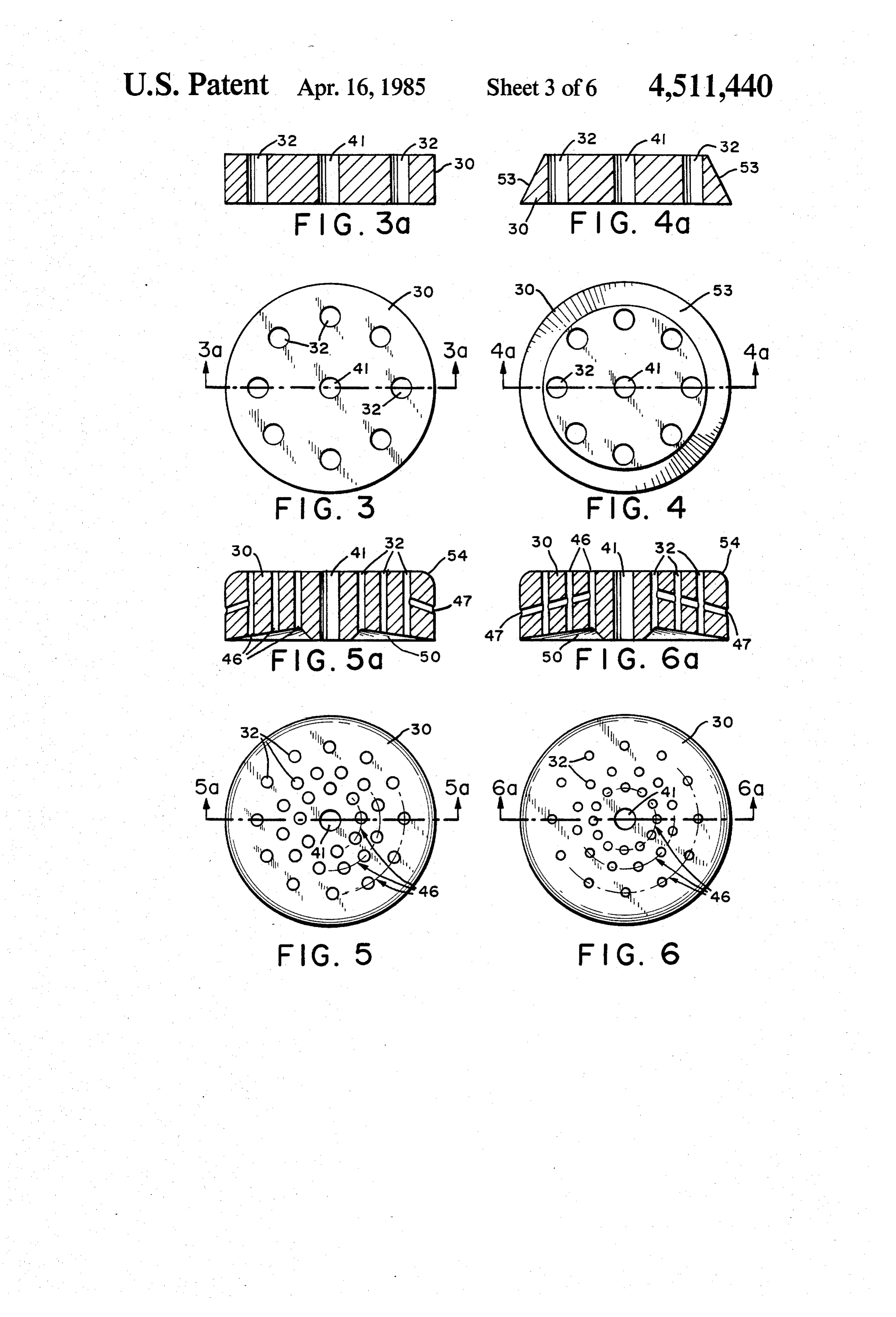
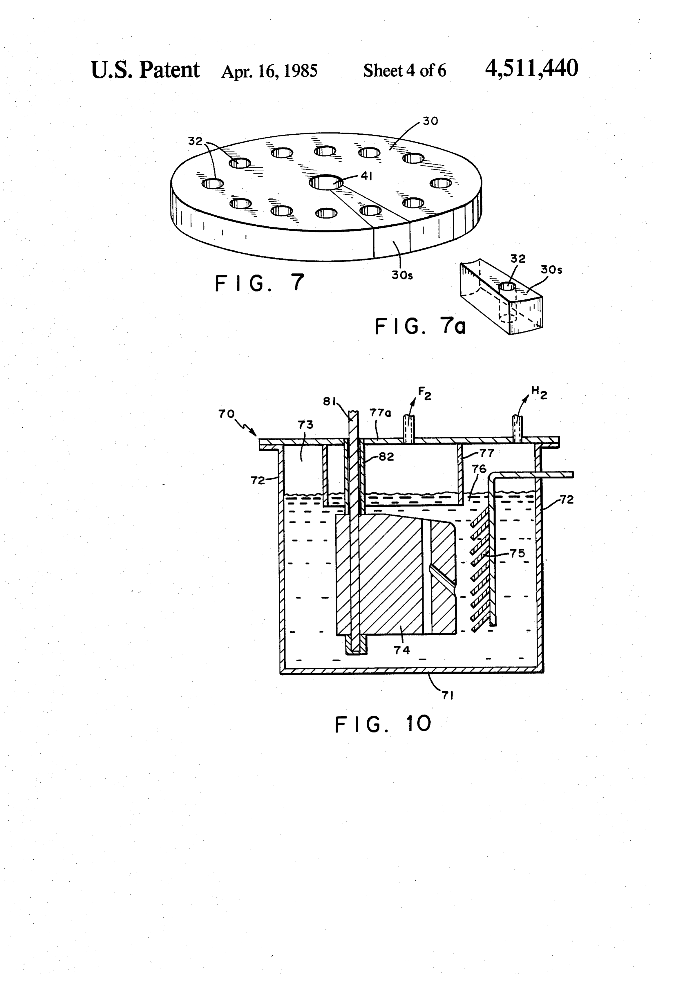
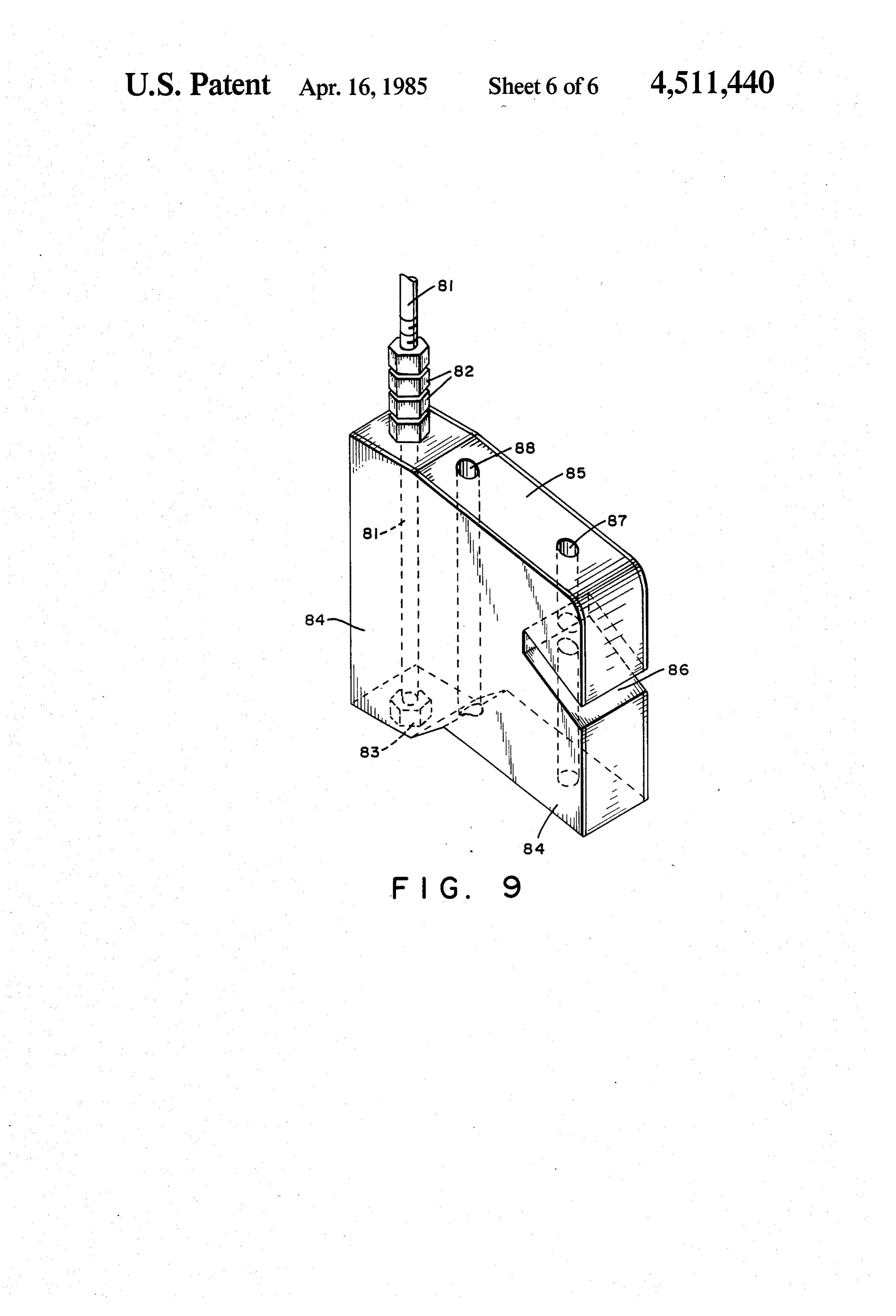
of, the electrode. This decreases the thickness of the FIG. 9 illustrates an alternate anode segment which fluorine layer on the carbon surface since fluorine will has been effectively converted into two blades by a exit internally and not over the electroactive surface transverse groove.
area. No large accumulation of fluorine on any plate FIG. 10 illustrates in cross-section the test cell using occurs since each anode plate will have its own exit for the anode segment of FIG. 9.
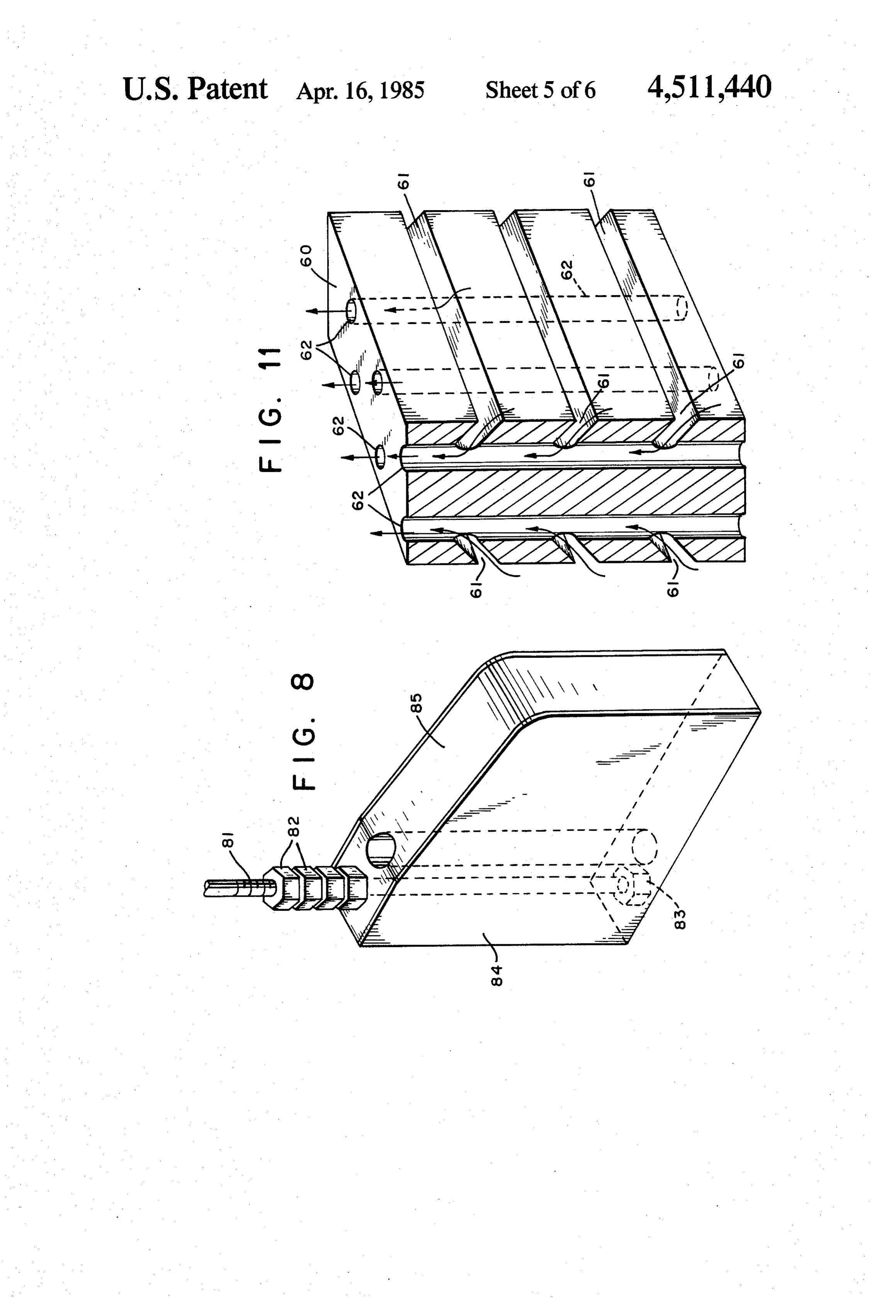
fluorine gas. Each anode plate will only be masked by FIG. 11 is an alternate anode showing the design of fluorine produced by that plate and not by fluorine from the invention applied to a rectangular anode geometry. other anode plates below it. As a result the voltage drop DESCRIPTION OF THE PREFERRED due to a fluorine layer on the anode will be lower than EMBODIMENTS for conventionally arranged vertical anodes. Because of 10 this novel design, the working surface of the anode According to the present invention a process for the assembly comprises not only the surface facing the production of fluorine comprises electrolyzing a liquid cathode but also the top and the bottom of each plate, mixture of at least one of the fluorides of the alkali metal inside the holes that form the internal fluorine passages 15 and/orA cell ammonium fluorides and/or hydrogen fluorine.
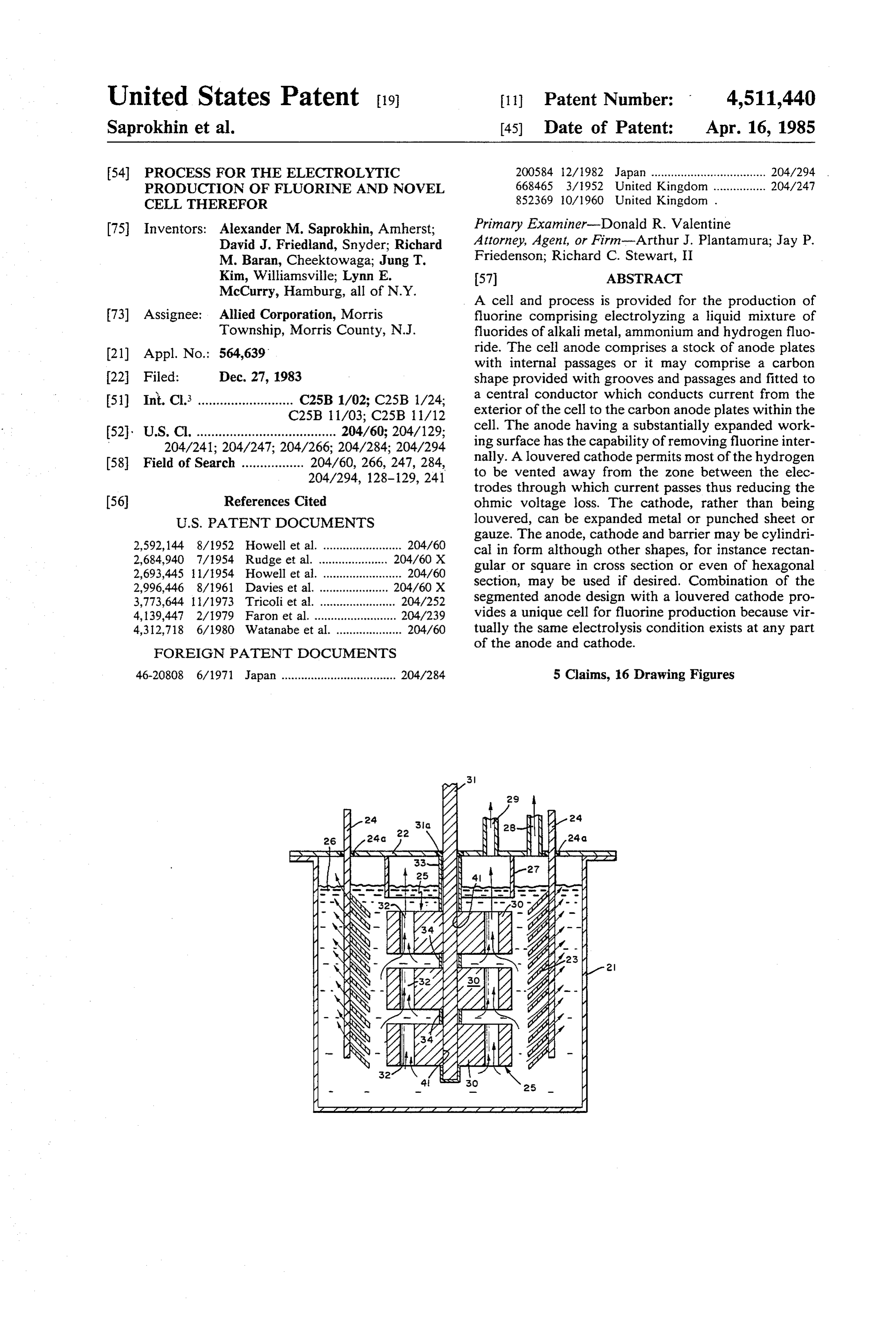
suitable for carrying out the invention is shown and inside the grooves between anodes.
The anode of stacked carbon plates is used in con in FIG. 1, not drawn to scale. Referring to the drawing, junction with a louvered cathode which permits most of 21 is a container of mild steel or other suitable resistant metal, provided with a lid 22, and 23 is a louvered cath the hydrogen to be vented away from the zone between ode which may be of mild steel, copper or other mate the electrodes. This significantly reduces the quantity of 20 rial substantially resistant to the electrolyte and prod hydrogen bubbles in the electrolyte through which ucts of electrolysis. The cathode is supported by an current passes between the electrodes reducing the electrolytically conducting cylinder-like member 24 ohmic voltage loss. Said cathode, rather than being which is insulated (at 24a) from the cell lid through louvered, can be expanded metal or one which consists which it passes. Surrounding the upper portion of the of punched sheet or gauze. If a plain sheet cathode is 25 anode assembly 25 and which dips into the electrolyte used, it will be necessary to increase anode-cathode 26 is a skirt or barrier 27. The pipes 28 and 29 serve for separation. Clearly if this separation is inadequate, then hydrogen and fluorine removal, respectively. when high current density is employed, there is a possi The anode assembly 25 in this design could be a stack bility of a particularly brisk evolution of hydrogen lead of circular carbon anode plates 30 fitted to a central ing to crowding of hydrogen bubbles within this space, 30 conductor 31 which serves to conduct current from the thus increasing the danger of hydrogen finding its way exterior of the cell to the carbon anode plates 30 within into the anode compartment. The anode, cathode and the cell. It is a solid metal rod or pipe, of copper or barrier may be cylindrical in form although any other other suitable metal insulated at 31a. To prevent corro suitable shape, for instance those having cross sections sion of the copper conductor 31 of the upper part of the that are rectangular, square, triangular, hexagonal, oc 35 anode assembly and copper conductor between plates, a tagonal, and the like, may be used if desired. magnesium tube 33 and magnesium rings 34 protect
BRIEF DESCRIPTION OF THE DRAWINGS
these areas. Magnesium passivates at an anodic poten tial. Other suitable resistant materials may be used for
FIG. 1 is a cross-sectional elevation view of the fluo this purpose.
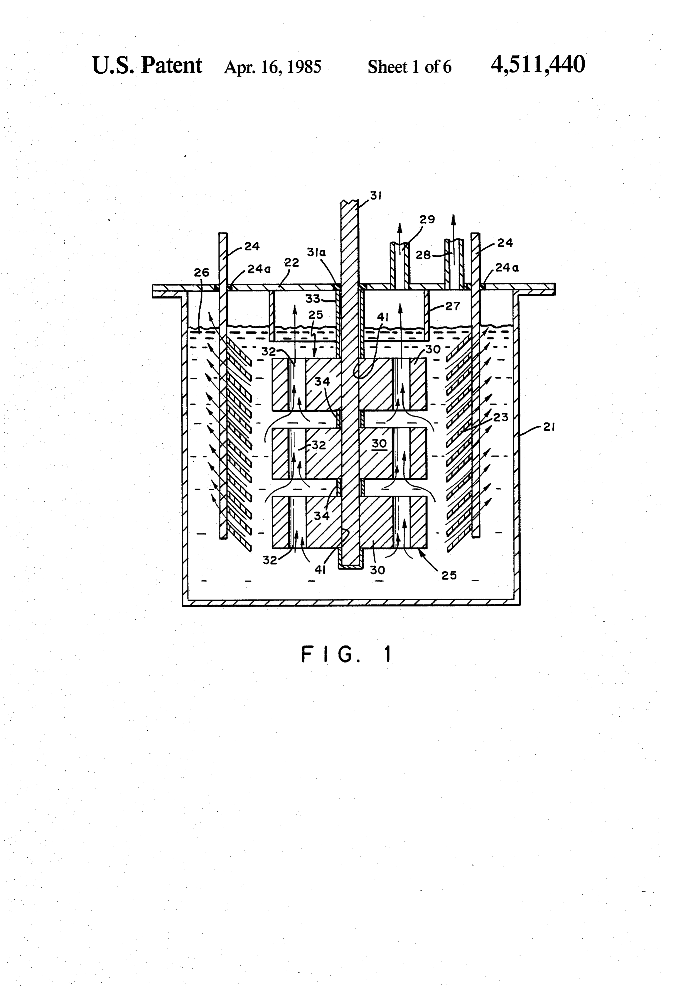
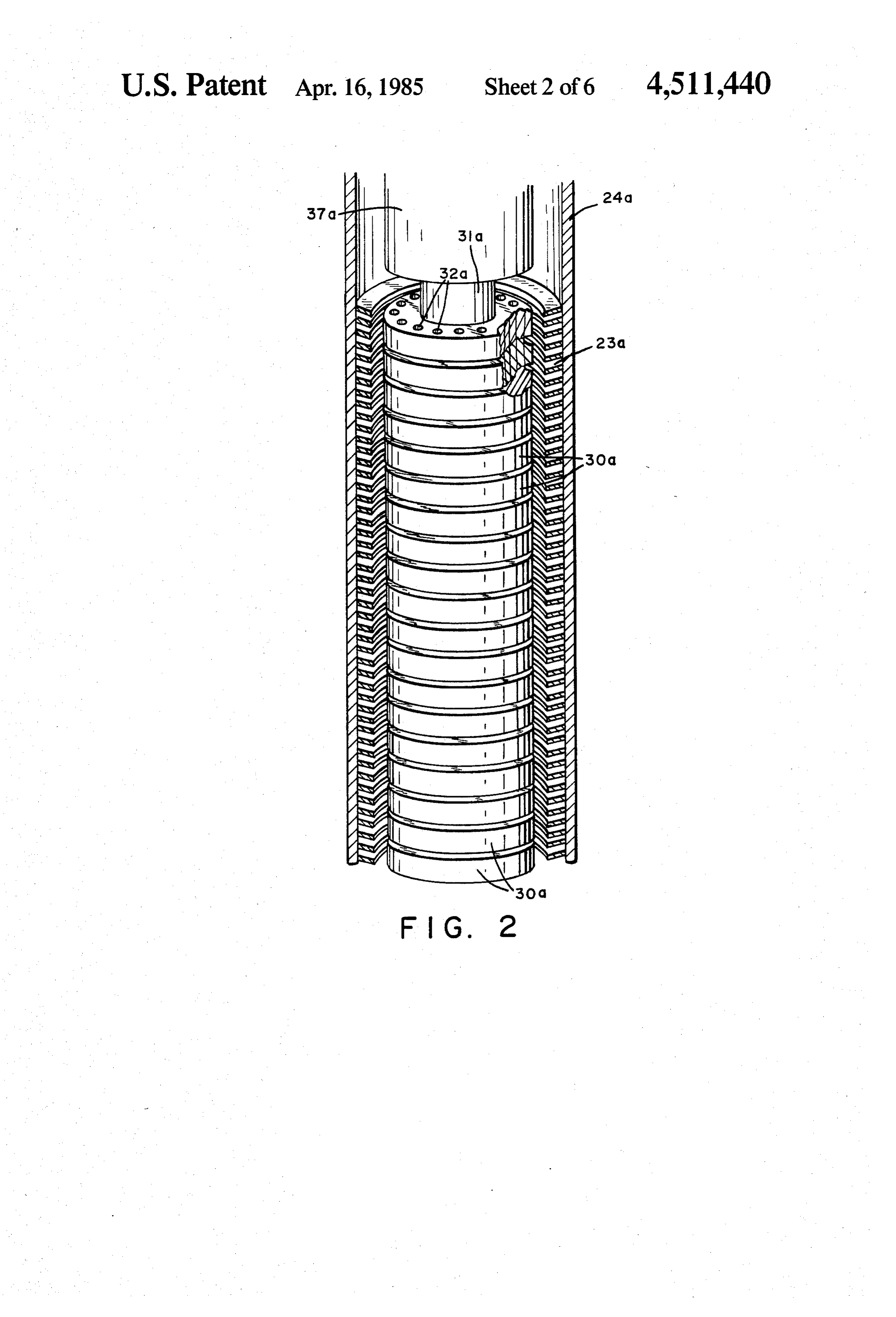
rine cell made according to the invention. 40 The embodiment illustrated in FIG. 2 depicts a full FIG. 2 illustrates partly in section the anode assembly scale solid carbon anode assembly comprising a plural with louvered cathode. ity of carbon plates 30a cut from a solid carbon block FIG. 3 is top view of one of the anode blades showing with passages 32a which serve as internal fluorine pas internal passages. sages. The cathode comprises the louvered structure FIG. 3a is a cross-section taken along line 3a-3a of 45 shown at 23a provided with the louvered cathode elec FIG, 3. trical contact 24a. Visible at the top of the anode 30a are FIG. 4 is top view of an alternate anode blade show the fluorine gas passages 32a. The anode is electrically ing a beveled periphery and showing, as well, an inter connected through the conductor 31a. A shirt or barrier 27a which collects the fluorine gas is suitably positioned nal passage.
FIG. 4a is a cross-sectional view taken along line 50 to Each confine the fluorine gas rising through passages 32a. carbon anode plate is of circular cross-section
FIG. 5 is top view of another embodiment showing a with a central hole for the conductor and other holes 32 which serve as internal fluorine passages. A side and a blade with a larger number of passages at various dis top view of a single carbon anode plate 30 is shown in tances from the working surface of the anode and show 55 FIGS.
ing, as well, a transverse passage for removal of fluorine serted in3athe and 3, respectively. The conductor 31 is in central hole 41, while fluorine gas escapes from the anode surface.
FIG. 5a is a cross-sectional view taken along line Sages. through holes 32 which serve as internal fluorine pas 5a-5a of FIG. 5. The edge 53 of the carbon plate can be beveled so FIG. 6 is top view of still another anode blade show 60 that it slopes away from the cathode (FIGS. 4 and 4a) ing extended transverse passages. or the top edge 54 of the anode can be tapered or FIG. 6a is a cross-sectional view taken along line rounded (FIGS. 5 and 5a). The bottom part 50 of a plate 6a-6a of FIG. 6. 30 can be made so that it will direct fluorine evolved on FIG. 7 illustrates for test purposes the taking of a slice the bottom of the anode centrally toward the internal of a blade. 65 fluorine passages 32 as shown in FIGS. (5a) and (6a). FIG. 7a is a perspective view of a segment taken from The carbon plate 30 may have one or several rows 46 of the slice of FIG. 7. internal fluorine passages 32. The anode 30 may also FIG. 8 illustrates the anode used in the test cell. have a groove 47 which cuts the anode into two or
Page 10
more blades. Thus, groove 47 connects the anode sur eral times and significantly reduce the anode-cathode face to the internal fluorine passages 32 (see FIGS. 5a distance, for example, to 5 mm. At the same time...it will and 6a). be possible to operate cell with very high surface anodic Due to the nonwetting surface of the carbon during current density, for example 1.2 A/cm2, while maintain normal electrolysis, fluorine creeps up the vertical elec 5 ing a low operating cell voltage without formation of an trode surface, travels around the shoulder of the carbon explosive mixture of hydrogen and fluorine and having plate and exits through the internal fluorine passages 32 a current efficiency of better than 90%. of the blade above it. This decreases the thickness of the It will be apparent that various forms of carbon can fluorine layer on the carbon surface of the anode, since be used in fabricating the carbon anode of the invention fluorine will exit internally and not over the electroac 10 Such as isotropic, anisotropic, dense, porous (or gas tive surface area. Each anode plate will primarily only permeably). It should be noted, however, that while the be masked by fluorine produced by that plate and not by advantages of porous or gas permeable carbon are de fluorine rising from other anode plates below it. As a scribed in many of the patents included such anodes result the voltage drop due to a fluorine layer on the possess also many disadvantages-such as poor lifetime, anode will be lower than for conventionally arranged 15 high cost, burning by fluorine, extreme difficulty in vertical anodes. making an effective anode-conductor contact. The cell Due to this design, the working surface of the anode design of the present invention has the advantages of assembly is several times larger than the vertical surface porous carbon-internal venting of fluorine gas, high area of a cylindrical anode facing the cathode since the surface area-but does not have the disadvantages asso fluorine evolution will not only occur on the surface 20 ciated with porous carbon since one can use dense car facing the cathode but also on the top and the bottom of bon with this design. Also, dense carbon is easier to each plate as well as inside the holes that form the inter attach to a conductor, has a long lifetime and is less nal fluorine passages. An arrangement of the kind pro expensive.
vided by the present invention permits operation at It will be understood that various other configura higher anodic current densities than conventional sys 25 tions of anode-contact other than a central conductor tems because the anodic system of the invention re may be employed. As such, for example are multiple moves fluorine as it is formed from the anodic surface. conductors, non-centered, exterior conductor, and the The basic idea of an anode which has the capability to like.
remove fluorine internally and has a much greater A feature at the anode design of the invention resides working surface than a conventional anode can be im 30 in the fact that the design decreases the thickness of the plemented in another way as shown in FIG. 11. The fluorine layer on the anode which makes possible lower anode, rather than being composed of separate plates, cell voltage. Since fluorine exits the anode internally it can be a solid rectangular block 60 with surface grooves does not break away from the anode frequently as free 6, to direct fluorine into the interior of the anode. bubbles. Hence the interelectrode gap can be decreased From these grooves 61 which effectively segment the 35 in length further lowering the cell voltage and energy anode, fluorine can exit through longitudinally drilled COSt.
holes 62 which serve as internal fluorine passage. The A further advantage resides in the fact that since a electrical contact arrangement is not shown. This anode similar electrolysis condition exists at each anode blade design has the same advantages as the anode design or segment, anode height is no longer a restriction as it described with reference to FIG. 1. 40 is in a conventional cell. Thus greater production can be A louvered cathode will permit most of the hydrogen achieved with less floor space in a plant. to be vented away from the zone between the elec The invention will be further described by reference trodes. This will significantly reduce the quantity of to the following specific example. It is to be understood, hydrogen bubbles in the electrolyte through which however, that although details are provided herein, current passes between the electrodes reducing the 45 these are given primarily for purposes of illustration and ohmic voltage loss. Said cathode, rather than being the invention in its broader aspects is not restricted louvered, can be expanded metal or one which consists thereto.
of punched sheet or gauze. If a plain sheet cathode is EXAMPLE I used, it may be necessary to increase anode-cathode separation. Clearly if this separation is inadequate, then 50 The cell used in this example and shown in FIG. 10 when high current density is employed, there is a possi reproduces in effect a cross-section of the upper portion bility of brisk evolution of hydrogen leading to crowd of the full size cell described above with reference to ing of hydrogen bubbles within this space, thus increas FIG. 1. The cell body is fabricated of two different ing the danger of hydrogen finding its way into the materials. The bottom 71 of the cell 70 and the two anode compartment. The anode, cathode and barrier 55 walls 72 are mild steel. The remaining two side walls, may be cylindrical in form although other geometrics i.e., the face and back of the cell are made of polymeth shapes, for instance, of rectangular or square section or ylpentene, a transparent plastic resistant to KF.2 HF, to even of hexagonal section may be used if desired. Vari permit observation of gas and melt circulation within ous metals may be employed in fabricating the cathode. the cell. The cell is fitted with an anode 74, and mild Thus, for example, in addition to mild steel, nickel or 60 steel louvered cathode 75. Surrounding the upper part copper or their alloys, such as monel, and the like, may of the anode assembly and which dips into electrolyte be used. 76 is a skirt or barrier 77. The skirt 77, as well as, the top The combination of the segmented anode design with or lid 77a of the cell 70 is formed of a suitable metal a gas directing louvered or expanded metal cathode will which is resistant to fluorine such a magnesium, monel create a unique cell for fluorine production because it is 65 metal and the like. Clearance between these parts and expected that virtually the same electrolysis condition the cell plastic walls is kept to a minimum in order to will exist at any part of the anode and cathode. It will be prevent current paths to the side and back of the anode, possible to increase the anode and cathode length sev and to prevent melt circulation past the edges of the
Page 11
electrodes. Thus, current distribution and mass trans rine as free bubbles at the vertical carbon surface was port will be similar to that in the larger cell of this de observed.
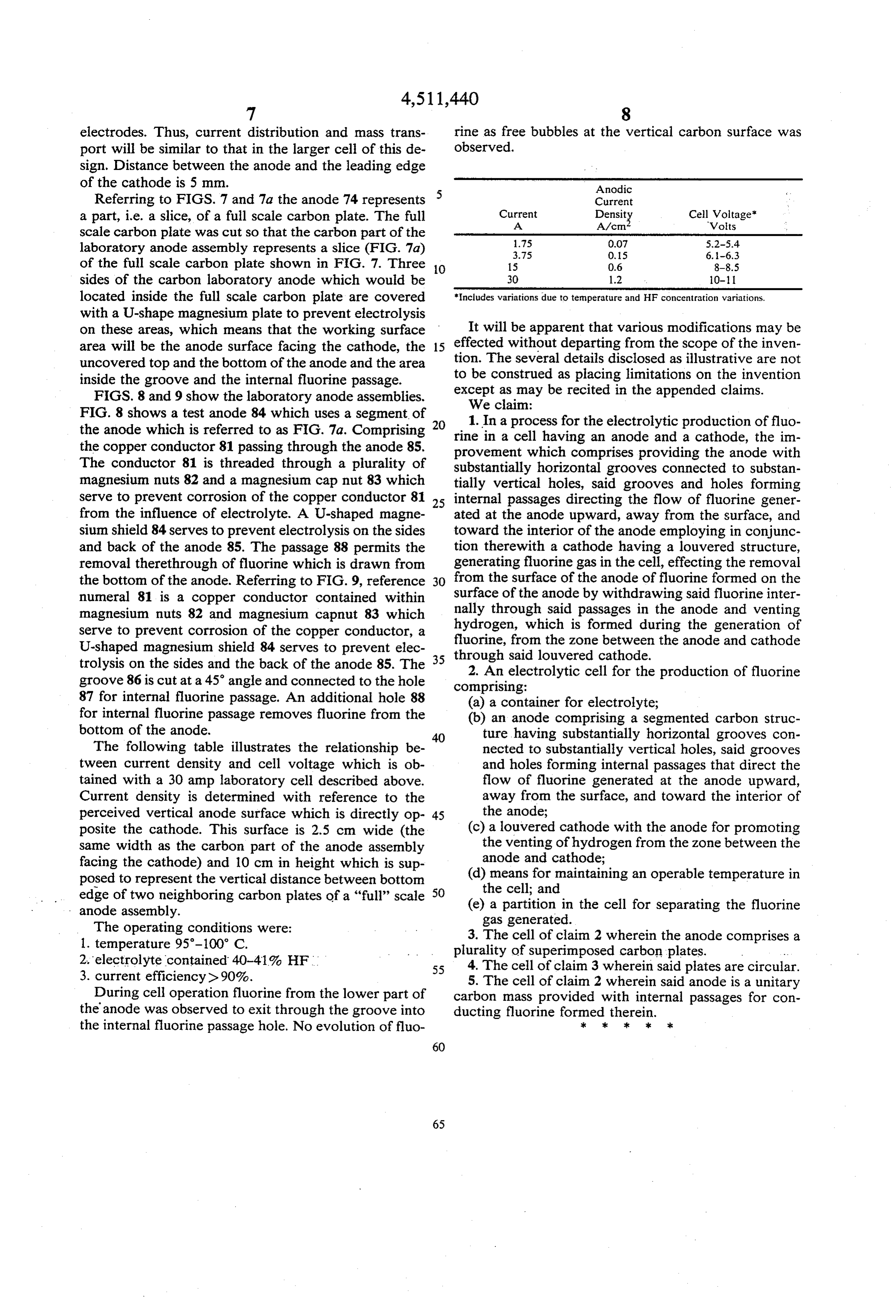
sign. Distance between the anode and the leading edge of the cathode is 5 mm. Anodic Referring to FIGS. 7 and 7a the anode 74 represents Current a part, i.e. a slice, of a full scale carbon plate. The full Current Densit Cell Voltage"
scale carbon plate was cut so that the carbon part of the 1.75 0.07 5.2-5.4 laboratory anode assembly represents a slice (FIG. 7a) 3.75 O.15 6.-6.3 of the full scale carbon plate shown in FIG. 7. Three 10 15 0.6 8-8.5 sides of the carbon laboratory anode which would be 30 1.2 10-11 located inside the full scale carbon plate are covered *Includes variations due to temperature and HF concentration variations. with a U-shape magnesium plate to prevent electrolysis on these areas, which means that the working surface It will be apparent that various modifications may be area will be the anode surface facing the cathode, the 15 effected without departing from the scope of the inven uncovered top and the bottom of the anode and the area tion. The several details disclosed as illustrative are not inside the groove and the internal fluorine passage. to be construed as placing limitations on the invention FIGS. 8 and 9 show the laboratory anode assemblies. except as may be recited in the appended claims. We claim:
FIG. 8 shows a test anode 84 which uses a segment of the anode which is referred to as FIG. 7a. Comprising 20 rine1. Inin a process for the electrolytic production of fluo a cell having an anode and a cathode, the im the copper conductor 81 passing through the anode 85. provement which comprises providing the anode with The conductor 81 is threaded through a plurality of substantially horizontal grooves connected to substan magnesium nuts 82 and a magnesium cap nut 83 which tially vertical holes, said grooves and holes forming serve to prevent corrosion of the copper conductor 81 25 internal passages directing the flow of fluorine gener from the influence of electrolyte. A U-shaped magne ated at the anode upward, away from the surface, and sium shield 84 serves to prevent electrolysis on the sides toward the interior of the anode employing in conjunc and back of the anode 85. The passage 88 permits the tion therewith a cathode having a louvered structure, removal therethrough of fluorine which is drawn from generating fluorine gas in the cell, effecting the removal the bottom of the anode. Referring to FIG. 9, reference 30 from the surface of the anode of fluorine formed on the numeral 81 is a copper conductor contained within surface of the anode by withdrawing said fluorine inter magnesium nuts 82 and magnesium capnut 83 which nally through said passages in the anode and venting hydrogen, which is formed during the generation of serve to prevent corrosion of the copper conductor, a fluorine,
U-shaped magnesium shield 84 serves to prevent elec through said from the zone between the anode and cathode trolysis on the sides and the back of the anode 85. The 35 louvered cathode. 2. An electrolytic cell for the production of fluorine groove 86 is cut at a 45° angle and connected to the hole comprising:
87 for internal fluorine passage. An additional hole 88 (a) a container for electrolyte; for internal fluorine passage removes fluorine from the (b) an anode comprising a segmented carbon struc bottom of the anode. 40 ture having substantially horizontal grooves con The following table illustrates the relationship be nected to substantially vertical holes, said grooves tween current density and cell voltage which is ob and holes forming internal passages that direct the tained with a 30 amp laboratory cell described above. flow of fluorine generated at the anode upward, Current density is determined with reference to the away from the surface, and toward the interior of perceived vertical anode surface which is directly op 45 the anode;
posite the cathode. This surface is 2.5 cm wide (the (c) a louvered cathode with the anode for promoting same width as the carbon part of the anode assembly the venting of hydrogen from the zone between the facing the cathode) and 10 cm in height which is sup anode and cathode;
posed to represent the vertical distance between bottom (d) means for maintaining an operable temperature in edge of two neighboring carbon plates of a “full” scale 50 (e)the cell; and a partition in the cell for separating the fluorine anode assembly. gas generated.
The operating conditions were: 3. The cell of claim 2 wherein the anode comprises a 1. temperature 95-100° C. plurality of superimposed carbon plates. 2. electrolyte contained 40-41% HF 55 4. The cell of claim 3 wherein said plates are circular. 3. current efficiency).90%. 5. The cell of claim 2 wherein said anode is a unitary During cell operation fluorine from the lower part of carbon mass provided with internal passages for con the anode was observed to exit through the groove into ducting fluorine formed therein.
the internal fluorine passage hole. No evolution of fluo k sk k ck k
Page 12
UNITED STATES PATENT AND TRADEMARK OFFICE
CERTIFICATE OF CORRECTION
A. M. Saprokhin D. J. Friedland, R. M. Baran, J. T. Kirn, and L. E. McCurry it is certified that error appears in the above-identified patent and that said Letters Patent are hereby Corrected as shown below:
Front Page, Filing date, "Dec. 27, 1983" should read
eigned and Sealed this
SEAL
Fifteenth Day of October 1985
Attest:
DONALD.J. QUIGG
Attesting Officer Commissioner of Patents and
Provenance
- Collection
- Cited prior art
- Original PDF
- patentimages.storage.googleapis.com →
- Filed
- 1983-12-22
- Pages
- 12
- Method
- pdftotext (the PDF's own text layer) + pdftoppm 300dpi page scans
- Source
- Google Patents bibliographic record
- Granted
- 1985-04-16
- Inventors
- Alexander M. Saprokhin; David J. Friedland; Richard M. Baran; Jung T. Kim; Lynn E. McCurry; Allied Corp
- Transcribed from
- patentimages.storage.googleapis.com →