patent · US5273635
Electrolytic heater
28 December 1993
Page 1 — bibliographic record
United States Patent (19) 11) Patent Number: 5,273,635 Gernert et al. 45) Date of Patent: Dec. 28, 1993 (54) ELECTROLYTIC HEATER 3,877,989 4/1975 Waldman et al. ............ 204/DIG. 6
(75) Inventors: Nelson J. Gernert, Elizabethtown; 4,206,08 6/1980 Kreisel et al. .................. 204/24 X Robert M. Shaubach, Litiz; Donald 4,336,122 6/1982 Spirig .................. ... 204/274 X M. Ernst, Leola, all of Pa. 4,420,381 12/1983 Silvotti et al... ... 204/274 X 73 irraa. 4,749,463 6/1988 Holmen ............................... 204/241 Assignee: Thermacore, Inc., Lancaster, Pa. 4,872,957 10/1989 Dong et al. . ... 204/283 21 Appl. No.: 894,287 4,911,803 3/1990 Kunz ............... ... 204/283 4,931,168 6/1990 Watanabe et al. ... 204/283 (22 Filed: Jun. 4, 1992 4,980,037 2/1990 Hossain et al. ...................... 204/283 5,089,107 2/1992 Pacheco .......................... 204/241 X 51) Int. Cl.......................... C25B 9/00; C25B 15/08 A1992 Pacheco W 52 U.S.C. .................................... 204/241; 204/274; Primary Examiner-Donald R. Valentine 204/275; 204/277; 204/278; 204/290 F; Attorney, Agent, or Firm-Martin Fruitman
58) Field of Search ............ 204/241, 242, 274, 290 F, (57) ABS CT 204/292, 275-278 A heater which uses the electrolysis of a liquid to pro duce heat from electricity and transfers the heat from (56) References Cited the electrolyte by means of a heat exchanger. One em
and an electrolyte of potassium carbonate with a heat exchanger immersed in and transferring heat from the 2,098,629 1/1937 Knowlton ..................... 204/DIG 6 electrolyte.
3,104,308 9/1963 Wilson ............................ 204/275 X 3,131,135 4/1964 Coopersmith .................. 204/274 X 12 Claims, 3 Drawing Sheets
w ER É 2 32 war |- r1 -
48 O AS 24 3O S. O C
NASO 8&N-28
R21 2
NNNNNNNNNNS
Page 2
Drawing sheet — no readable text.
Page 3
Drawing sheet — no readable text.
Page 4
Drawing sheet — no readable text.
Page 5
With heat being generated directly at the interface
ELECTROLYTIC HEATER between the electrolyte and electrodes, it is only neces sary to transfer heat from the electrolyte, and, as is well
SUMMARY OF THE INVENTION understood by those skilled in the art of heat transfer, This invention deals generally with electrolysis and 5 liquid to liquid heat transfer is much easier to accom more specifically with a device which produces usable plish than gas to liquid heat transfer. Therefore, in the preferred embodiment, a heat ex heat within an electrolytic cell.
changer is constructed within the electrolyte tank by
While it is generally understood that heat generation forming is one of the results of electrolysis, the process of elec O To a coil of pipes around the group of electrodes. trolysis has only been used for heat generation in a prevent corrosion of the pipes by the electrolyte, the somewhat secondary manner. There have been some pipes of the preferred embodiment are constructed of devices which generate hydrogen and oxygen by elec polyethylene, or at least coated with a material which prevents the corrosive effects. A heat exchange fluid is trolysis and then combine them to create heat in a differ then pumped through the coiled pipes to transfer heat ent locale, thus permitting the movement of the gases to 15 from the electrolyte to any other location. A preferred substitute for heat transfer.
However, the present invention uses electrolysis to heat exchange fluid is water, which can not only be used in all conventional pipes, but the hot water pro generate heat directly, and uses heat exchangers to duced within the electrolytic cell can be used directly transfer the heat generated from one or more electro for household or industrial purposes. It should also be lytic cells to other locations or heat transfer mediums where it is used conventionally. One of the advantages 20 understood that multiple cells can be arranged in a of such a system is that the generation of heat can take group The to increase the heat available.
electrolytic cell also includes a conventional place at lower temperatures than are customarily used hydrogen recombiner to prevent hydrogen gas build in electrical resistance or combustion heating systems, up, and since this hydrogen combiner also generates thereby reducing the likelihood of the combustion of 25 some heat, the water it produces is drained back into the surrounding materials and enhancing fire safety. How electrolyte to conserve that heat within the cell. ever, the temperature can also be raised by permitting One alternate embodiment for the removal of heat the cell to operate at a higher internal pressure, so that the electrolytic cell heat generator has a greater versa from outside the electrolytic cell is a heat exchanger on the of the tank which requires no special accommo tility than most heaters. 30 dation to prevent corrosion by the electrolyte. In such Another advantage is the direct generation of heat an arrangement, the tank of the electrolytic cell isolates within a liquid. This permits the very efficient transfer the of heat from one liquid, the electrolyte, to another liq the pipes of the heat exchanger from the electrolyte, but walls of the tank can be constructed of materials and uid, such as water, without an intermediate step of heat thicknesses which still permit efficient heat transfer ing gases as occurs in the typical combustion process. 35 through them to the heat exchanger fluid in the pipes. The preferred embodiment of the present invention Still another method of utilizing the heat of the elec includes an electrolytic cell constructed of materials trolytic cell is to pump the electrolyte to a remote loca which yield a very high efficiency of heat generation tion where it can be passed directly through a heat within the electrolytic cell. A heat exchanger is im exchanger.
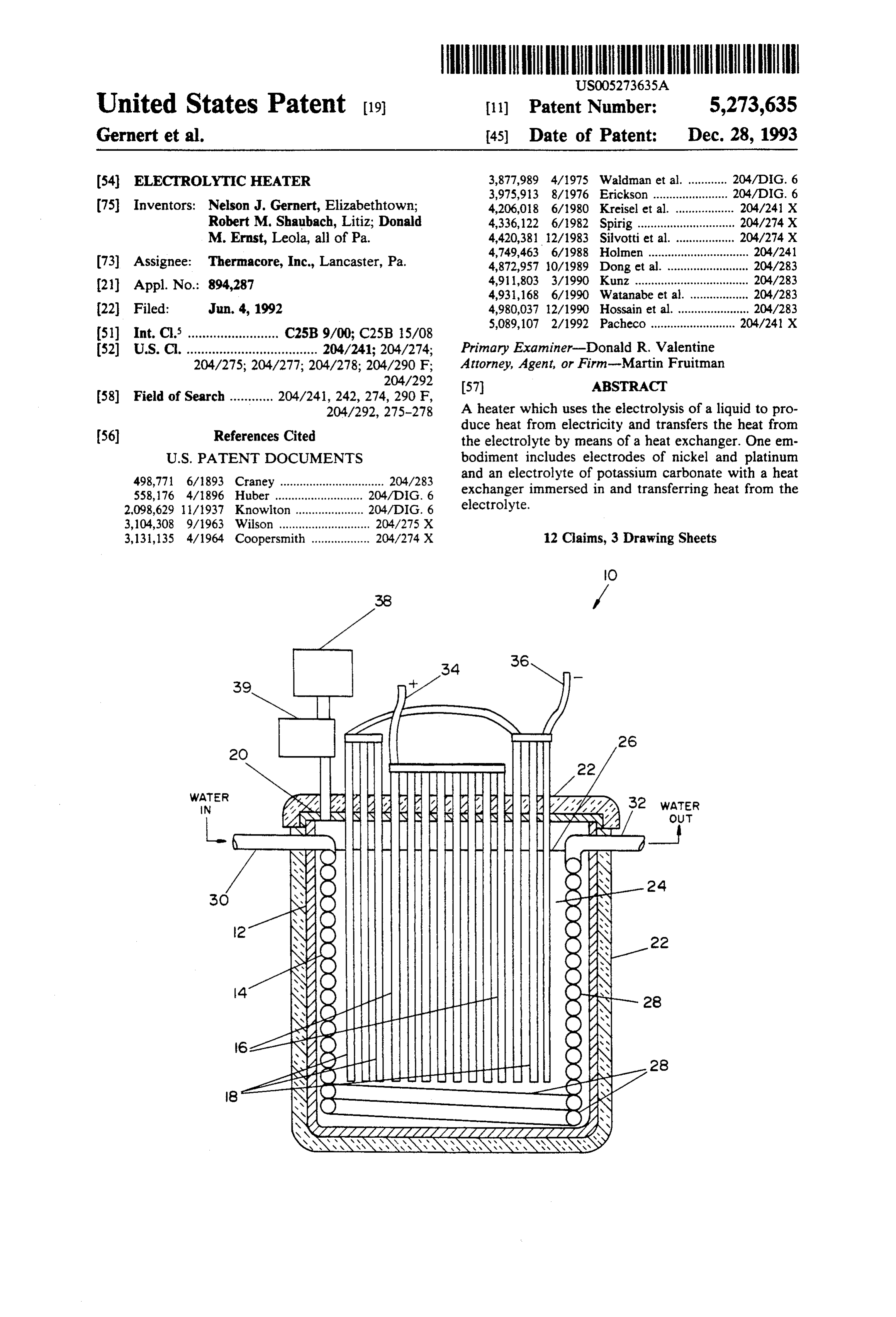
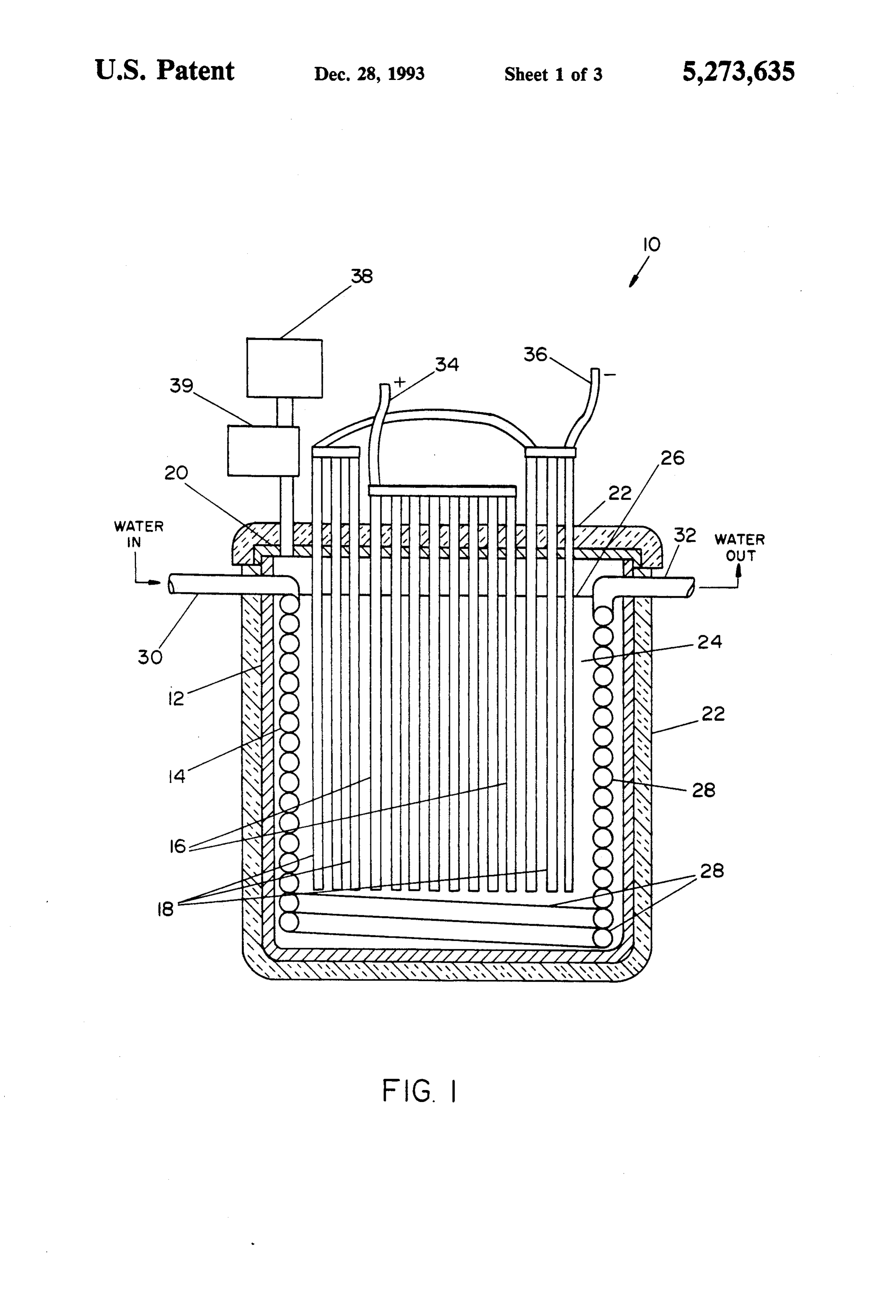
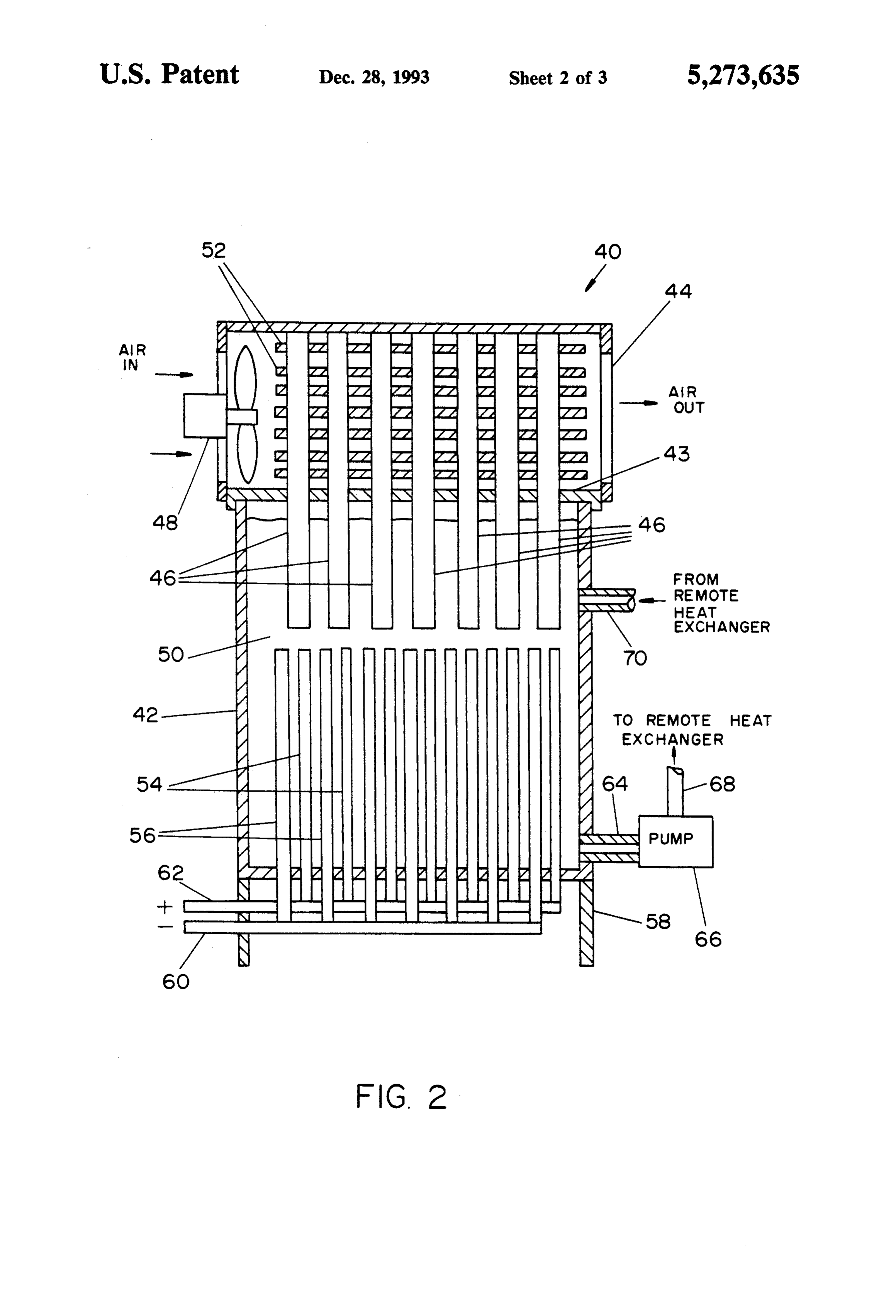
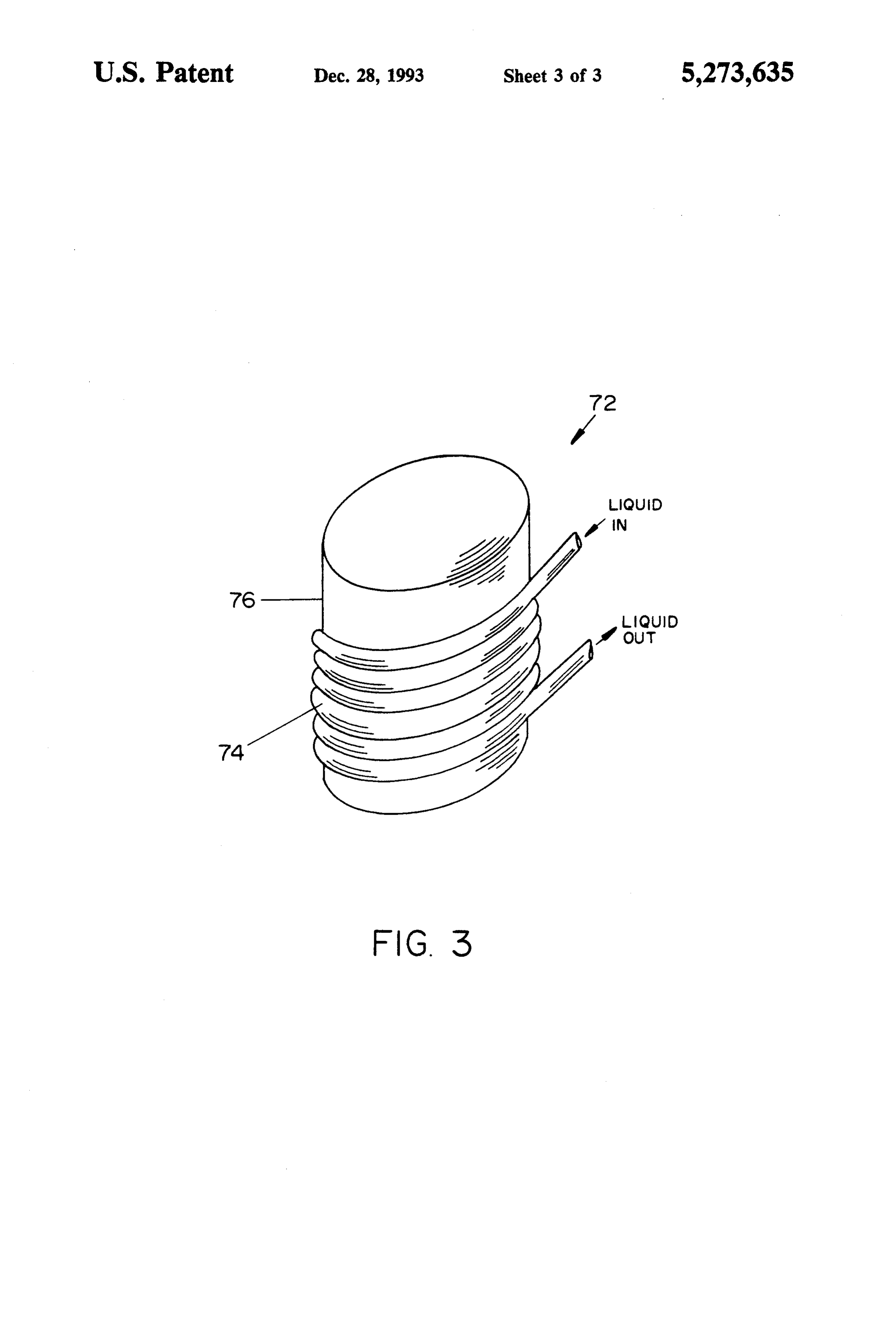
mersed directly within the electrolyte, and the heat The present invention therefore furnishes a very effi exchanger and can be used directly circulated through cient and safe heating system, and as with most electri the heat exchanger and can be used directly as a source cally powered heaters, it can be installed in large sizes as of hot water or can be pumped to a conventional finned a central heating unit or can be used as a localized heat heat exchanger to heat a remote location. source in smaller sizes. It is, however, particularly well The electrolytic cell of the preferred embodiment has 45 suited as a water heater or furnace. a nickel cathode, an anode constructed of platinum coated titanium, and an electrolyte of potassium carbon BRIEF DESCRIPTION OF THE DRAWINGS ate. Recent studies indicate that this combination of FIG. 1 is a partial cross section view of the electro materials produces heat within the cell with extremely lytic cell of the preferred embodiment of the invention high efficiency, so that all the electrical power input 50 as it is used to heat water.
into the cell is converted to usable heat. FIG. 2 is a partial cross section view of an alternate A preferred embodiment of the electrolytic heating embodiment of the invention as it is used to warm air. apparatus includes an insulated polyethylene tank con FIG. 3 is a perspective view of a simple liquid heat taining potassium carbonate electrolyte with wire or exchanger installed on the exterior surface of an electro rod electrodes penetrating a removable cover of the 55 lytic cell.
tank, and large portions of the electrodes immersed in DETAILED DESCRIPTION OF THE the potassium carbonate. Approximately one-half of the INVENTION electrodes are nickel and are used as the cathodes of the cell, while the remainder of the rods are platinum FIG. 1 is a partial cross section view of the preferred coated titanium and are connected to act as the anodes. embodiment of the invention in which electrolytic cell Electrical connections to the electrodes are made on 10 is shown with pressure sealed tank 12 in a partial the outside of the tank, and the direct current voltage sectional view so that the internal assembly of heat applied is approximately five volts. This low voltage is exchanger 14, anodes 16 and cathodes 18 may be seen another factor in enhancing safety, since authorities clearly.
consider it well below any level of danger from electri 65 Tank 12 is constructed of a corrosion resistant mate cal shock. Of course, since power must be furnished by rial such as polyethylene, or is at least coated with such means of high current, heavy conductors are used to a material on its inside surfaces, and is pressure sealed connect to the electrodes. by cover 20 through which anodes 16 and cathodes 18
Page 6
penetrate. Both tank 12 and cover 20 are covered by should also be appreciated that while the preferred heat insulating material 22 to prevent incidental heat configuration for the tanks shown in all the figures may loss from electrolytic cell 10. Tank 12 contains liquid be cylindrical, virtually any shape liquid container is electrolyte 24 to approximately level 26, so that electro satisfactory.
lyte 24 covers most of heat exchanger 14, anodes 16 and Electrolytic cell 42 includes heat exchanger 44 which cathodes 18. transfers heat from the electrolyte of cell 40 to heat Heat exchanger 14 is constructed as a continuous coil pipes 46 and then to air being moved through heat ex of pipes 28 through which a liquid heat exchanger fluid, changer 44 by fan 48. Heat pipes 46 are immersed in preferably water, is pumped by an outside device such electrolyte 50 in tank 42 and move the heat from as a pump (not shown). Liquid is fed into heat ex 10 warmer electrolyte 50 to cooler cooling fins 52 by the changer 14 at pipe 30 and leaves heat exchanger 14 at well known process of evaporation and condensation pipe 32 after having moved though the entire heat ex changer. Heat transfer takes place within tank 12 di within the heat pipes.
As in the electrolytic cell of FIG. 1, heat is generated rectly from electrolyte 24 to the liquid flowing in heat within electrolytic cell 40 by the electrolytic action of a exchanger 14 through only the thin walls of heat ex 15 D.C. voltage applied between anodes 54 and cathodes changer pipes 28. This heat is originally generated by 56, but by means of heat pipes 46 and heat exchanger 44 the electrolytic action caused by a direct current volt the heat is transferred age applied across anodes 16 and cathodes 18 when they used to heat a room or to an air stream which can be other enclosed space.
are immersed in electrolyte 24. The electrical connec tions are made at positive connection 34 and negative 20 tionRegardless of whether the ultimate use of the inven is to heat a liquid, as shown in FIG. 1, or a gas, as connection 36.
Heat generation by electrolytic action is particularly shown in FIG. 2, a simple means to control the tempera efficient when the combination of certain materials is ture at which the electrolytic cell will operate, below used. One such combination, which is used in the pre the maximum temperature determined by the pressure ferred embodiment, is an electrolyte of potassium car 25 within the tank, is to interrupt the removal of heat from bonate, anodes of platinum coated titanium and cath the cell by a thermostatic device. This can be done by odes of nickel. stopping or reducing the flow of liquid through heat One desirable configuration for the cathodes 18 is a exchanger 14 of FIG. 1 or by simply stopping fan 48 in polished wire or rod constructed by sintering 300 mesh FIG. 2. In either case the result would be an increase in nickel powder with smooth particles. This structure temperature in the electrolytic cell until the fluid flow is provides a large surface area with small nucleation site reestablished.
radii for generation of hydrogen gas. Heat generation In the alternate embodiment of FIG. 2, tank 42 is essentially takes place at the location where hydrogen elevated on support structure 58 so that electrical con gas is created, and heat generation is enhanced by the nections 60 and 62 can be connected to anodes 54 and polished surface. 35 cathodes 56 at the bottom of tank 42. This configuration The positive voltage is applied to the anode from a permits the heat exchanger to be located on top of the conventional source (not shown) and, for the materials tank, but it would be possible to reverse the locations of of the preferred embodiment, is approximately five the electrical connections and the heat exchanger, or volts. even to locate them both at the top of the tank. FIG. 1 also depicts a typical location for hydrogen 40 The configuration of FIG. 2 is particularly advanta recombiner 38 and pressure regulator 39 connected at geous for a portable room heater since the normal oper the top of tank 12. Hydrogen recombiner 38 is a con ating temperature of even the hottest part of the appara ventional device which recombines the hydrogen and tus can be limited to be well below the combustion oxygen which are the result of the electrolytic process, temperature of common household materials such as and the resulting water returns any heat generated dur 45 ing the recombination process to the electrolyte from paper and cloth.
which the heat will be transported along with the rest of from cell2 also
FIG.
depicts another means for removing heat by simply pumping heated electrolyte 50 the heat generated.
Pressure regulator 39 is the means by which the maxi distribution pipe 68 to aoutput
remote heat exchanger (not mum temperature of operation of electrolytic cell is 50 shown). The cooled electrolyte is then controlled. With an open tank and without pressure 42 by return pipe 70 for reheating. returned to cell regulator 39 the electrolyte would boil at a particular temperature determined by its chemical constituents tusFIG. 3 depicts what is probably the simplest appara and the atmospheric pressure, and no further increase in involvestransferring for heat from an electrolytic cell. It temperature would occur. Pressure sealed tank 12 and 72 around electrolytic cella74coiled 55 simply wrapping heat exchanger pipe and insulating the entire pressure regulator 39 permit the pressure within the cell to rise, the pressure rise being driven by the generation structure. While this arrangement requires heat conduc of gases from the electrolytic process, and as the pres tion through tank 76, proper selection of the material sure rises, the boiling temperature of the electrolyte also and thickness of tank 76 can provide for very effective rises. Pressure regulator 39 can be adjusted to relieve 60 heat transfer.
the built up pressure at any preset value and will It is to be understood that the form of this invention thereby control the maximum temperature of cell oper as shown is merely a preferred embodiment. Various ation. changes may be made in the function and arrangement FIG. 2 is a partial cross section view of electrolytic of parts; equivalent means may be substituted for those cell 40 in which tank 42 is shown in partial cross section 65 illustrated and described; and certain features may be so that the internal structure of the cell may be seen. used independently from others without departing from Normally tank 42 and cover 43 would be covered by the spirit and scope of the invention as defined in the heat insulation, but that has been omitted for clarity. It following claims.
Page 7
For example, other electrolytes, such as rubidium 9. The electrolytic cell of claim 1 wherein the tank carbonate, can also be used, as can other materials for includes sealing means to permit pressurization of the the electrodes. tank.
What is claimed as new and for which Letters Patent 10. The electrolytic cell of claim 1 wherein the tank of the United States are desired to be secured is: includes sealing means to permit pressurization of the 1. A heat generating electrolyte cell comprising: tank and a pressure regulator attached to the tank which a tank constructed of corrosion resistant material, the permits raising the gas pressure within the tank to se tank being constructed to be able to contain a liquid lected pressures above atmospheric pressure. electrolyte and including a sealed access cover 11. A heat generating electrolytic cell comprising: which prevents the escape of gases from the tank; O a tank constructed of corrosion resistant material, the at least one anode electrode within the tank and lo tank being constructed to be able to contain a liquid cated so that it contacts electrolyte when contained electrolyte and including a sealed access cover within the tank; which prevents the escape of gases from the tank; an electrical connection attached to each anode elec at least one anode electrode within the tank and lo trode which supplies each anode electrode with a 15 cated so that it contacts electrolyte when contained positive voltage; within the tank;
at least one cathode electrode within the tank and an electrical connection attached to each anode elec located so that it contacts electrolyte when con trode which supplies each anode electrode with a tained within the tank; positive voltage;
an electrical connection attached to each cathode 20 at least one cathode electrode within the tank and electrode which supplies each cathode electrode located so that it contacts electrolyte when con with a negative voltage; tained within the tank;
a heat transfer means located so that it is in thermal an electrical connection attached to each cathode contact with liquid electrolyte when contained electrode which supplies each cathode electrode within the tank and functioning to transfer heat 25 with a negative voltage; and generated within the electrolytic cell to a location at least one heat pipe extending into a heat exchanger outside the cell; and and located so that it is in thermal contact with heat insulation covering the outside surfaces of the liquid electrolyte when contained within the tank, tank. the heat pipe functioning to transfer heat generated 2. The electrolytic cell of claim 1 further including a 30 within the electrolytic cell to the heat exchanger. hydrogen recombining means interconnected with the 12. A heat generating electrolytic cell comprising: interior of the tank. a tank constructed of corrosion resistant material, the 3. The electrolytic cell of claim 1 wherein the heat tank being constructed to be able to contain a liquid transfer means is a coil of pipes through which is electrolyte and including a sealed access cover pumped a liquid heat exchanger fluid, the coil of pipes 35 which prevents the escape of gases from the tank; being located within the tank so that it surrounds the at least one anode electrode within the tank and lo anode and cathode electrodes within the tank. cated so that it contacts electrolyte when contained 4. The electrolytic cell of claim 1 wherein the heat within the tank;
transfer means is a pump which, when electrolyte is an electrical connection attached to each anode elec contained within the tank, moves the heated electrolyte trode which supplies each anode electrode with a to a remote location where heat may be removed from positive voltage;
the electrolyte. at least one cathode electrode within the tank and 5. The electrolytic cell of claim 1 wherein the anode located so that it contacts electrolyte when con electrodes are constructed of platinum coated titanium. tained within the tank;
6. The electrolytic cell of claim 1 wherein the cath 45 an electrical connection attached to each cathode ode electrodes are constructed of nickel. electrode which supplies each cathode electrode 7. The electrolytic cell of claim 1 wherein the cath with a negative voltage; and ode electrodes are constructed of sintered nickel. a configuration of pipe external to the tank and in 8. The electrolytic cell of claim 1 wherein the cath thermal contact with the tank through which is ode electrodes are constructed of polished sintered 50 pumped a liquid heat exchanger fluid. nickel.
Provenance
- Collection
- Cited prior art
- Original PDF
- patentimages.storage.googleapis.com →
- Filed
- 1992-06-04
- Pages
- 7
- Method
- pdftotext (the PDF's own text layer) + pdftoppm 300dpi page scans
- Source
- Google Patents bibliographic record
- Granted
- 1993-12-28
- Inventors
- Nelson J. Gernert; Robert M. Shaubach; Donald M. Ernst; Thermacore Inc
- Transcribed from
- patentimages.storage.googleapis.com →