patent · US3779811
Matrix-type fuel cell
18 December 1973
Page 1 — bibliographic record
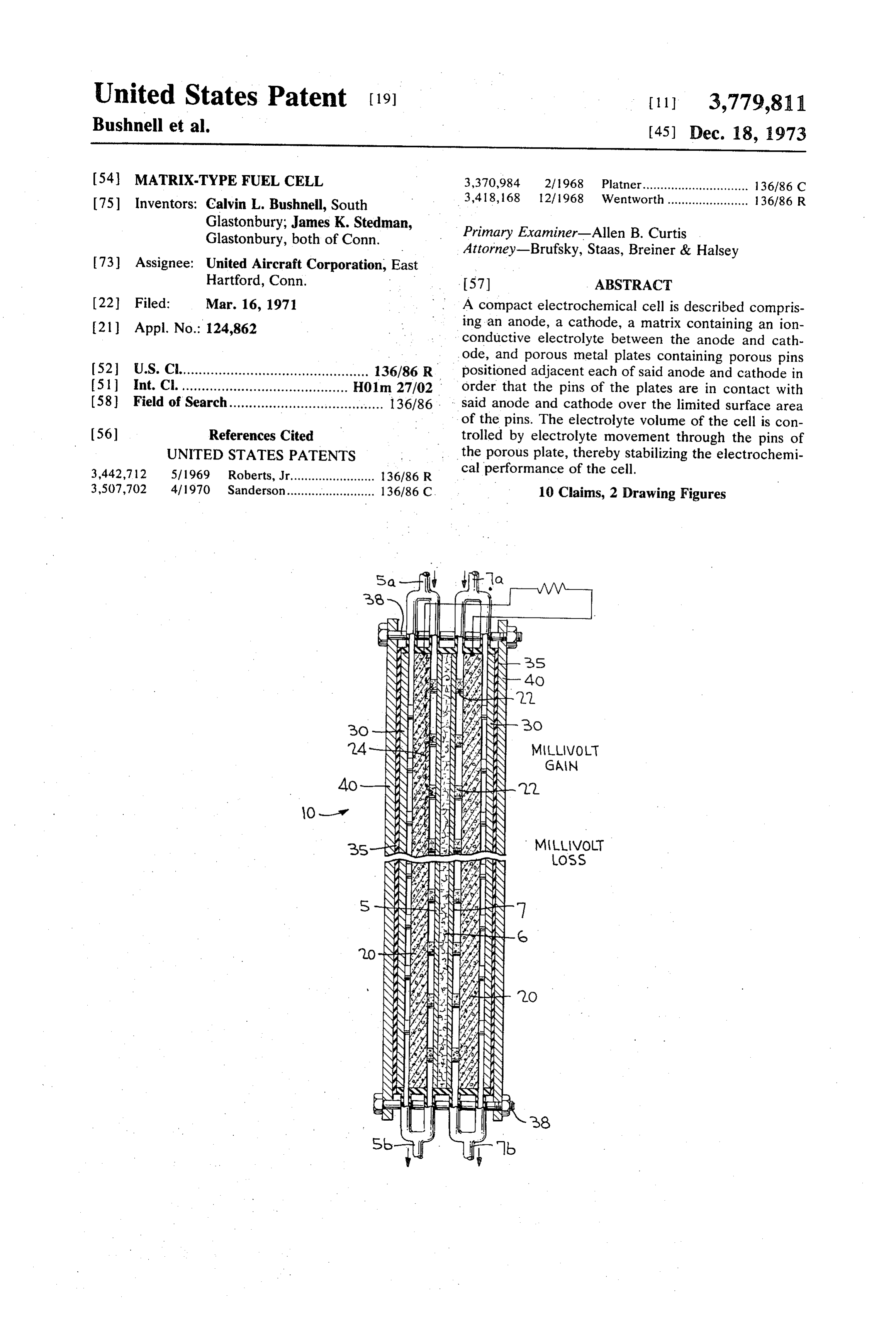
United States Patent (19 [11] 3,779,811 Bushnell et al. (45) Dec. 18, 1973 (54) MATRIX-TYPE FUEL CELL 3,370,984 2/1968 Platner.............................. 136/86 C (75) Inventors: Calvin L. Bushnell, South 3,418, 168 12, 1968 Wentworth....................... 136/86 R Glastonbury; James K. Stedman, Primary Examiner-Allen B. Curtis
Glastonbury, both of Conn. Attorney-Brufsky, Staas, Breiner & Halsey 73) Assignee: United Aircraft Corporation, East
Hartford, Conn. . 57) ABSTRACT 22 Filed: Mar. 16, 1971 A compact electrochemical cell is described compris 21) Appl. No.: 124,862 ing an anode, a cathode, a matrix containing an ion conductive electrolyte between the anode and cath ode, and porous metal plates containing porous pins 52 U.S. Cl................................................ 136/86 R. positioned adjacent each of said anode and cathode in (5) Int. Cl. .......................................... H01m 27/02 order that the pins of the plates are in contact with (58) Field of Search............. . . . . . . . . . . . . . . . . . . . . . . . . . . 136/86. - said anode and cathode over the limited surface area of the pins. The electrolyte volume of the cell is con (56) References Cited trolled by electrolyte movement through the pins of UNITED STATES PATENTS the porous plate, thereby stabilizing the electrochemi 3,442,712 5/1969 Roberts, Jr........................ 136/86 R cal performance of the cell. 3,507,702 4/1970 Sanderson......................... 136/86 C. 10 Claims, 2 Drawing Figures
24-NN 3. % NN MLVOLT
Page 2
PATENTED DEC 181973 3,779,8ll
Hill i + |- 2 --
SoZl --- v?. - Q- -
Od O (N O C - C N
assassassists saias
Wawa Avatawawa AA
Page 3
MATRIX-TYPE FUREL CELL
OBJECTS OF THE INVENTION AND GENERAL
FIELD OF INVENTION AND BACKGROUND DESCRIPTION
This invention relates to electrochemical cells and, Accordingly, a primary object of the present inven more particularly, to an improvement in an electro 5 tion is to provide a cell design which separates the vol chemical cell utilizing an electrolyte contained in, or ume tolerance function from the electrochemical func trapped in a matrix between the electrodes of a cell tion of the cell.
whereby the volume of the electrolyte is controlled, Another object of the present invention is to provide stabilizing cell performance. For convenience, herein a matrix-type fuel cell which permits convenient re after the invention will be described with reference to 10 moval of excess liquid, preventing flooding of the elec a fuel cell for the direct generation of electricity utiliz trodes.
ing two non-consumable electrodes. As will be appar Another object of this invention is to provide a ma ent, however, similar considerations governing the use trix-type fuel cell which permits convenient replenish of the invention in such cells will apply to other electro ing of electrolyte, preventing matrix/electrode dry-out. chemical devices such as electroylzers enabling its use 15 Another object of this invention is to provide a ma in such devices. trix-type fuel cell having an electrolyte reservoir which A fuel cell, as the term is employed herein, designates will automatically control the electrolyte volume in the an electrochemical cell for the direct production of cell matrix.
electrical energy from a fuel and oxidant. With such Another object of this invention is to provide a ma cells, it is not necessary to go through the usual conver 20 trix-type fuel cell having improved cell spacing. sion of chemical energy to heat energy to mechanical Another object of this invention is to provide a ma energy to electrical energy as is common with heat en trix-type fuel cell having a low IR loss. gines. Such cells in their most simplified design com These and other objects of the invention will be more prise a housing, an oxidizing electrode, a fuel electrode, readily apparent from the following detailed descrip and an electrolyte. In operation, it is necessary that the 25 tion, with particular emphasis being placed on the em fuel and oxidant contact a surface of their respective bodiment illustrated in the drawing. electrode where a process of adsorption and de In accordance with the present invention, a matrix adsorption occurs leaving the electrodes electrically type fuel cell is constructed which incorporates a po charged, with the second surface of the electrodes rous plate having a series or plurality of porous pins or being in contact with the electrolyte. Depending upon 30 ridges behind either one of the anode or cathode, or be the nature of the electrolyte, ions are transferred hind both the anode and cathode. The porous pins or through the electrolyte from the anode to the cathode, ridges are in contact with the electrode or electrodes of or from the cathode to the anode. Electrical current is the cell. The electrolyte from the electrolyte matrix withdrawn from the cell and passed through a suitable floods these pins and is free to move back and forth be load where work is accomplished. 35 tween the porous plate and cell matrix through the Although the electrolyte can be a solid, a molten electrode as the electrolyte volume changes. Accord paste, a free-flowing liquid, or a liquid trapped in a ma ingly, the electrolyte volume of the electrochemical trix, as a result of design considerations including com cell is always constant, avoiding fluctuations in the cell pactness and the desire to have a limited number of performance as a result of electrolyte volume change. controls and ancillary equipment, cells utilizing a liquid 4O More specifically, as the electrolyte within the cell in electrolyte trapped in a hydrophilic matrix are pre creases as a result of water formation during the cell re ferred for many applications. A problem of such cells, action, the amount of electrolyte in the porous plate however, is the change in electrolyte volume in the ma will increase; or if the electrolyte decreases as a result trix as a result of water being formed by the interaction of excessive heat or reactant flow, electrolyte will flow of the fuel and oxidant and/or as a result of electrolyte 45 from the porous plate to the matrix, decreasing the loss through excessive heating of the cell or use of dry electrolyte in the porous plate. However, the electro reactants during operation of the cell. In instances lyte within the cell matrix will remain constant. Effec where the electrolyte is increased, the excess electro tively, therefore, the porous back-up plate will function lyte is carried by capillary action into the electrodes of as a reservoir feeding electrolyte to the electrolyte ma the cell with resultant flooding of the electrodes. In in trix on demand, or withdrawing or removing electrolyte stances where the volume of electrolyte is decreased, from the matrix as it is formed.
dry-out will occur at the electrolyte matrix-electrode In operation of the cell, the reactant gas will be interface. Such flooding and/or dry-out adversely af passed to the electrodes between the porous back-up fects the electrochemical performance of the cell. plate and the electrode. The gaseous reactant will be In the prior art, to compensate for the change in elec 55 interrupted as a result of the pins and/or ridges on the trolyte volume in a trapped electrolyte cell, the use of porous plate, improving reactant circulation and reac electrodes comprising a sintered metal - normally 30 tant contact with the electrode. The porous plate will to 50 mils thick - has been suggested. The thick metal also function as the current collector for the electrode. sinter is to compensate for the increase in volume of 60 If desired, in the event the operating conditions of the the electrolyte during operation of the cells. As readily cell are such that electrolyte build-up beyond the ca apparent, however, the aforesaid solution cannot com pacity of the porous plate is likely, a cooling plate can pensate for dry-out; and, furthermore, the thick elec be placed behind the porous plate and a cooling gas cir trodes with the changing electrolyte interface caused culated between the cooling plate and porous plate to high and fluctuating IR loss across the cell varying the is remove excess water as it is formed. On the other hand, electrical performance of the cell. Obviously, the use of in the event operating conditions of the cell are such thick electrodes resulted in relatively thick or bulky that the electrolyte will need to be replenished, mois cells. ture can be added to the porous plate and, thus to the
Page 4
cell matrix, by feeding electrolyte or water to the back The cell when operated at a constant current drain of the porous plate either as a vapor or as a liquid. Ef will provide a substantially constant cell output. There fectively, therefore, in accordance with the present in is little fluctuation in the current characteristics of the vention, the electrolyte volume of the cell is maintained cell since the entire volume tolerance function is sepa constant, assuring stability of cell performance. rated from the electrochemical function because of the
THE DRAWING AND SPECIFIC EMBODIMENT
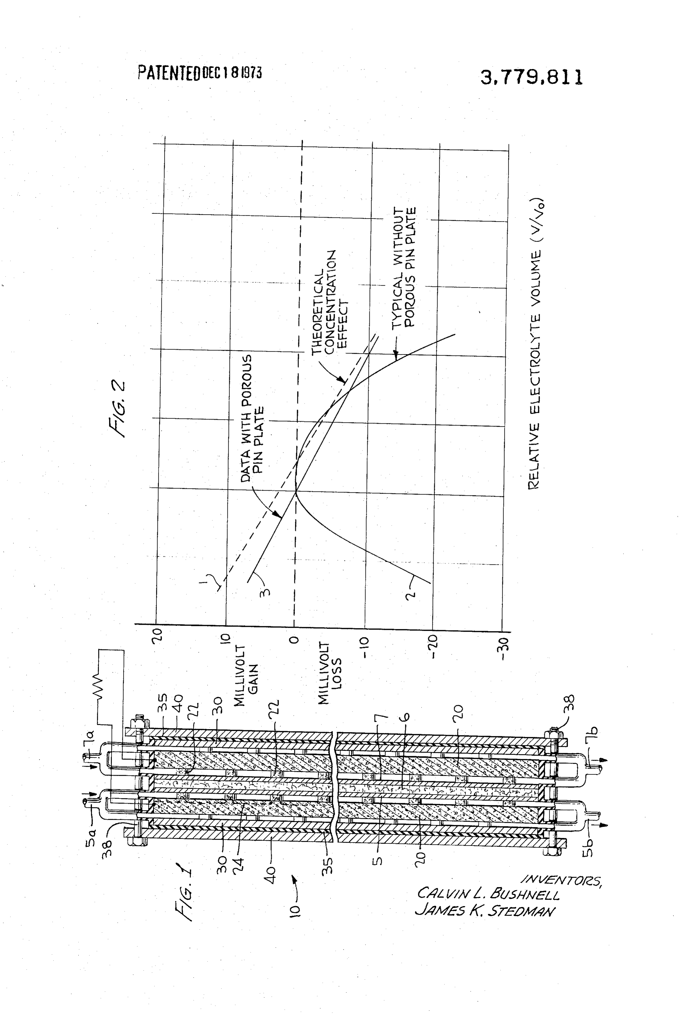
use of the porous pin plates. This is shown graphically in FIG. 2 of the drawing. From the graph it is seen that
In order to more specifically demonstrate the present the electrochemical output of the presently disclosed invention, reference is made to the accompanying cell is substantially identical to the output which is the drawing wherein O oretically obtainable with a matrix-type cell. Note lines FIG. 1 is a transverse sectional view through a single 1 and 3. In contradistinction, without the porous pin fuel cell constructed in accordance with the present in plate, the current characteristics of a matrix cell are vention; and changed substantially at both low and high electrolyte FIG. 2 is a graph illustrating electrolyte volume toler volumes as a result of the varying electrolyte interface ances of a matrix-type fuel cell. 5 in the electrodes and the varying effective electro Referring to FIG. 1 of the drawing, the fuel cell 10 chemical area of the cell electrodes. Accordingly, the comprises anode 5 and cathode 7 separated by an elec advantages of the present system are readily apparent. trolyte matrix 6. In the embodiment shown, electrodes Although the present invention has been described 5 and 7 are lightweight screen electrodes comprising a with reference to lightweight electrodes comprising a conductive nickel screen embedded in a uniform ad 20 metal support screen embedded in a catalytic mixture mixture of catalytic metal, in this instance platinum, of metal and hydrophobic plastic binder, other elec and polytetrafluoroethylene particles. Th ratio of plati trodes can be employed including non-porous palladi num to polytetrafluoroethylene on a volume basis is um/silver alloy structures as described in U.S. Pat. No. 3:7, with the platinum loading of the electrode being 3,092,517. Furthermore, the so-called Bacon-type 15mg/cm. The electrodes are approximately 10 mils in 25 electrode as defined in U.S. Pat. No. 2,716,670 can thickness. The electrolyte matrix is pressed asbestos also be employed. Although it is indicated that the elec and is approximately 25 mils thick. A porous plate 20 trolyte matrix is made of asbestos, other hydrophilic having a plurality of porous pins 22 is adjacent to and matrices including ceramic materials and polymeric in communication with each of the anode and cathode materials cn be utilized. In addition to nickel, the po through pins 22. In the preferred embodiment shown, 30 rous back-up plate - made by any conventional tech the plate is porous nickel having a total porosity of nique - can be any material which is hydrophilic, i.e., about 80 percent. As apparent from the drawing, each will collect water as a result of capillary action, and in of the porous plates is adjacent to a cooling plate 30. cludes porous copper, tantalum, iron, and the like. As Cooling plates 30 are separated from pressure plates 40 35 a result of availability and over-all characteristics, by insulation 35 and the entire cell assembly held to nickel is preferred. The porosity of the plate can vary gether with threaded tie rods 38. as long as it is sufficiently porous to adsorb water In operation, electrolyte matrix 6 is saturated with a through capillary action, but preferably the plate will 30 percent aqueous potassium hydroxide electrolyte have a porosity of from about 35 to 90 percent. The op through air inlet plug, not shown. Sufficient electrolyte 40 erating temperature of the cell can vary as long as it is is added in order that the electrolyte will pass into po not above the critical temperature of the electrodes rous pins 22 and partially into porous plate 20. A possi and/or electrolyte matrix being employed. Preferably, ble electrolyte interface is shown by dotted line 24 in the operating temperature of matrix-type cells of the plate 20 behind anode 5. A reactant gas, in this in type described herein will range from about 20° to 175° stance hydrogen, is fed to anode 5 through gas inlet 5a, 45 C. In addition to the potassium hydroxide electrolyte with excess gas being removed through outlet 5b. An disclosed hereinbefore, other commonly employed oxidant, in this instance air, is fed to cathode 7 through aqueous electrolytes exemplified by acqueous solution inlet 7a, with excess air and impurities being vented of the alkali hydroxides, alkaline earth hydroxides, and through exit 7b. Depending upon the current charac carbonates, as well as strong acid electrolytes such as teristics and operating conditions of the cell, it may be hydrochloric acid, sulphuric acid, and phosphoric acid desirable to cool the cell by passing a cooling gas, i.e., 50 can be employed. Commonly employed reactants, in air, or a cooling liquid such as ethylene glycol, propy addition to hydrogen and oxygen, can be utilized in the lene glycol, or glycerine between cooling plate 30 and cells of the present invention. As will be apparent, the end plate 40 through a channel, not shown. concept of the present invention can be employed in Although in the embodiment shown in the drawing 55 any of the prior art cells where electrolyte volume con porous plates and cooling plates are shown behind each trol within a matrix-type electrolyte is essential. of the electrodes, it can be desirable in order to con Furthermore, although the present invention is de serve space to only have the porous nickel plate and scribed and illustrated in the drawing with reference to cooling plate behind one of the anode or cathode with a single cell, it should be apparent that in preferred the electrolyte volume in the matrix being controlled 60 constructions a plurality of cells will be stacked to through this single unit. As will be readily apparent, gether; and where cooling is not necessary, the porous again depending upon operating conditions, i.e., where metal plates can have the porous pins or ridges on both the current drain is relatively low and the operating sides and serve electrodes of adjacent cells. This will temperatures of the cell are constant, it may not be increase the compactness of a battery of cells. Alterna necessary to utilize a cooling plate at all. This, as will 65 tively, if cooling is necessary, a single cooling chamber be apparent, will substantially save on the total weight can be positioned between two porous plates, with the of the cell and, further, will provide a more compact cooling chamber servicing the two porous plates which cell. are in contact with electrodes of opposite cells. As will
Page 5
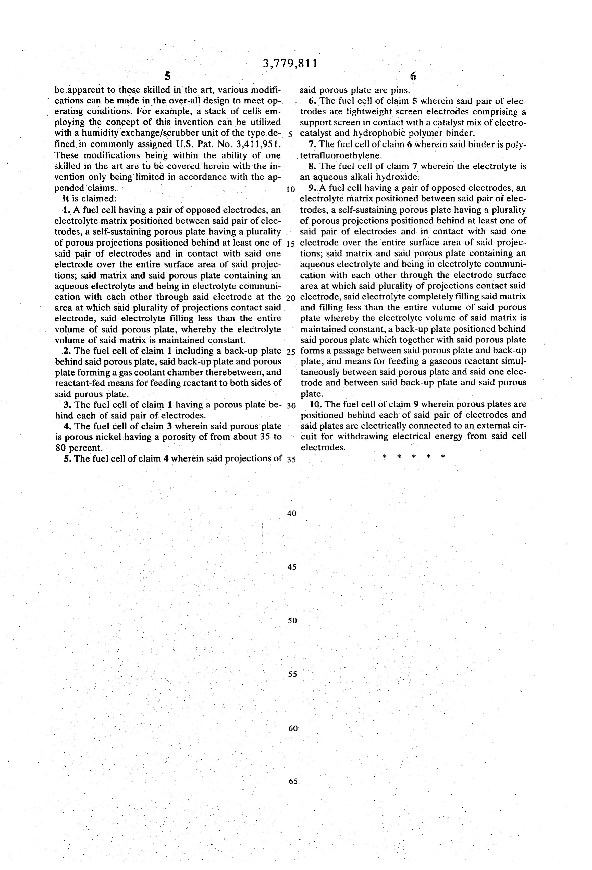
be apparent to those skilled in the art, various modifi said porous plate are pins.
cations can be made in the over-all design to meet op 6. The fuel cell of claim 5 wherein said pair of elec erating conditions. For example, a stack of cells em trodes are lightweight screen electrodes comprising a ploying the concept of this invention can be utilized support screen in contact with a catalyst mix of electro with a humidity exchange/scrubber unit of the type de catalyst and hydrophobic polymer binder. fined in commonly assigned U.S. Pat. No. 3,411,951. 7. The fuel cell of claim 6 wherein said binder is poly These modifications being within the ability of one tetrafluoroethylene.
skilled in the art are to be covered herein with the in 8. The fuel cell of claim 7 wherein the electrolyte is vention only being limited in accordance with the ap an aqueous alkali hydroxide.
pended claims. O 9. A fuel cell having a pair of opposed electrodes, an It is claimed: electrolyte matrix positioned between said pair of elec 1. A fuel cell having a pair of opposed electrodes, an trodes, a self-sustaining porous plate having a plurality electrolyte matrix positioned between said pair of elec of porous projections positioned behind at least one of trodes, a self-sustaining porous plate having a plurality said pair of electrodes and in contact with said one of porous projections positioned behind at least one of 15 electrode over the entire surface area of said projec said pair of electrodes and in contact with said one tions; said matrix and said porous plate containing an electrode over the entire surface area of said projec aqueous electrolyte and being in electrolyte communi tions, said matrix and said porous plate containing an cation with each other through the electrode surface aqueous electrolyte and being in electrolyte communi area at which said plurality of projections contact said cation with each other through said electrode at the electrode, said electrolyte completely filling said matrix area at which said plurality of projections contact said and filling less than the entire volume of said porous electrode, said electrolyte filling less than the entire plate whereby the electrolyte volume of said matrix is volume of said porous plate, whereby the electrolyte maintained constant, a back-up plate positioned behind volume of said matrix is maintained constant. said porous plate which together with said porous plate 2. The fuel cell of claim 1 including a back-up plate 25 forms a passage between said porous plate and back-up behind said porous plate, said back-up plate and porous plate, and means for feeding a gaseous reactant simul plate forming a gas coolant chamber therebetween, and taneously between said porous plate and said one elec reactant-fed means for feeding reactant to both sides of trode and between said back-up plate and said porous said porous plate. plate.
3. The fuel cell of claim 1 having a porous plate be 30 10. The fuel cell of claim 9 wherein porous plates are hind each of said pair of electrodes. positioned behind each of said pair of electrodes and 4. The fuel cell of claim 3 wherein said porous plate said plates are electrically connected to an external cir is porous nickel having a porosity of from about 35 to cuit for withdrawing electrical energy from said cell 80 percent. electrodes.
5. The fuel cell of claim 4 wherein said projections of 35 ; : : -k sk
Provenance
- Collection
- Cited prior art
- Original PDF
- patentimages.storage.googleapis.com →
- Filed
- 1971-03-16
- Pages
- 5
- Method
- pdftotext (the PDF's own text layer) + pdftoppm 300dpi page scans
- Source
- Google Patents bibliographic record
- Granted
- 1973-12-18
- Inventors
- C Bushnell; J Stedman; United Aircraft Corp
- Transcribed from
- patentimages.storage.googleapis.com →