patent · US5346778
Electrochemical load management system for transportation applications
13 September 1994
Page 1 — bibliographic record
United States Patent (19) 11 Patent Number: 5,346,778 Ewan et al. 45) Date of Patent: Sep. 13, 1994 54 ELECTROCHEMICAL LOAD 56) References Cited
MANAGEMENT SYSTEM FOR
TRANSPORTATION APPLICATIONS U.S. PATENT DOCUMENTS
4,988,580 1/1991 Ohsaki et al. ......................... 429/19 75 Inventors: James M. Ewan, Palm Beach
Gardens; Steven M. Misiasxek, Primary Examiner-Kathryn Gorgos
Tequesta; Donald P. Alessi, Jr., Lake Attorney, Agent, or Firm-Paul J. Sutton; Barry G. Park, all of Fla. Magidoff
73) Assignee: Energy Partners, Inc., West Palm A load management system for hydrogen-oxygen fuel Beach, Fla. cells is provided, for powering vehicles. The load man agement system operates such that under normal load conditions air is provided as the oxidizing agent for the (21) Appl. No.: 929,618 hydrogen fuel. At high output conditions the air supply is enriched with additional oxygen. The system com prises means responsive to the amperage output from 22 Filed: Aug. 13, 1992 the fuel cell stack to activate valve means for the addi tion of pure oxygen into the air inlet line. There is also 51) Int. Cl. .............................................. H01M 8/18 provided means for electrolyzing water to produce 52 U.S. C. ........................................ 429/19; 429/17; pure hydrogen and pure oxygen gas, which may be 429/21; 429/24; 429/25; 204/DIG. 4 recyclable to the fuel cell.
58) Field of Search ....................... 429/13, 21, 24, 25, 429/17; 204/DIG. 4, 267; HO1M. 8/02 19 Claims, 4 Drawing Sheets
HYDROGEN STORACE VENTO SAFE LOCATION IN JES5 cA. E. R
VENT
TO SAFE
LOCATION VENTO
SAFE
OCATION
tyre
HIGH
PRESSJRE
TODRAIN
972 VOLACE VCONGWATER
REGLAOR RESERVOR
MOTOR
Page 2
Drawing sheet — no readable text.
Page 3
Drawing sheet — no readable text.
Page 4
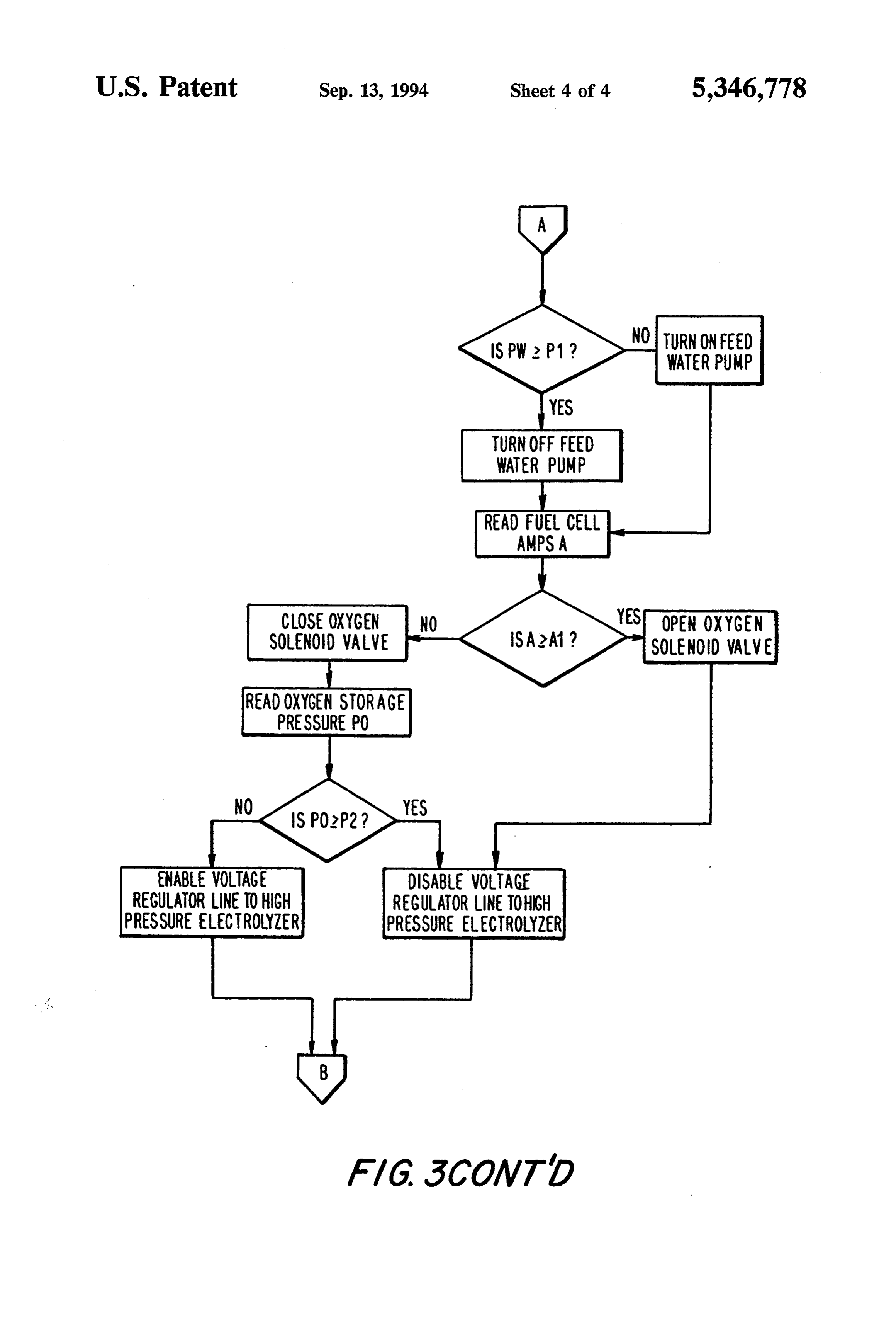
NITATE START
OFFUEL CELL
• TURN ON COOLING SYSTEM WATER PUMP(S)
TURN ON HEAT EXCHANGER FAN(S)
OPEN HYDROGEN SOLENOID WAVE
• CLOSE HYDROGEN PURGE SOLENOD WAVE
• TURN ON AIR COMPRESSOR
RESET & START TIMER
READ ALL SENSOR OUTPUTs
MEASUREMENTS WITHIN FUEL CELL, SHUTDOWN
ACCEPTABLE BOUNDS?
YES
YES OPENHYDROGEN PURGE
SOENOID FORTSEC
READ FEED WATER
PRESSURE PW
Page 5
NO TURNON FEED
WATER PUMP
SOLENOD WAVE SOLENOO VALVE
READ OXYGEN STORACE
PRESSURE PO
ENABLE VOLTAGE DISABLE VOLTAGE
REGULATORLINE TOHCH REGULATOR LINE TOHIGH
PRESSURE ELECTROYZER PRESSURE ELECTROLYZER
Page 6
brane. These catalytic metals also act as the electrodes
ELECTROCHEMICAL LOAD MANAGEMENT for the cell. Bipolar current collectors/separators are SYSTEM FORTRANSPORTATION used to separate adjacent cells and as the means of col APPLICATIONS lecting and transmitting current flow to outside of each cell. These cells are maintained in "stacks' of a plurality
This invention relates generally to an electrochemi of individual power cells in a series, e.g., 20 cells, which cal, or fuel cell system, especially adapted for transpor then generate the total voltage output. As a general tation applications, i.e., land vehicles. More specifically, rule, the voltage generated by a power cell varies in this invention is directed to a low temperature, air versely with the output amperage taken by the load. oxygen/hydrogen fuel cell having means for providing O The fuel cell stacks, which generate water as a by for surges of peak power output, on demand, as when product from the chemical reaction of hydrogen-con acceleration is required. More particularly, this inven taining fuel and an oxygen-containing oxidant, also tion provides for a hydrogen-air fuel cell system which require the use of water for cooling and for maintaining provides for the oxygen-enrichment of the air to the the integrity of the electrolyte membrane. In many fuel cell in response to peak power requirements, as 15 cases, the by-product water is sufficient to maintain the during acceleration. cooling of the system and to provide the needed humidi BACKGROUND OF THE INVENTION fication of the incoming reactant gases to maintain the integrity of the membrane during operation of the fuel
A fuel cell is a galvanic device which operates in cell. Water is carried from the fuel, or hydrogen, side of accordance with similar electrochemical principles as in 20 the membrane, together with the proton, through the conventional storage batteries, i.e., a positive and nega membrane and thus tending to dry the anode side of the tive electrode are separated by an ion-conducting elec membrane, ultimately causing cracking of the mem trolyte adapted to carry current generated by a cata brane if additional water is not provided to compensate lyzed chemical reaction. Unlike the storage battery, for such loss.
however, the fuel cell has a theoretically infinite energy 25 Generally, it is known to pre-humidify the system by output capacity, dependent solely upon the continuous passing the fuel and oxidant gases through humidifica supply of fuel and oxidant to the reaction system. For tion cells within the cell stack, or to externally humidify the traditional hydrogen-oxidant fuel cell, current flow the fuel and oxidant gases. Examples of such systems are is provided by the flow of electrons associated with the shown in commonly owned U.S. Pat. No. 5,047,298, passage of a positive hydrogen ion through an interven 30 and in an earlier U.S. Pat. No. 4,214,969. With internal ing electrolyte medium to the cathode in the oxygen humidification, the fuel and oxidant gases are initially containing chamber of each cell, resulting in the forma passed independently through humidification cells tion of water and the generation of electric current. The within the cell stack. The gases are there saturated, or energy value of the thus generated current, i.e., the almost saturated, with water vapor and then passed, potential energy of the voltage drop, is directly propor 35 also in parallel, through the individual power cells tional to the energy output resulting from the exother within the stack.
mic oxidation reaction of hydrogen and the oxygen (in It has also been previously suggested that in order to the air) to form water. Fuel cells, generally, have one most efficiently use a fuel cell stack for vehicular pro common limitation: the voltage output of a cell de pulsion, the stack should be, preferably, sized so as to creases with increasing current flow, or amperage, i.e., provide sufficient power, at a useful voltage, for normal as the power being drawn from the cell increases. continuing operation, or cruising operation, when uti In the past, there have generally been three distinct lizing air as the oxidant, and that during peak loads, types of hydrogen-oxygen fuel cells which are capable pure oxygen should be substituted for air as the oxidant. of operating at temperatures below about 500 F.: the This allows the fuel cell stack to be sized for normal low solid polymer proton exchange membrane fuel cell; the 45 power/air operation, but also to provide a peak power alkaline fuel cell; and the phosphoric acid fuel cell. capacity, at a suitable voltage, significantly greater than Each of these types are generally well known and fur for normal operation, and without any complex changes ther description is not needed for this invention. In to the system. Such a system is shown in U.S. Pat. No. general, however, it is the solid polymer proton ex 4,657,829. In this prior patent, the water generated by change membrane fuel cell which will be most effective 50 operation of the fuel cell is electrolyzed during normal in the present invention. In these preferred fuel cells, operation by the excess electrical capacity of the fuel electrical energy is produced by the catalyzed reaction cell. The electrolysis results in the generation of hydro between hydrogen and an oxidizing gas, generally oxy gen and oxygen gases, which in turn are stored under gen, either pure or diluted, as in air. pressure for use when required at peak power capacity. In the first type above, a solid polymeric membrane, 55 Although this system does result in the desired peak capable of passing ions, such as the hydrogen ion, or power availability, the amount of oxygen which must proton, and molecular water, but not the hydrogen or be stored in order to have adequate peak power capac oxygen gases, is used to separate the two gases in anode ity is a problem for a vehicle for which minimum design and cathode chambers, respectively. These membranes weight is desired.
have been formed from, for example, a sulfonated fluo It is thus an object of the present invention to provide rocarbon polymer sold, for example, under the trade a fuel cell power system for a vehicle with improved mark "Nafion' (R) by E.I. Dupont de Nemours, or a peak power capability but with minimized high pressure more recently developed polymer by the Dow Chemi gas storage requirement. It is yet a further object of the cal Corporation. Other suitable materials can be used present invention to provide a fuel cell power system together with this invention, but which do not form a 65 utilizing power created during operation of the vehicle part of this. A noble metal catalyst, for example plati and water generated by operation of the fuel cell to num, in small quantities, is generally embedded in or generate oxygen and hydrogen for use during peak located in direct contact with, the polymeric mem power intervals, but wherein the effectiveness of the
Page 7
oxidant air is enhanced by enrichment with oxygen so output pressurized air from the compressor 7 is option as to reduce the amount of storage capacity required for ally enriched with additional pure oxygen, received peak acceleration requirements. It is yet another and from an, e.g., 500 psig oxygen storage tank 9, for peak further objective of the present invention to provide a power production by the fuel cell stacks. fuel cell powered vehicle having improved efficacy 5 By-product water, from the air side of the pair of fuel during operation. Other objects and advantages will cell stacks 1,2, is carried by the excess air from the become apparent when considering the following spe stacks 1,2 through an initial filter separator 69, from cific description of an example of the invention. which most of the oxygen-lean air, i.e., nitrogen, is
SUMMARY OF THE INVENTION
vented, through a back pressure regulating valve 68;
O and the water is then passed to a cooling water reservoir
The present invention provides a system for power 11, where any remaining air is released and the water is ing a motor vehicle utilizing a fuel cell which operates accumulated, and from which the released gas is on air and hydrogen during constant speed, or cruising, vented.
operation, or during deceleration, and which operates A portion of the high purity water from the cooling on hydrogen and oxygen-enriched air, i.e., up to about 15 water reservoir 11 can be reused for cooling and humid 60% oxygen and preferably not less than about 30%, ifying the fuel cells through a separate water line 77 into and optimally between about 35 and 45% oxygen, when the stacks 1,2, and another portion thereof is passed to a peak power is required, as for acceleration or for mov high pressure pump 13, by which it is pressurized to ing uphill. This invention further provides for the elec preferably, for example, a pressure of greater than about trolysis of water during operation of the vehicle based 500 psig, and then fed into an electrolyzer 15, main upon the power generated during deceleration, or brak tained at the elevated pressure.
ing, of the moving vehicle, and with additional power The gaseous products from the high pressure electro being provided from the fuel cell, as necessary. It has lyzer are at a pressure greater than the pressure in the been found that oxygen-enriched air containing only oxygen storage tank; high pressure oxygen from the 40% oxygen by volume provides sufficient power en 25 electrolyzer can then be passed to the oxygen storage hancement, at the required voltages, when operating at tank 9, without further pressurization or pumping, and the low temperatures, i.e., preferably below about 160 the high pressure hydrogen is fed directly to the cells of F., and the low pressures, i.e., preferably below about 25 the stacks 1,2 to supplement, and to help conserve, the psig, of the present invention. This permits sufficiently stored hydrogen fuel, without regard to whether the high peak power output, while more than doubling the 30 oxygen is also immediately used in the fuel cell stacks. effective storage capacity, based upon peak power out The flow of any excess hydrogen can be buffered by the put time, of pure oxygen without enlarging the storage accumulator 92.
tank. The oxygen storage tank should maintain oxygen The cells in the stacks are electrically connected in at a pressure of at least about 200 psig, and preferably at series, but mass flow through the cells is in parallel. least about 400 psig in order to be able to store sufficient 35 In this preferred embodiment, the electrolyzer 15, is mass of oxygen to feed the fuel cell stacks during ex powered either by a regenerative braking system or by pected peak load periods. excess power output from the fuel cell stacks 1,2, avail
BRIEF DESCRIPTION OF THE DRAWINGS
able during off-peak load periods. It has been deter mined that when the vehicle has a motor with 30 kW of
A further understanding of the present invention can generating capacity, as little as 10 seconds of decelera be obtained by reference to a preferred embodiment set tion from, for example, 45 mph to 25 mph, is sufficient forth in the illustrations of the accompanying drawing. to generate 0.5 standard cubic feet of oxygen. Although the illustrated embodiment is merely exem The electrolyzer 15 comprises a plurality of bipolar plary of systems for carrying out the present invention, cells, which are very similar to those in the fuel cell both the organization and method of operation of the 45 stacks; the cells each comprise anode and cathode invention, in general, together with further objectives chambers separated by an ion-exchange membrane hav and advantages thereof, may be more easily understood ing catalytic electrodes in intimate contact with the by reference to the drawings and the following descrip membrane. The membrane can be formed from a Na tion. The drawing is not intended to limit the scope of fion (R) polymer or another sulfonated fluorocarbon or this invention, which is set forth with particularity in 50 other suitable material, as described above for the fuel the claims as appended or as subsequently amended, but cell stacks.
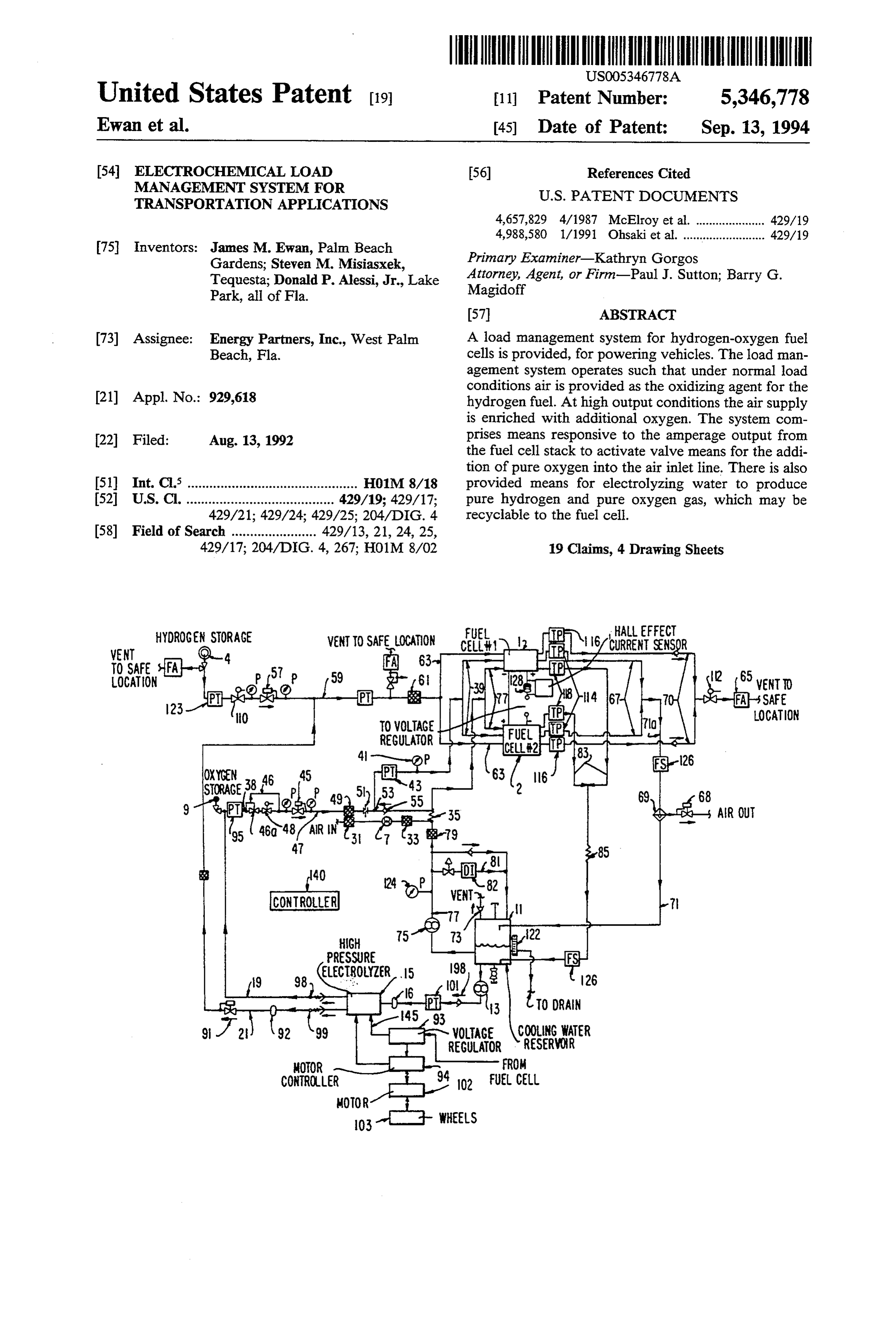
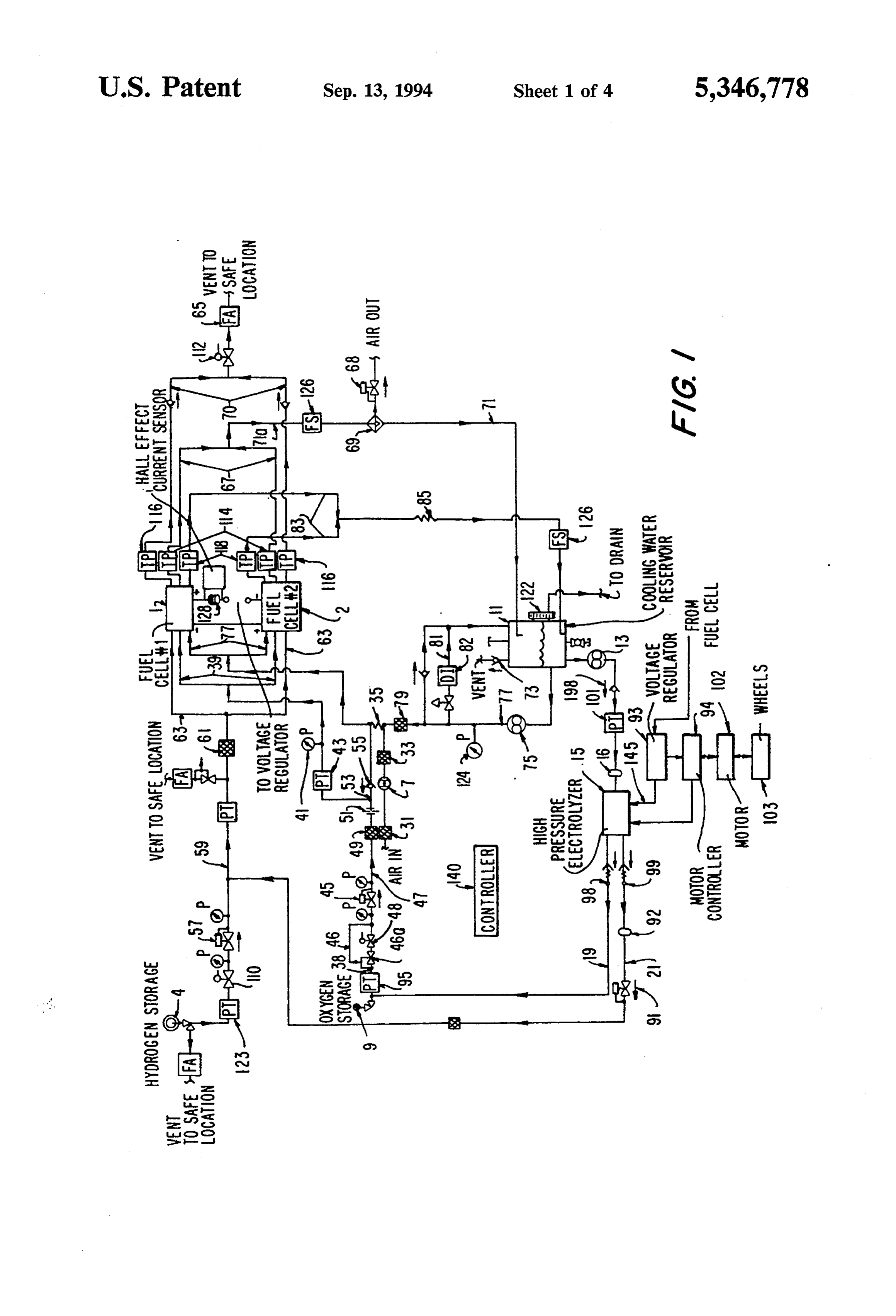
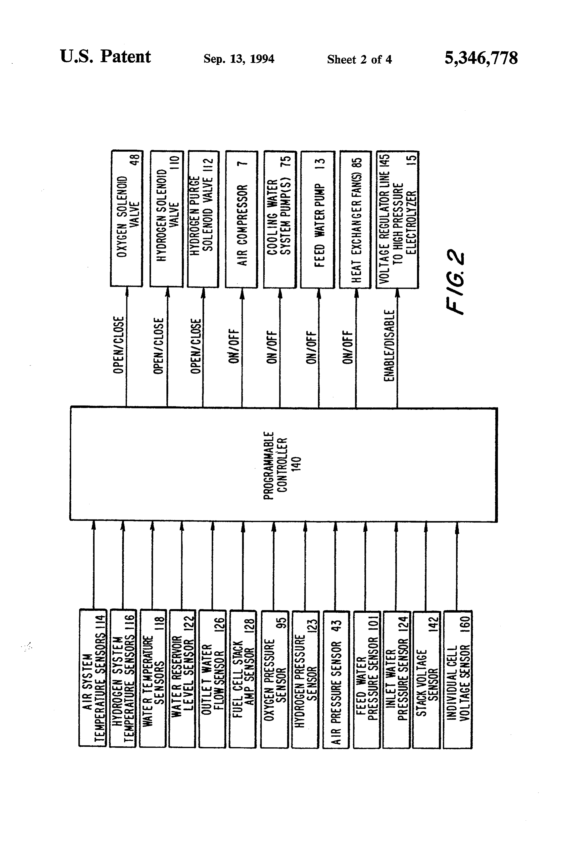
merely to clarify and exemplify the invention. Referring The cathode chambers of the electrolysis cells re to the drawing: ceive water from the pump 13 at approximately 500 FIG. 1 is an overall schematic diagram of a preferred psig, after passing through an accumulator 16 and being system in accordance with the present invention. 55 measured by a pressure transducer 101. The hydrogen FIG. 2 is a diagrammatic function chart for the elec and oxygen gases generated in the anode and cathode tronic programmable controller for the fuel cell power chambers of the electrolyzer, respectively, are then fed system for a land vehicle of the present invention; and into the fuel cell system. The oxygen, passing through a FIG. 3 is a top level logic flow diagram for the opera pressure line 19 at a pressure greater than, e.g., 500 psig, tion of the programmable controller of FIG. 2. passes into the oxygen storage tank 9. The hydrogen
DETAILED DESCRIPTION OF THE
from the anode, exiting through line 21, also at pressures
INVENTION
greater than, e.g., 500 psig, pass into the hydrogen Sys tem and is immediately directed into the fuel cell, to
Referring to the preferred system design shown sche supplement the hydrogen from the storage vessel 4; any matically in FIG. 1, a pair of fuel cell stacks 1,2 receive 65 slight variations in flow requirements are buffered by hydrogen fuel at a desired pressure from a pressurized the volume in the hydrogen accumulator 92. Any excess hydrogen gas storage tank 4 and receive pressurized air water, which is pumped ionically across the membrane from a pressure pump, or centrifugal compressor 7. The with the hydrogen ions, is separated from the gases and
Page 8
preferably discharged. A pressure relief by-pass valve cathode side of the fuel cell stacks 1,2 via the inlet lines 46 is provided in the flow line from the oxygen storage 39 as previously described.
tank 9 to the fuel cell, to automatically by-pass the Hydrogen is provided from a pressurized storage closed solenoid valve 48 when the pressurized oxygen bottle 4, the flow and pressure being adjusted by the storage vessel 9 and line 38 reaches a predetermined pressure regulating valve 57, and into the hydrogen pressure above the desired storage level, e.g., 600 psig, manifold line 59; after passing through a hydrogen filter to permit the excess electrolyzer oxygen to be admixed 61, the hydrogen gas at the desired pressure passes into with air and fed directly to the fuel cells. the anode side of the fuel cell stacks 1,2 through the As pointed out above, the present invention provides twin feedlines 63. Although under optimal conditions a fuel cell power system for powering a vehicle, 10 all hydrogen passing into the fuel cell stack through the whether an automobile, a truck or a train, where the feedlines 63 is converted to water in the stacks 1,2, any power is provided by a relatively low pressure, low small amount of contaminants concentrated in the re temperature fuel cell stack which can use air, or oxy maining hydrogen can at intervals, be flushed out gen-enriched air for peak power periods, as the oxidiz 15 through outlet lines 70 and a flash arrester 65. ing agent, for a fuel which is preferably hydrogen gas. The by-product water, formed in the fuel cells in the The fuel cell stack of the present invention is designed stacks 1,2 by the oxidation of hydrogen to water, is to operate at a temperature of anywhere from above the removed from the cells together with the oxygen-lean freezing point, e.g., above 35 degrees F., to below the air through the air effluent lines 67. The water is passed boiling point of water, preferably not greater than about through a filter separator 69 in the exit manifold 71a, 150 degrees F., and most preferably at a temperature of 20 from which most of the air is vented through a suitable between about 75 degrees F. and 140 degrees F., but back pressure regulating vent valve 68, which maintains optimally below about 130 degrees F. The pressure in the pressure in the system at the desired value; the re maining water, with some remaining air, is drained from the fuel cell stack is at least about 10 psig, preferably at the separator 69 through piping 71 and into the cooling least about 15 psig and not greater than about 30 psig at the exit from the stack, and most preferably not greater 25 water exhaust reservoir 11; the remaining air is permitted to from the reservoir 11, through the pre-set check than about 20 psig. Optimally, the stack operates such valved vent that the pressure at the exit from the air side of each stream vent 73, which works in concert with the up valve 68 to maintain the pressure in the stack is in the range of between about 15 and 20 psig. It is expected that the pressure drop through the stack on reservoir 11 and in the air flow system. During normal operation of the fuel cell stacks 1,2, the air side is approximately not greater than about 1.5 water psi and usually preferably not greater than about 1 psi. 75 at from the reservoir 11 is pumped by a water pump To achieve the low pressure drop and to attain suffi through the fuel sufficient a pressure cell stacks to provide adequate flow 1,2. The water is passed cient gas through-put and thus power output, the cell through line 77 from the pump should be sized such that the linear gas velocity entering 35 filter 79. In addition to filtration,75 and then through a the two sides of each fuel cell is preferably not greater necessary to further deionize the wateratviaintervals, it may, the
shunt than about 100 ft. per second. The mass flow of the circuit 81, which includes a conventional deionizer 82. gases through the system is of course dependent upon The filtered water can then be used to indirectly cool the power required to be generated and the maximum the compressed air in heat exchanger 35 and is then mass flow through the stacks is dependant upon the 40 passed to the humidifier cells in the stacks 1,2 and, number of power cells. For example, a normal mass where desired, also to the cooling sections of the fuel flow for air is in the range of from about 2.0 to about 3.0 cell stacks 1,2.
lb per minute and the mass flow for hydrogen is in the The humidification of the two gases, i.e. hydrogen range of from about 0.04 to about 0.05 lb per minute to and air (or oxygen) in the fuel cell stacks is a feature obtain a current output of 170 amps at 120 volts DC, 45 known to the art (see commonly owned U.S. Pat. No. from the two stacks, each containing eighty-six power 5,047,298), and is not a feature of the present invention. cells. It is sufficient to note that the humidification sections in In this system of FIG. 1, the air passes through an each fuel cell stack are intended to insure against the initial filter 31 and then is pressurized by air compressor drying out of the electrolyte membrane in the power 7 substantially to the desired pressure for feeding into 50 cells. The water from the cooling and humidification the fuel cell stacks 1,2. The pressurized air from the sections of the stacks 12, is then recycled back to the compressor 7 is then refiltered in filter 33 and cooled in water reservoir 11 via lines 83, where it is admixed with heat exchanger 35, indirectly, by water and then passes new by-product water from the power cells in the through a check valve 55 and into the fuel cell stacks 1,2 stacks 1,2. Additional air/water cooling heat exchang through line 39. It is understood that the heat exchanger 55 ers 85 can be provided in line 83 where desired to fur 35 may not be necessary for certain conditions. A read ther cool the water, using air fans, not shown. able pressure gauge 41 and pressure transducer 43 are During the normal operation of the fuel cell, where provided in line 39 for monitoring and safety purposes. the full power output of the normal hydrogen/air fuel When oxygen enrichment of the air is required for cells is not required for propulsion of the vehicle, or, as peak power demand from the fuel cell stacks 1,2, the 60 further explained below, during deceleration of the oxygen solenoid valve 48 is opened and the preadjusted, vehicle, a portion of the water from the reservoir 11 can self regulating pressure regulating valve 45 provides the be passed through the high pressure pump 13, which desired pressure and flow through line 47 and filter 49; pressurizes the water up to greater than the electrolyzer the oxygen passes through the flow controlling orifice pressure, which about equals the storage pressure of the 51 to admix, at juncture 53, with the pressurized air 65 oxygen gas, e.g., usually about 500 psig; the pressurized passing through the check valve 55. The oxygen water is then allowed to flow into the high pressure enriched air containing, e.g., 40% O2 by volume, then electrolyzer stack 15. The water is introduced into the passes through the pressure transducer 43 and into the cathode chambers of the electrolyzer stack 15. The
Page 9
electrolyzer stack 15 comprises a plurality of electro to the art and is not a feature of the present invention. lyzer cells; each cell is divided into a cathode and an Examples of suitable electrical systems utilizing regen anode chamber by an ion exchange membrane having erative braking to supply power to recharge an electri opposed catalytic electrodes, as described above for the cal source are shown, for example, in U.S. Pat. Nos. fuel cell. Bipolar current collectors are positioned to 5,064,013, 4,951,769, and 4,908,553. Although these separate the anode and cathode chambers of adjacent systems do not include an electrolyzer, the connection cells within the stack, also similar to the full cell stacks for providing direct current to the electrolyzer 15 can 1,2; the electrical power for the high pressure electro readily be made in the same manner as for charging a lyzer 15 is connected through a voltage regulator 93, to storage battery, or other direct current load, as shown, the power output electrodes of the fuel cell stacks, or O as a preferred example, by the electric motor generator through a control system 94 to a generator-motor, pow system described in U.S. Pat. No. 4,951,769. As shown ered by, e.g., a regenerative braking system. in that patent, the motor can be operated as a generator The oxygen generated in the cathode chambers of the during regenerative braking; alternatively, but less pre electrolyzer stack 15, and the hydrogen transported to ferred, a separate generator can be provided. the anode sections of the electrolyzer stack 15, are then 15 Overall control over the fuel cell power system is passed to their respective storage tanks 9,4; the oxygen maintained preferably by a programmable controller passes through line 19 to the oxygen storage tank 9, or 140. The controller 140 receives input signals from is directly used to enrich the air feed. When the oxygen sensors located at significant locations in the system, storage tank 9 is filled to capacity, as measured by the and by integrating the information provided by the pressure transducer 95, the oxygen can by-pass the various signals, can control the operating functions of closed solenoid valve 48 when the pre-set, self-regulat the system. Referring to FIG. 2, the programmable ing pressure relief valve 46a opens the by-pass line 46. controller receives input signals from the temperature This results in more efficient operation of the fuel cell probes 114, 116 and 118 located in the exit lines from the stacks. air and hydrogen sides and the cooling water system of The hydrogen gas from the electrolyzer 15 is prefera 25 the fuel cell stacks 1,2. In the cooling and by-product bly passed through the line 21 to the hydrogen feedline water System, the controller 140 also monitors the 59, to be directly and immediately used in the fuel cell water level in the reservoir 11, by sensor 122 and the stacks 1,2, so as to conserve the hydrogen in the hydro water flow rate from the stacks, by flow sensor 126. gen storage unit 4. The high pressure hydrogen from The oxygen and hydrogen gas storage pressures are the electrolyzer, e.g. at about 500 psig, is passed 30 measured by the pressure transducers 95,123 respec through an accumulator 92 (which also permits removal tively, and the air feed pressure into the stacks is mea of excess water) and then passes through a pressure sured by the transducer 43 in the manifold line 39. The regulating valve 91, through which the pressure is cooling and humidification water inlet pressure into the dropped to slightly above that for the hydrogen passing stacks is measured by the pressure gauge 124. from the storage pressure regulating valve 57; this per 35 The electrical output from the stacks is measured by mits the electrolysis hydrogen to be preferentially used the fuel cell stack amp sensor 128 and an overall stack in the fuel cell stacks 1,2, in the place of the hydrogen in voltage sensor, not shown; there is also provided an the storage tank 4. individual cell voltage sensor for each power cell in the The pressure of the gases and the liquids in the fuel stacks 1,2, also not shown in FIG. 1. cell stacks should be maintained at the desired relatively The system shown in FIG. 1 is controlled by the low levels throughout the operating cycle of the fuel programmable controller 140 programmed in accor cells. The pre-set pressure regulating exhaust valves dance with the top level logic flow diagram of FIG. 3. 68,73 in the air system, together with the controls in the As shown by the logic diagram, initiating startup of the inlet lines to the fuel cell stacks cooperate to maintain system results in signals being sent to open the hydro the desired pressures. 45 gen solenoid valve 110, and to turn on the cooling sys Similarly, the low temperatures desired for operating tem water pump 75, the heat exchanger fans 85, and the the fuel cell stacks are maintained by the cooling water air compressor 7. Once started up, the controller signals flow as well as by controlling the inlet temperatures of to open or close the oxygen solenoid valve 48, to enrich the fuel and oxidant gases, e.g., hydrogen and air, or the air flow to the stacks; to open and close the hydro oxygen-enriched air. The desired high pressure in the 50 gen purge solenoid valve 112, at predefined intervals, to electrolyzer can be maintained during the periods of prevent the buildup of impurities in the hydrogen side time that it is not powered, by the pre-set, spring-loaded of the stacks 1,2; and to close down the entire system if flow control valves 98.99 located, respectively, in the the various sensor measurements are outside of pre oxygen and hydrogen outlet lines 19,21 from the elec determined bounds, such as excessive temperatures or trolyzer 15, and the check valve 198 located upstream 55 pressures in the stacks.
of the electrolyzer 15. These flow control valves 98.99 The programmable controller 140 also controls the are held closed by their springs until such time as the operation of the electrolyzer 15 and its interaction with pressure differential across each valve is sufficient to the fuel cell stacks and its supply system. The electro overcome the spring force, e.g., about 20 psi. lyzer 15 provides oxygen gas to refill the oxygen stor The structures of the fuel cells, the humidification 60 age unit during cruising or, when the storage unit is full, cells in the stacks 1,2 and the structures of the electroly to improve efficiency of fuel cell stack operation during sis cells in the electrolyzer 15 are not in detail a part of deceleration, and concurrently to provide additional this invention. Examples of suitable such cells are hydrogen gas feed to the stacks 1,2 during that period. shown, for example, in U.S. Pat. Nos. 4,214,969, The electrical power output from the stacks 1,2 is all 4,210,512, 3,432,355, 3,392,058, 3,297,484 and 3,134,697. 65 sent to the voltage regulator 93, fron which it is distrib The regenerative braking power supply system, com uted, at substantially constant voltage, to the electro prising the vehicle wheels 103, the drive motor/genera lyzer 15 and/or to the motor 102, via the motor control tor 102, and the motor controller94, itselfis well known ler 94, for driving the wheels of the vehicle. The volt
Page 10
age regulator 93 is required because of the well-known The switching of the solenoid valve 48 can also be variation in the output voltage from the fuel cell stacks accomplished, for example, by directly, electro 1,2 with change in the output current. The circuit 145 mechanically mechanically, opening the valve as a re from the voltage regulator 93 to the electrolyzer 15 is sult of a signal received, for example, from the accelera preferably closed only when the oxygen storage tank 9 tor control of the vehicle, e.g. an accelerator pedal. requires filling and the vehicle is not accelerating or Consumption of the oxygen from pressure vessel 9 going uphill; at all other times that circuit is open so that ultimately results in the tank pressure falling to below power from the fuel cell stacks 1,2 is not used for elec the minimum level, which again automatically provides trolysis. a signal from pressure transducer 95 to reactivate the The feed water pump 13, for feeding water at high 10 power to the electrolyzer 15 and to the high pressure pressure to the accumulator 16, is controlled directy by pump 13 as soon as the peak power demand on the fuel the programmable controller 140 when the entire sys cell stacks 1,2 is discontinued. Water from the reservoir tem is turned on or off. The pump 13 is turned on or off 11 is then passed into the high pressure electrolyzer 15, in response to a signal from the transducer 101, which and hydrogen and oxygen gases are again produced, measures the pressure in the accumulator 16. The flow 15 until the oxygen pressure in the storage tank 9 is in of water to the electrolyzer 15 is passively controlled by creased to the desired pressure level. the pressure differential between the accumulator 16 and the electrolyzer 15, in parallel with the closing and fuelIt cell is recognized that there is a continuing load on the opening of the power circuits to the electrolyzer, either maintain system, even during idling or deceleration, to through the voltage regulator 93, or the motor control 20 powering of the operations, its own various including for example, the pumps, fans and control ele
A pressure transducer 95, located adjacent the oxy ments; this usage is generally referred to as the "hotel
gen storage tank 9, provides a signal to the controller What is claimed is:
140 when the tank pressure falls below the value when 1. A fuel cell power system for a vehicle comprising the tank is “full'. The controller 140 is programmed to 25 a fuel permit the closing of the circuit between the voltage as fuelcell and stack designed to operate using hydrogen gas air as the oxidant during periods of normal regulator 93 and the electrolyzer 15, but only if the power output, the system comprising the fuel cell stack; voltage sensors 160,142 indicate that the power load on means for providing the fuel cells is not at or above the maximum for opera fuel cell; and air meanshydrogen for under pressure to the supplying pressurized air as tion with air; this permits the use of excess fuel cell 30 an oxidant gas for the fuel cell stack; wherein the im power to operate the electrolyzer 15 until the oxygen storage tank 9 has reached the desired pressure value provement comprises: the fuel cell stack being designed indicating "full'. Similarly, if the oxygen tank 9 is full to operate at a pressure of not more than about 30 psig and there is no power being generated, by the regenera above atmospheric pressure, and at a temperature tive braking system 103,102.94, to the electrolyzer 15, as 35 below the boiling point of water at ambient pressure, signaled by an increase in feed water pressure measured and further comprising elevated pressure oxygen stor by the transducer 101, a signal is sent to shut down the age means to store substantially pure oxygen under feed water pressure pump 13. A pair of check valves elevated pressure; valve means in fluid flow connection 98.99 serve to prevent reverse flow of gases into the between the oxygen storage means and the air means, electrolyzer 15, from the high pressure storage tanks and means responsive to an amperage output from the 49, while maintaining the high pressure in the electro fuel cell stack above a set level, for opening the valve so lyzer 15 in concert with the feed pump 13. It must be as to add pure oxygen to the supply of pressurized air noted that the feed pump 13 acts as a valve when it is fed to the fuel cell stack, to enrich the air fed to the fuel not operating, to seal off the reservoir 11 from the elec cell stack to contain at least 30% but not more than 60% trolyzer 15. Alternatively, the feed pump 13 can be 45 oxygen by volume during periods when the amperage turned on by the controller 140 in response to current output is above a set level.
being drawn by the electrolysis cell stack 15 by the 2. The fuel cell power system of claim 1, further operation of the regenerative braking system. comprising an electrolyzer for electrolyzing water to When the fuel cell amp sensor 128 indicates that the produce hydrogen and oxygen; means to supply an power being drawn by the motor is above the desired 50 electrolysis current to the electrolyzer; and conduit maximum for hydrogen/air operation, the controller means to carry the oxygen from the electrolyzer to the 140 is programmed to enrich the airflow to the fuel cell elevated pressure storage means.
stack by the addition of pure oxygen from storage tank 3. The fuel cell power system of claim 2, wherein the 9: the solenoid valve 48 is opened, causing the pressur vehicle is a land vehicle comprising wheels, and ized oxygen to flow through line 47, to the pressure 55 wherein the means to supply an electrolysis current to regulating valve 45, where the pressure is dropped to the electrolyzer, comprises regenerative braking power slightly above that of the compressed air pressure from means mechanically connected to the wheels of the the heat exchanger 35, and through the flow controlling vehicle and electrically connected to the electrolyzer. orifice 51, to be admixed with the compressed air at 4. The fuel cell power system of claim 3, further junction 53. The flow control orifice 51 is designed to comprising electrical control means electrically con provide the required amount of oxygen to be admixed nected between the fuel cell stack and the electrolyzer with the compressed air to form the desired enrichment and designed to supply current from the fuel cell stack of the air. Such an orifice design for the precise meter when power demand for operating the vehicle is below ing of gas flow is well-known, based upon the quantity a set level.
and pressure drop required for the oxygen. The orifice 65 5. The fuel cell power system of claim 2, comprising can also be variable, as with a needle valve; thus, per a water reservoir in fluid flow connection between the mitting variation in the extent of the enrichment as fuel cell stack and the electrolyzer, and a pressure pump required for the fuel cell stacks. for pressurizing water from the reservoir and feeding
Page 11
the pressurized water to the electrolyzer at a pressure ing air under pressure as an oxidant gas for the fuel cell greater than that in the oxygen storage means. stack; the fuel cell stack is designed to operate at an 6. The fuel cell power system of claim 2, wherein the increased pressure of not more than about 30 psig and at electrolyzer is operated at a pressure of at least about a temperature below the boiling point of water at ambi 200 psig. 5 ent pressure; and an electrolyzer for electrolyzing water 7. The fuel cell power system of claim 2, further to produce hydrogen and oxygen; means to supply an comprising means to feed the hydrogen generated by electrolysis current to the electrolyzer; conduit means the electrolyzer during normal power operation of the to carry the oxygen from the electrolyzer to the ele fuel cell stack directly back to the fuel cell stack. vated pressure storage means; a water reservoir in fluid 8. The fuel cell power system of claim 1, wherein the 10 flow connection between the fuel cell stack and the fuel cell stack is designed to operate at a temperature in electrolyzer; and a pressure pump for pressurizing the range of from about 75° to about 130 F. water from the reservoir and feeding the pressurized 9. The fuel cell power system of claim 8, wherein the water to the electrolizer at a pressure greater than that fuel cell stack is designed to operate at a pressure of in the oxygen storage means.
from about 15 to about 25 psig 15 15. The fuel cell power system of claim 14, wherein 10. The fuel cell power system of claim 1, wherein the the fuel cell stack is designed to operate at a tempera fuel cell stack comprises an air inlet and an air outlet, ture in the range of from about 75 to about 130 F. and and wherein the air passing through the fuel cell stack is at a pressure of from about 15 to about 25 psig, subject to a pressure drop between the inlet and outlet, 16. In a process for galvanically generating electric and wherein the fuel cell stack is designed to operate 20 ity, the process comprising separately passing hydrogen such that at maximum power for air, the pressure drop gas and air through a stack of ion-exchange membrane for air between the inlet to and the outlet from the stack fuel cells, to generate electrical current and by-product is not greater than about 1.5 psi. water, and removing the by-product water; wherein the 11. The fuel cell power system of claim 1, wherein the improvement comprises feeding the air and hydrogen system is so designed that the air feed to the fuel cell 25 gas to the fuel cell stack at a pressure of not greater than stack is enriched to not more than about 50% oxygen by about 30 psig and at a temperature below the ambient volume. boiling point of water, and further providing pure oxy 12. The fuel cell power system of claim 1, wherein air gen gas which is admixed with the air fed to the fuel cell is pressurized in compressor means powered by elec stack so that oxygen enriched air is fed to the fuel cell tricity from the fuel cell stack to a pressure in the range 30 stack when the amperage output from the fuel cell stack of between about 15 and 20 psig, and the pressurized air is above a set level, wherein the proportion of oxygen in from the pump is then cooled before being fed to the the oxygen enriched air is not greater than about 60% fuel cell stack. but not less than about 30% by volume. 13. The fuel cell power system of claim 12, wherein 17. The process of claim 16, further comprising pres the pure oxygen gas admixed with the pressurized air is 35 surizing the by-product water to a pressure of at least initially stored at a pressure of at least about 200 psig about 200 psig, electrolyzing the by-product water to and is expanded upon admixing with the pressurized air. form hydrogen and oxygen gases to be recycled back to 14. The fuel cell power system for a vehicle compris the fuel cell stack.
ing a fuel cell stack which is operated by hydrogen gas 18. The process of claim 17, wherein the electrical fuel and air during normal power intervals and oxygen 40 power for electrolyzing the by-product water is gener enriched air to contain at least 30% but not more than ated at least in part by regenerative braking. 60% oxygen by volume during peak power intervals, a 19. The process of claim 18, wherein at least a portion fuel cell stack having a plurality of cells, each cell com of the power for electrolyzing the by-product water is prising an anode and a cathode separated by an ion-ex provided from the fuel cell stack when operating at change membrane; means for providing hydrogen 45 below set power level.
under pressure to the fuel cell stack; means for supply k k k : k
Provenance
- Collection
- Cited prior art
- Original PDF
- patentimages.storage.googleapis.com →
- Filed
- 1992-08-13
- Pages
- 11
- Method
- pdftotext (the PDF's own text layer) + pdftoppm 300dpi page scans
- Source
- Google Patents bibliographic record
- Granted
- 1994-09-13
- Inventors
- James M. Ewan; Steven M. Misiasxek; Donald P. Alessi, Jr.; Energy Partners Inc
- Transcribed from
- patentimages.storage.googleapis.com →