patent · US5525041
Momemtum transfer pump
11 June 1996
Page 1 — bibliographic record
United States Patent (19 11 Patent Number: 5,525,041 Deak 45) Date of Patent: Jun. 11, 1996 54 MOMEMTUM TRANSFER PUMP 4,398,870 8/1983 Bcntley .................................., 4T/240 4,482,346 11/1984 Rcinickc .. ... 604/152 76 Inventor: David Deak, 420 E. 64 St., New York, 4,687,420 8/1987 Bentley ........ ... 417/240 N.Y. 10021 4,722,201 2/1988 Ilo?ter ct al. ............................., 62/467 4,753,579 6/1988 Murphy ................ . . 47,322
4,808,084 2/1989 Tsubouchi ct al. .. ... iii.323 4,842,493 6/1989 Nilsson ... ... 417/322 (22 Filcd: Jul. 14, 1994 5,020,977 6/1991 lucas ....... ... iii.323 5,174,130 2/1992 lucas ........................................ 62/498 (51 Int. Cl." ....................................... E04B 17700 5,263,341 ll/1993 lucas ........................................ 62/498 (52) U.S. Cl. ............................................ 417163; 417/322 5,270,484 12/1994 Tsuchiya ct al. ......................, 18/653 58) Field of Search ................................ 417/48, 50, 322, FOREIGN PATENT DOCUMENTS 417/572, 63 0447134A2 9/1991 IEuropcan Pat. Of.......... O4 11/02 56 References Cited OTER PUBLICATIONS
l,760,387 5/1930 Wernet ....................................... 4T153 Jan. 2, 1992 with EPA cover page.
2,050,391 8/1936 Spencer ...................................., 230/69 Primary Examiner. Richard A. Bertsch 2,355,618 8/1944 Bodinc, Jr. .................................. 03/1 2,428,460 10/1947 Inglis ........ 03/15 Assistant Examiner. Pctcr G. Korytnyk 2,751,848 6/1956 Smith ........................................ 103/15 57 ABSTRACT 2,842,067 7/1958 Stevens . ... 03/52 2,972,957 2/1961 Fishcr........................................ 103ff6 A pump comprising a chambcr and a transduccr. Thc cham 3,107,630 10/1963 Johnson et al..., ... 103,152 bcr receives a medium to be pumpcd. Thc chambcr has first 3,150,592 9/1964 Stec .......................................... O3/ and sccond cnds and an inlct and an outlct. Thc transducer 3,165,061 1/1965 Smith ct al. ... 03/1 is disposed at the first cind of thc chamber and provides an 3,266,438 8/1966 Savagc ...... 103/255 energy wave within the mcdium which imparts momentum 3,361,067 1/1968 Webb ................... ... 03/ 3,606,583 9/1971 Coughcnour ct al. 417/53 to it wherchy it passes through the outlet by the momentum, 3,743,446 7/1973 Mandroian ........... ... 417/240 4,171,852 10/1979 Hacntjens .................................. 406/85 26 Claims, 10 Drawing Sheets
Arizr.
T2 - - --6
ZayySvywVSNNNNNNNNNYYYY
Page 2
Drawing sheet — no readable text.
Page 3
Drawing sheet — no readable text.
Page 4
Drawing sheet — no readable text.
Page 5
Drawing sheet — no readable text.
Page 6
Drawing sheet — no readable text.
Page 7
Drawing sheet — no readable text.
Page 8
Drawing sheet — no readable text.
Page 9
Drawing sheet — no readable text.
Page 10
Drawing sheet — no readable text.
Page 11
Drawing sheet — no readable text.
Page 12
MOMEMTUM TRANSFER PUMP Furthermorc if thcrc is any altcration of thc chamber design dimensions, then it will result in an opcrational compromisc,
BACKGROUND OF THE INVENTION in addition, since resonant standing wavcs are required for proper operation, and i? these standing waves arc 1. Ficlid of thc Invcntion changed for any reason and bc.comc travcling wavcs, cither This invention relatcs to pumps and pumping action for continuously or discontinuously or by slight variations fluids, which could be liquids, liquid metals, gases or around thc vicinity of the ports duc to phase shifting, then acrosols. It has particular re?crcnce to liquid pumps that thc operation is again compromiscd. would replacc clectromechanical pumps in thc main classi 10 Also where thc wavcs cmittcd from thc diaphragm or fication of compression pumps and force pumps. It is, pic/oclcctric transducer become distoriccd for any reason, if howcvcr, not limitcd thcreto but is broadly applicable to for cxamplc thc wave changcs front a sinusoidal wavc to a pumps for fluids in gencral, irrespectivc of whethcr the fluid complex wavc with harmonics, then thcscharmonics have to is a liquid, a liquid mctal, a gas, or an acrosol medium and bc realizcd as having a recognizable c??icct upon the overall irrespcctive of the character or nature of the installation or 5 c?liciency of the pump's opcration. system in which the pump is cmploycd. There arc frequency limitations conncccd with some of 2. Prior Art thc design features of such pump and that in many instances, The two catcgorics of clectromechanical pumps namely; these limitations as discusscd below could limit thc pump's forcc and compression pumps all requirc moving parts for 20 various applications. In general, if thc frcqucncy chosen is propcropcration and in some special way thcsc parts arc too low, thcn sizc could be a problem, for it is required for designed in relation to thc amount of fluid to be pumpcd per cflicicnt opcration that within thc chamber at lcast onc wavc unit time and furthcr the overall volumc of the physical length be given to the chambcr dimension, Even if a pump design. Compression pumps known as positive dis half-wavclcngth or quarter-wavelength is uscd as a physical placement typcs arc capable of gcncrating great pressure, 25 dimcnsion, thcre arc ccrlain disadvantages to thcsc configu incverthcless requires many moving parts such as a piston, rations relating to cfficiency of opcration. If the frcquency piston rod, crankshaft, and associated valve assemblics. utilizcd is too high, thcn thc fluid could absorb the wave Positive displacement constriction pumps are thc safcst; cncrgy and attenuatic the standing wavcs thus c?l.cc, lug mainly bccause thc pumpcd fluid incver contacts an envi overall opcration. Accordingly this pump design docs not ronment different than its internal tubing. They arc for this 30 providc c?licicnt reliable pump operation undcr all condi fact uscd widcly in the medical and pharmaceutical scctor tions.
where the prevention of contamination is a vital factor. Their Re?crring to thc Lucas patcnts, in both patcnts the thcory major disadvantage lics in thc possible crushing forces upon of opcration and so with thc basic cmbodiment of both thc material being pumpcd if thc tubing constricts com patcnts acknowlcdgcs thc objective of using a gas in thc pletely. The moving parts required thercin wear out from the 35 rcsonant chamber (cavity) and not a liquid, thc latcrof which fatigue caused by continuous opcration. is not achievable,
There is for considcration the operation of prior art The compressors uscd in both Lucas' patcnts likewisc relating to Sonic and ultrasonic pumps that feature as an utilizc cmbodiments which uscs standing wavcs of acoustic cmbodiment using acoustic standing waves for their prin pressure for creating nodes which arc periodic points of ciplc of opcration. Specific references arc to thc patcnts of: 40 minimum pressure and antinodcs which arc pcriodic points Mandroian U.S. Pat. No. 3,743,446, Iucas U.S. Pat. No. of maximum pressurc. The standing wavc phenomcnon of 5,020,977, and Lucas U.S. Pat. No. 5,263,341, course requircs a resonant static for propcr opcration so as Referring to the Mandroian patcnt, it uscs a source of with thcsc compressors of thc Lucas patcnts. sound from a fluctuating diaphragm or piezoelcctric trans These compressors requirc that a very narrow resonant duccr that oscillates at a presclected frequcncy. Thc frc 45 opcrational frequency range bc utilizcd by way of spccial quency of oscillation of thc diaphragm piczoclcctric trans clcctronic control circuitry. This control circuitry includes duccr and the length of thc pump chamber are configured microprocessor controllcd phase locked loops to insure together so that this arrangement forms a resonant cavity frcqucncy stability, thus adding to the complexity of the (chamber) where acoustic standing waves arc cstablished in dcsign. Such control circuitry is inccessary for such a com thc fluid which allows for a pressurc nodc or antinodc at thc 50 plcx compressor system uscd for refrigcration, wall opposite thc diaphragm pic/oclectric transducer. A The csscnsc of Iucas' compressors, require the circation scrics of pressure nodes and antinodes arc distributed along of a standing wave within a resonant chamber or cavity, and thc length of the chambcr, and the number of nodes and further attempting to maintain thc standing wave with its antinodes dcpcnding upon thc length of the chamber and thc ?ixcd periodic nodcs and antinodes of pressure. Thcsc nodes frequcncy of vibration of the diaphragm piczoclcctric trans 55 and antinodes arc requircd to bc preciscly locatcd at thc ducer. cntrancc and cxit fluid ports, for the purposc of moving a Mandroian further describes that thc cntrance port for the gascous refrigcrant onc way into a heat cxchanger, whicre the fluid is locatcd in thc chambcr at onc of pressure nodes and cxcess heat gcncratcd from compression is carricci off and an exit port is located at onc of thc pressurcantinodcs. This thc gascous refrigerant is thcreby cooled to a liquid phasc. cmbodimcnt rcquires that a resonant condition must be 60 This coolcd liquid is then passcd through a volumc that created bc?orc any pumping action occurs and further, it is contains a number of ingrcdicnts to be coolcd-such as food, critical to have thc dimensions of thc chamber such that thc citc. After thchcat of thc food or whatcver, is passed to thc cntrance and cxit ports are preciscly on the nodes and liquid, it (thc liquid) heats up and expands into the gaseous antinodcs for propcroperation. This proper opcration rclics phasconcc more, only then to renter the resonant chamber heavily on frcqucncy resonant conditions within the cham 65 of thc compressor to begin thc cycle all over again. In ordcr bcr; if for any reason there is a frequency shift, then the to accomplish this task, the incrnal mechanism of thc cflicicncy of opcration is decrcascd. compressor requires a longitudinal standing wave and that
Page 13
such wave must be transverse to the exit and entrance ports. ation system losses) after the generation of a traveling wave This mechanism is further established by action of streaming from a transducer or other source of acoustic energy. Further, effecting the overall efficiency of such compressors by this maximum value assigned to the standing wave is taking away energy from the wave. This streaming effect sustained only by the constant acoustic energy injected into occurs when the very same pressure differentials that allow the system through the transducer element. for transverse gaseous flow between exit and entrance ports, 2. A gaseous fluid is the medium of choice for the are of sufficient amplitude to cause a gaseous flow between compressors of Lucas' in order to function properly as a the nodes and antinodes within the resonant chamber. This refrigeration compressor.
results in a continuous forth and back gaseous flow between 3. The actual gaseous fluid flow is transverse to the the nodes and antinodes and sets up a net flow impedance (a 10 acoustic standing wavefront.
complex restriction to fluid flow) to the main flow to the port 4. Precise geometry of the chamber is essential for suc orports. Streaming is similar to hydrodynamic eddy currents cessful operation requiring a resonant mode for the chamber; in fluids or electrical eddy currents in electrical transformers, and additional electronic control measures are required to etc. Decreased efficiency in overall operation is a result of provide frequency compensation circuitry, such as phase such effect. Since the internal mechanism of these compres 5 locked loops that adjusts for frequency drift above and sors is a longitudinal standing wave and that this wave is below the resonant mode of the chamber. transverse to the exit and entrance ports. Accordingly the operation of the compressors is dependent upon the trans 5. The Lucas compressors can utilize a multiplicity of verse or shear wave component of the standing wave. It is acoustic energy sources situated at any one or all of the this transverse component that allows for the initialization of 20 acoustic generated pressure nodes and antinodes, for the the gaseous flow into the exit port by means of a wave purpose of feeding additional energy at these points to gradient from the entrance to the exit ports. increase the overall system efficiency. Another feature of the compressors of Lucas' patents is OBJECTS AND ADVANTAGES the use of one or more ultrasonic drivers which emit periodic ultrasonic energy which may or may not be linear in nature. 25 Several objects and advantages of the invention are: It is stated that the frequency of the transducer is above the to provide a pump with no moving parts which makes use standing wave frequency. It is then asserted that the energy of longitudinal momentum transfer from acoustic is demodulated into pulses of complex waves, and that this radiation pressure exerting a longitudinal force upon is accomplished by the higher frequency components being the molecular structure of the medium (fluid), attenuated by the gaseous environment. What is left then, is 30 to provide an optional ultrasonic transducer arrangement a pulsed complex wave with lower frequency components; using either a single frequency range or a broadband some of which fall into the frequency range of the standing frequency range using a special design configured wave frequency and add energy thereto. transducer,
Additionally, the Lucas patents states that an ultrasonic to provide pumping action not requiring a resonant pump transducer can be used in a non resonant pulsed or modu 35 chamber, thereby eliminating numerous special lated mode. "Non resonant mode' meaning that the fre arrangements inherent with such resonant pump quency, of the transducer is not equal to the frequency of the designs, standing acoustical wave. In this pulsed or non resonant to provide a pump with complete isolation of the medium mode, several items need further clarification: the transducer 40 from the outside environment, operates at its resonant mode and "that' mode is much to provide a pump with one chamber or a multiplicity of higher than the standing wave frequency by design. The chambers for complex pumping arrangements, transducer is switched on and off to create a succession of short pulses; each pulse consists of a short train of high to provide a pump with one transducer or a multiplicity of frequency oscillations. The high frequency components of 45 transducers for complex pumping arrangements, this pulse train are absorbed or attenuated by the gaseous to provide a pump with various frequency selections from medium and the lower frequency components falling within a broadband ultrasonic transducer to accommodate the range of the standing wave frequency will provide the various fluids to be pumped, necessary mode of operation. This is in effect overdrives the to provide a pump usable at high frequencies (i.e. 1 MHz), transducer crystal, creating nonlinear effects and complex 50 to provide an ultrasonic pump without requiring a reso waves leading to Fourier components of many frequencies, nant mode for operation thus eliminating complex some of these being that of the standing wave frequency. control circuitry for basic operation, It is also suggested that a multiplicity of transducers be to provide a method of creating a focused Zone for placed in contact at the nodes and antinodes as such place establishing greater energy densities within the ments would allow energy to be added to the standing wave 55 medium for imparting larger values of momentum to at various points. No doubt energy would be added, more the medium thus enhancing pumping action, over the energy coefficient of transducers is less than unity, and thereby providing with this focused Zone a well the overall effect is like placing a group of transducers in defined volume of the medium which will produce parallel, their energy minus the losses are additive therefore cavitation; which if the cavitation is collected at the the same could be accomplished by using one transducer 60 opposite end of the chamber and if that medium is comparable in energy to all of their additive energies. water, the cavitation will subsequently produce sonolu In view of the above discussion, the following points can minescence and if the output port is modified to prevent be assessed with regard to the devices disclosed by the the flow of fluid, cavitation will collect at this closed Mandroian and Lucas prior art patents: port and the result will be a source of stimulated blue 1. Acoustic standing waves are the primary mode of 65 light energy; making for a blue water laser source. operation of the prior art. Furthermore the standing waves In accordance with the broadest embodiment of the are built up to their maximum value (taking into consider present invention, a pump is provided which comprises a
Page 14
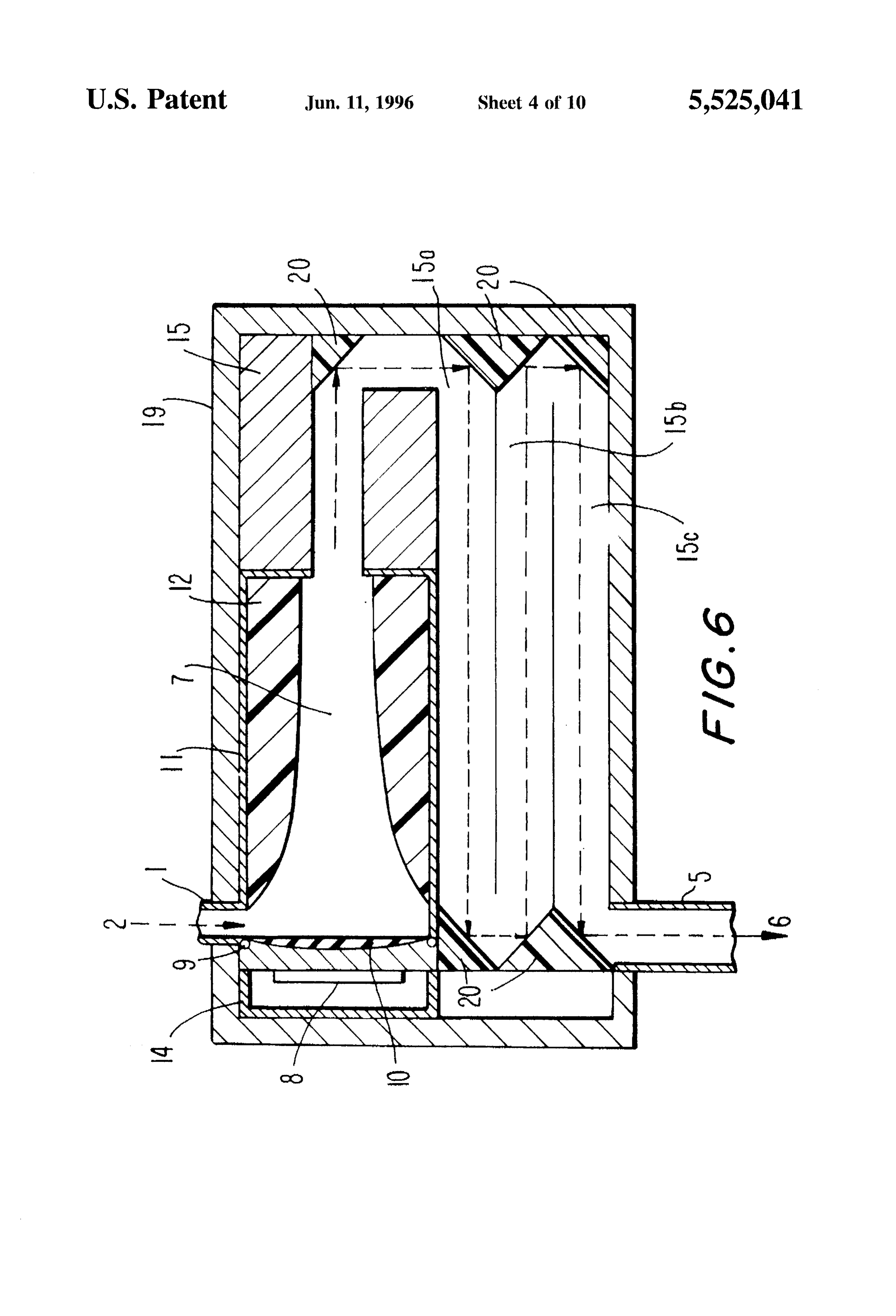
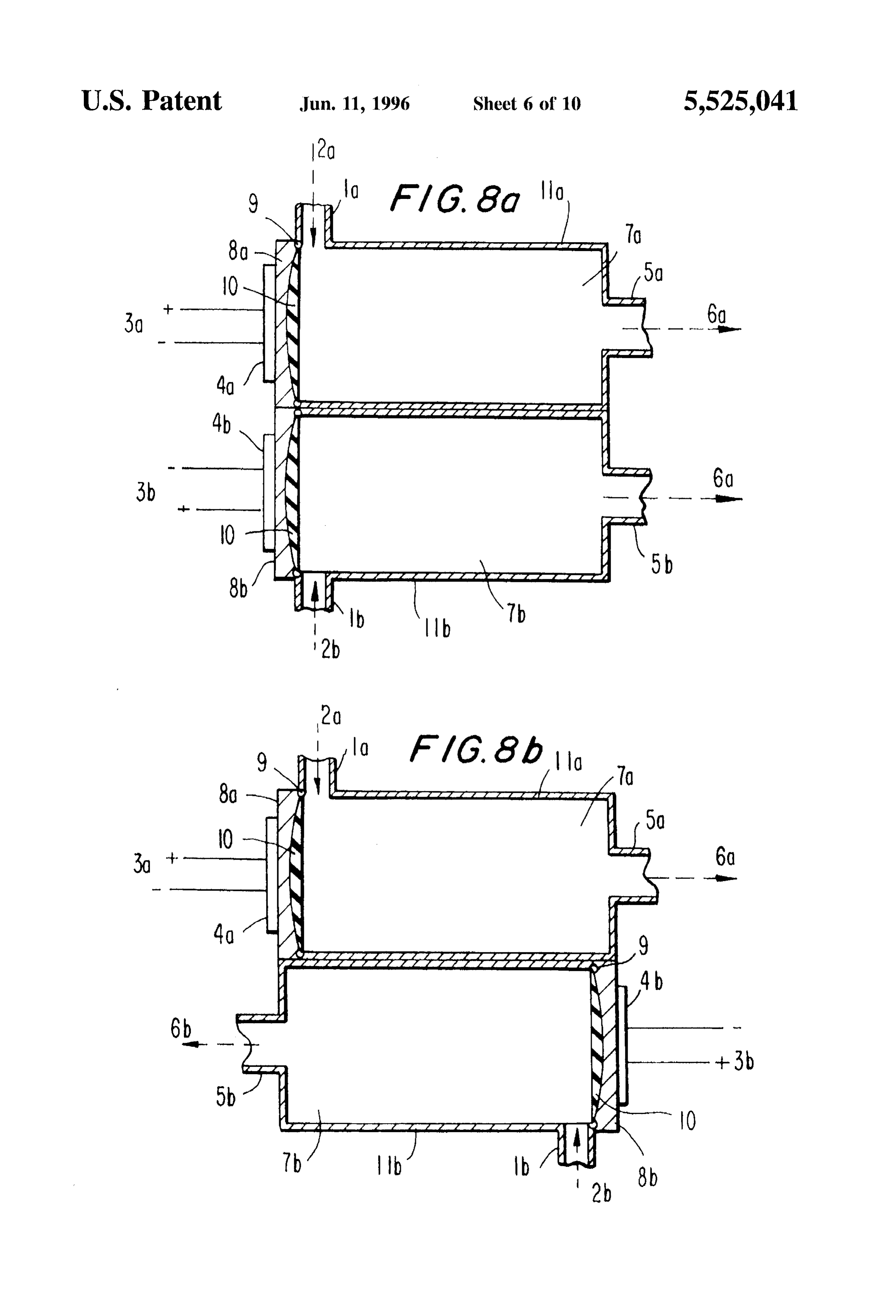
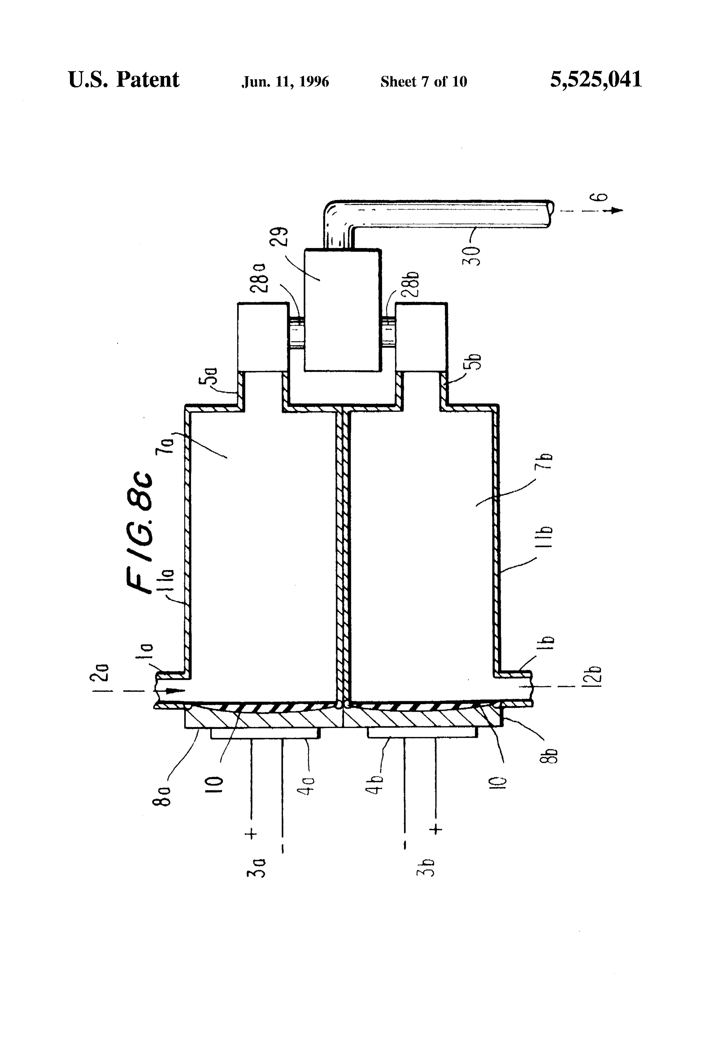
chamber and a transduccr. The chambcr receives a medium transduccr per chambcr; to be uscd in complex pumping to be pumpcd. Thc chamber has first and sccond cinds and an arrangements and oppositic ?low dircctions; inlct and an outlet. The transducer is disposcd at the first cind IFIG. 8c shows in a simplificci scctional side vicw another of thc chambcr and provides an cinergy wave within thc cmbodiment of FIG. 8a with a common mixture tank medium which imparts momentum to it wherchy it passes accessory;
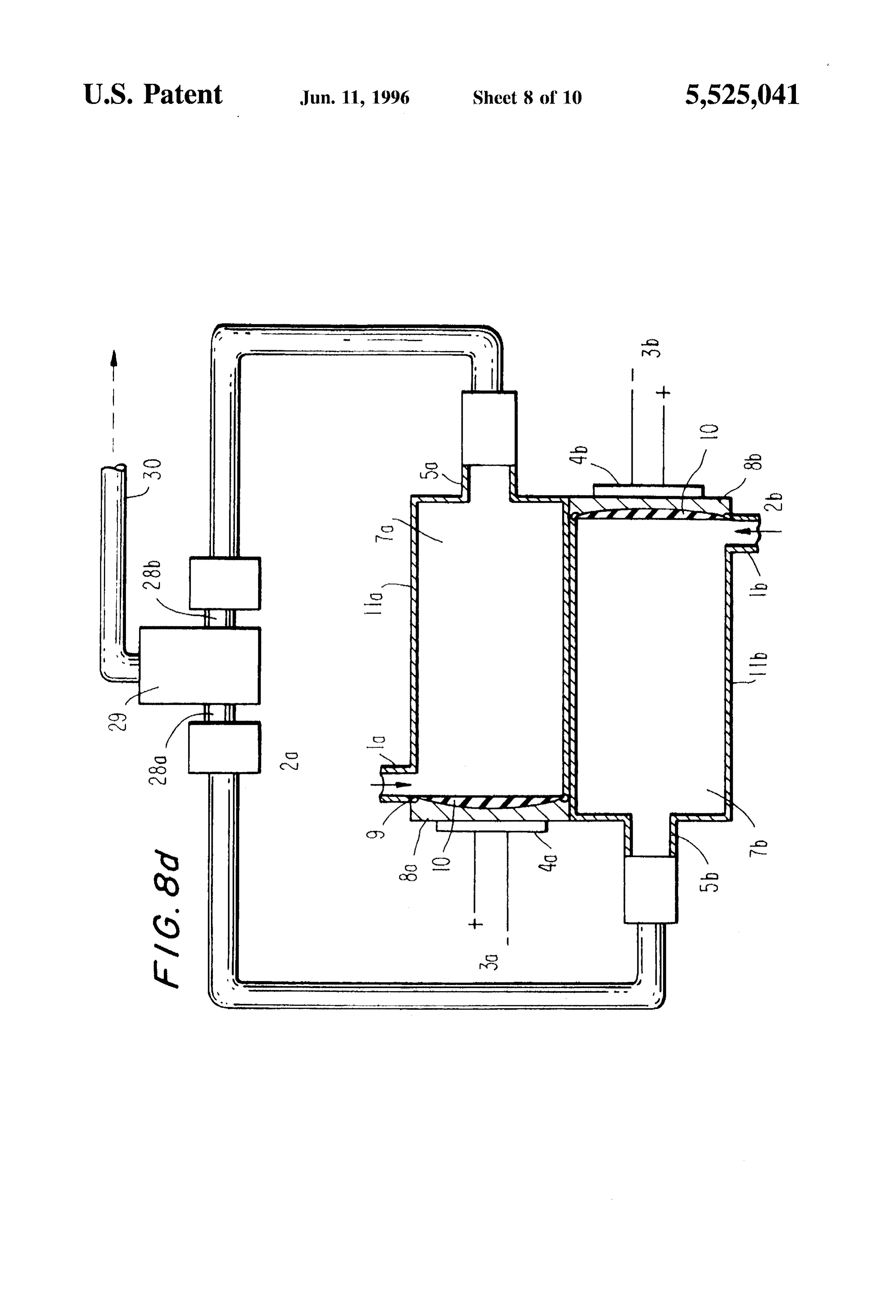
through thc outlet by the momentum. l'IG, 8d shows in a simplifical scctional side vicw anothcr Furthcr objccts and advantages of the invention will cimbodimcnt of l'IG, 8b with a common mixture tank bccome apparent to onc skilled in thc art from a consider accessory;
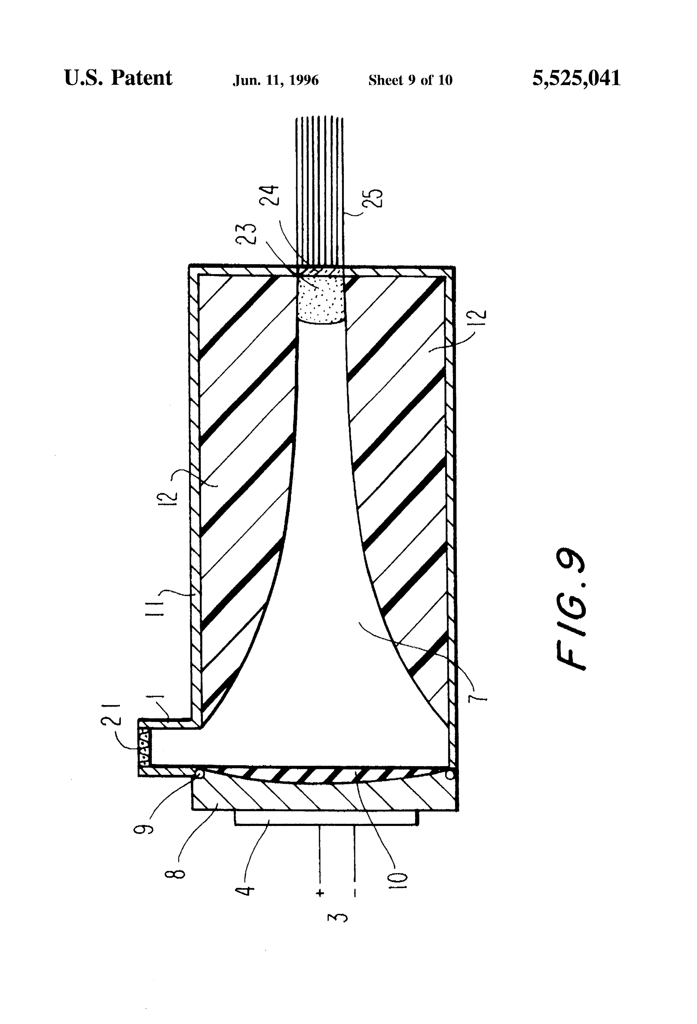
ation of thc drawings and description of the invention. FIG. 9 is another cmbodiment of a pump like devicc
which provides a special bluc water laser source; and
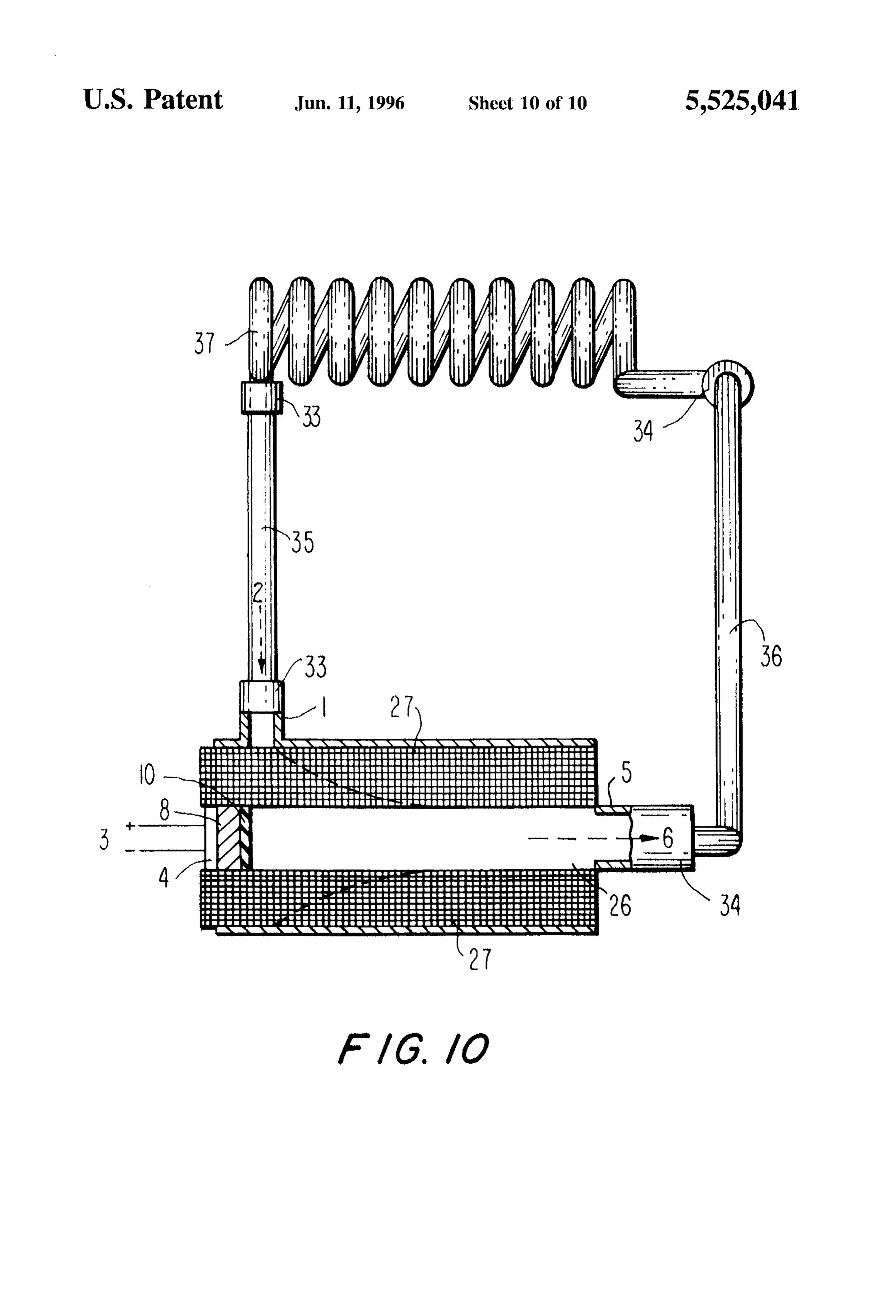
BRIEF DESCRIPTION OF TE DRAWINGS FIG. 10 shows another cmbodiment of thc pump design which uscs ultrasound to gencratic clcctricity;
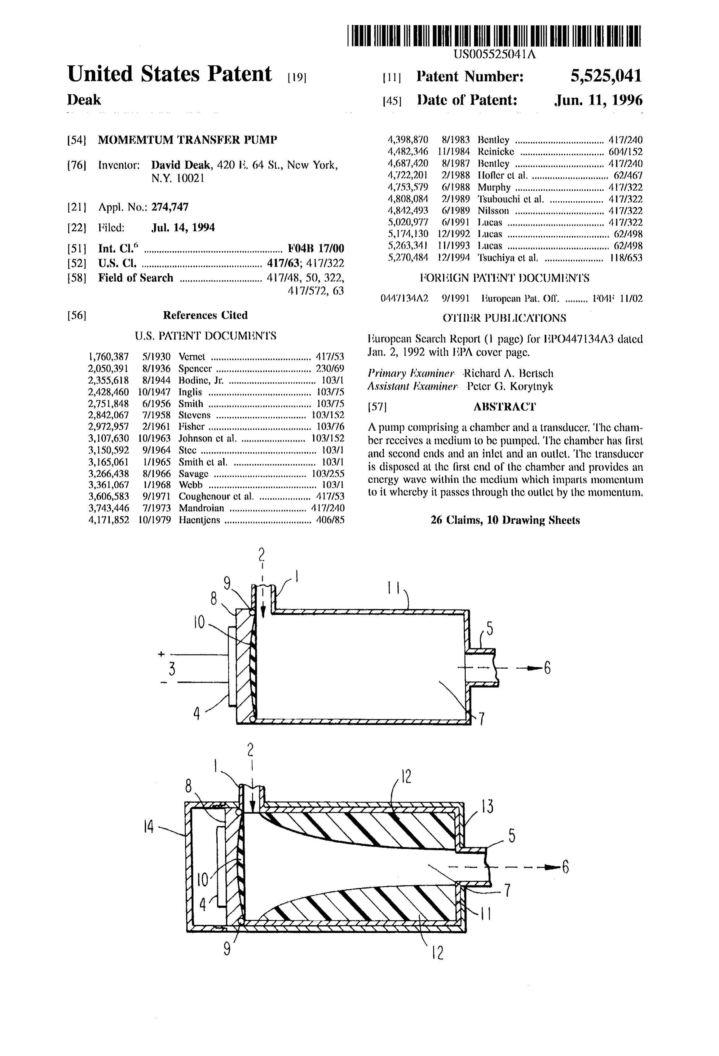
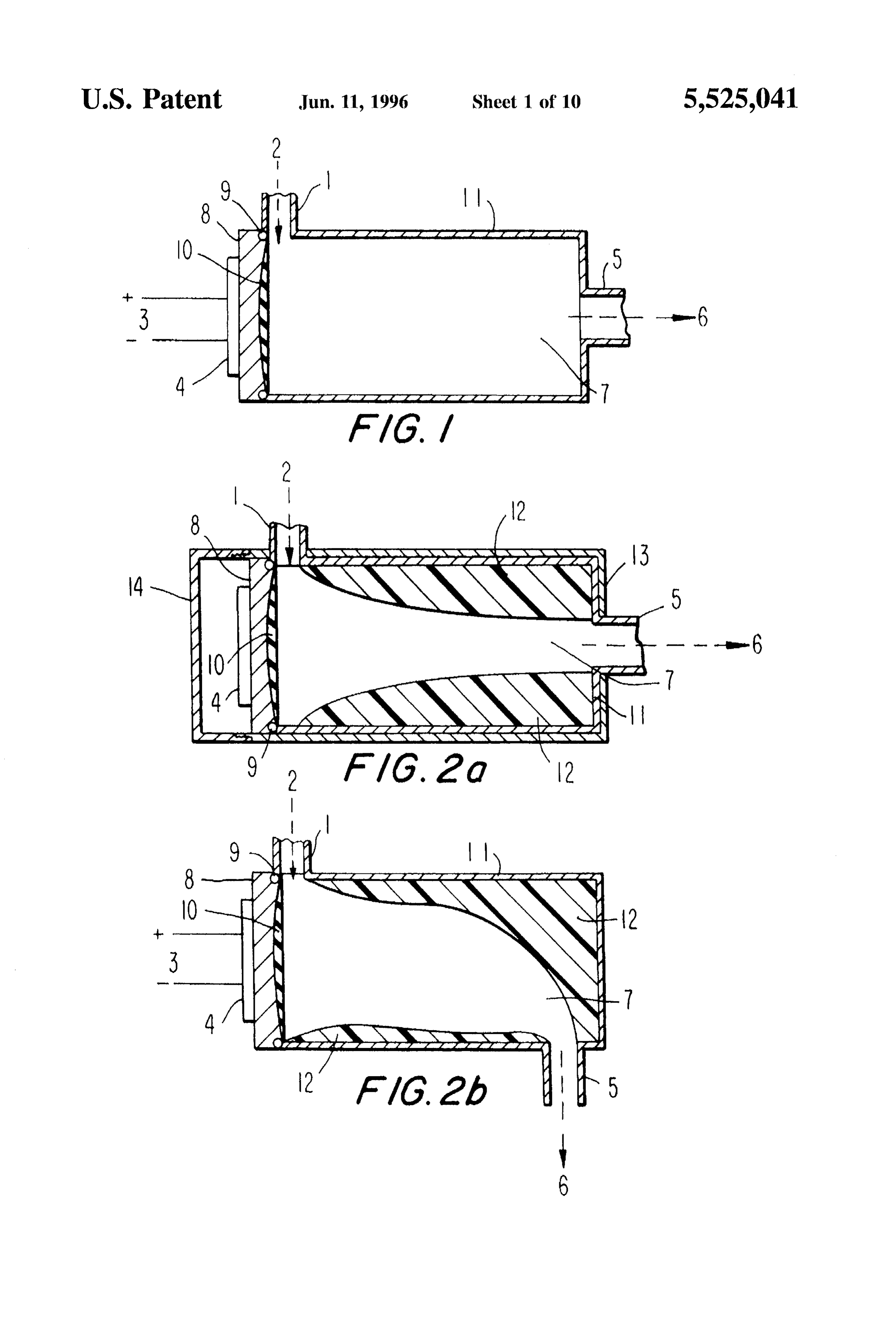
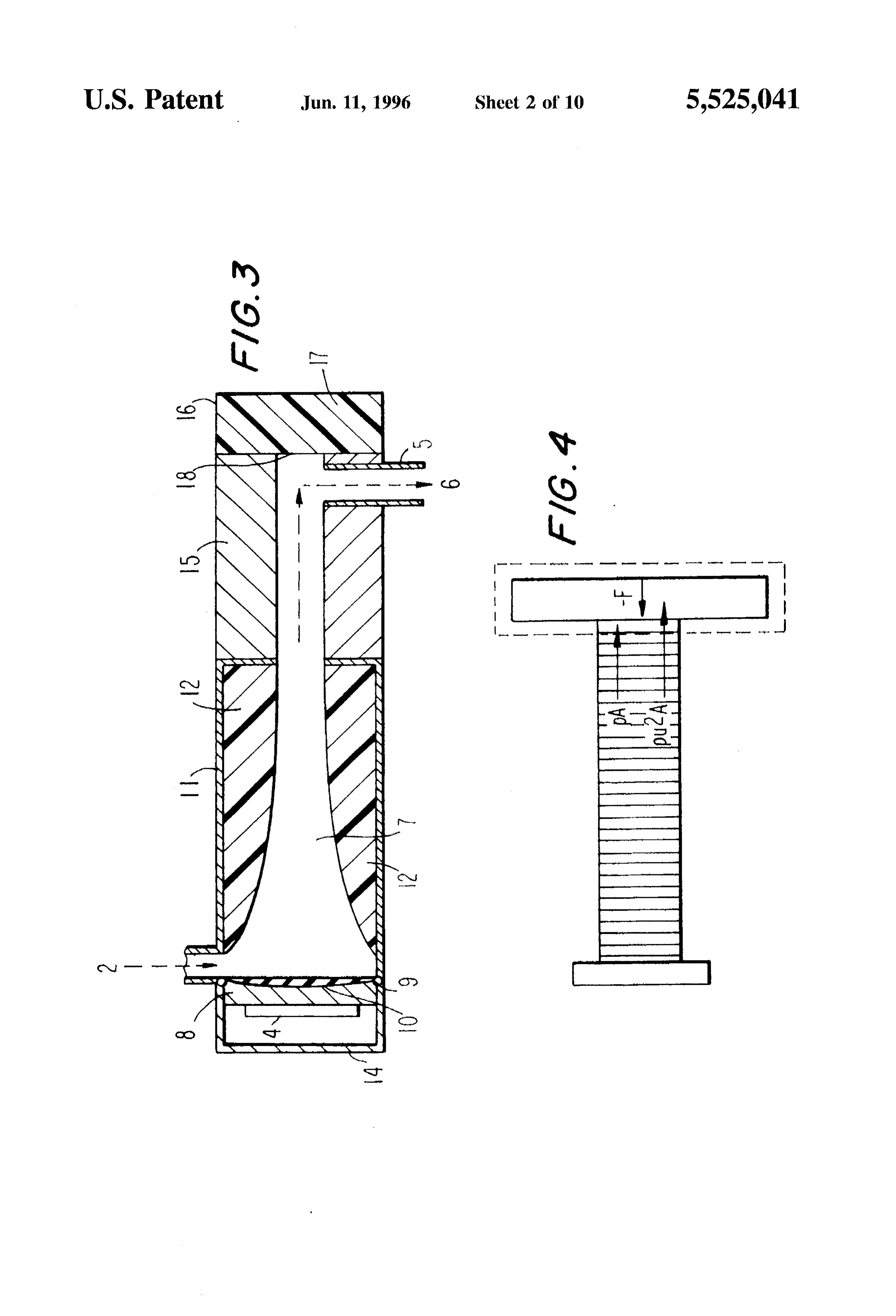
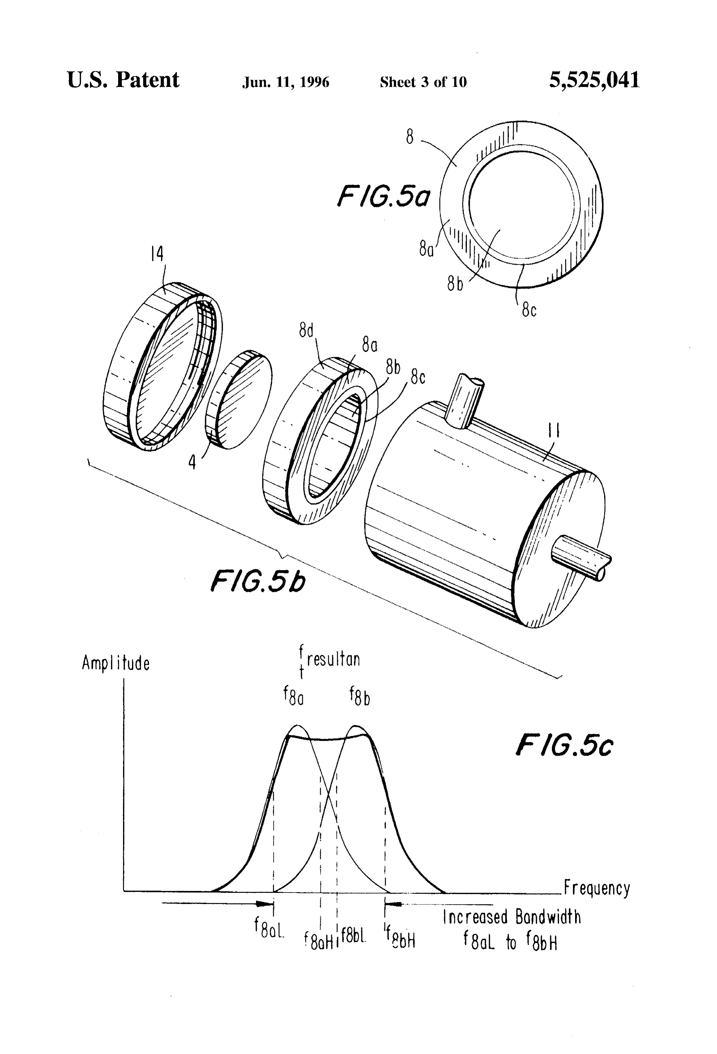
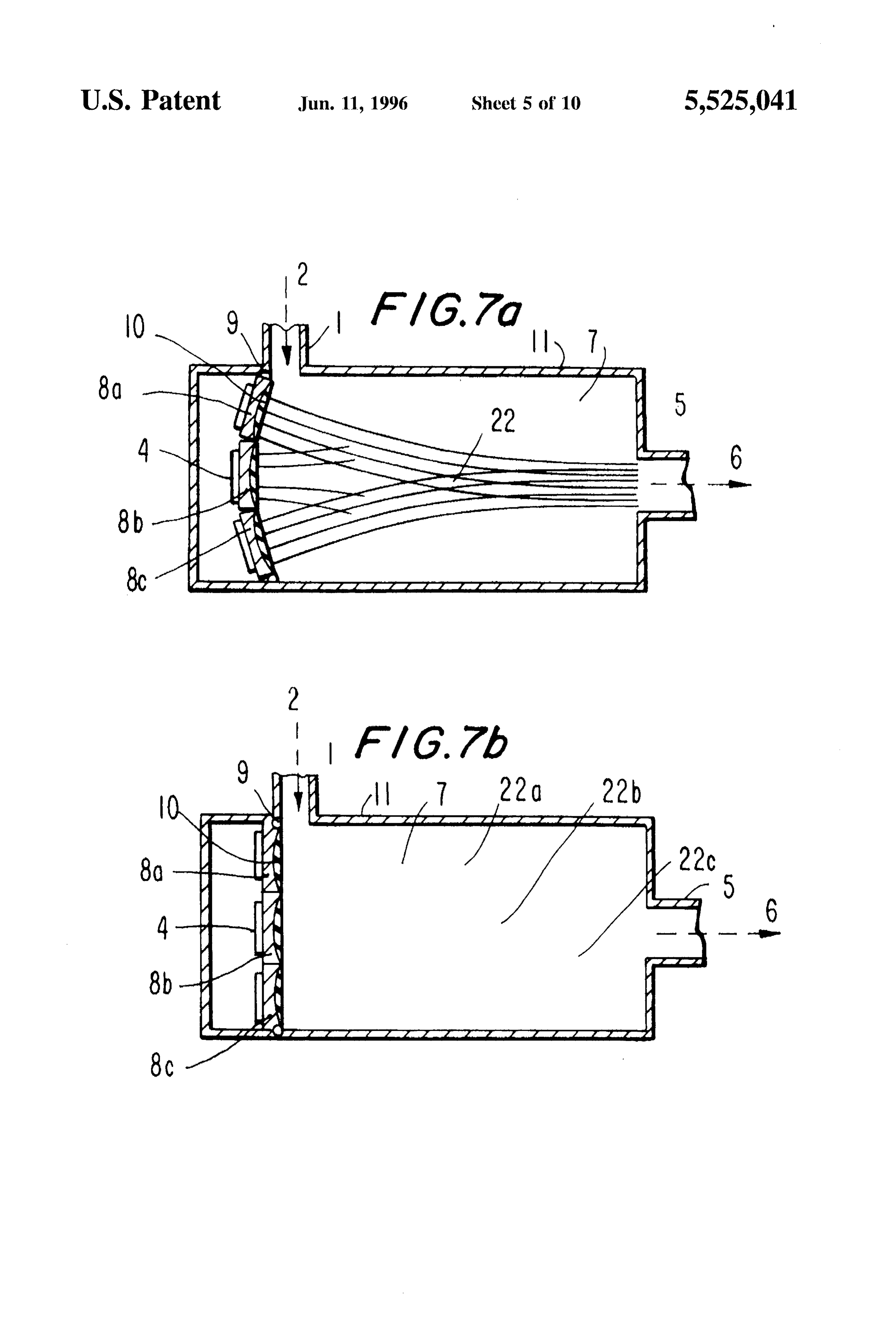
FIG. 1 is a simplificd scctional side vicw of thc basic structure of thc preferrcd cmbodimcnt of thc prescnt invcn 15 tion; 'IORY O OPERATION FIG. 2a illustrates a simplifical scctional side vicw of the A momcntum transfer pump is disclosed without using basic structure of the present invention of FIG. 1 with a well any moving mechanical parts. The pump uses acoustic defined tapcircd channcluscd to guide a focuscd ultrasound radiation forces to transfer momentum by clastic and inclas bcam through thc medium; 20 tic collisions of phonons to thc mcdium (fluid moleculcs) FIG. 2b illustratics a simplificcd scctional side vicw of resulting in a flow gradicnt of thc medium in a resultant another cmbodiment of thc invention of FIG.2a whercin thc direction opposite thc acoustic cncrgy source (transduccr). It outlet is in thc sidc wall of thc chamber; can bc miniaturized; thc fluid medium is totally isolatcd FIG. 3 illustrates a simplifical scctional basic structure of from thc transduccr mcans, and is silent with no convcn FIG. 1 with a tapcircd focusing guide along with an extended 25 tional vibration,
How Zonc and acoustic wave trap to prevcnt reflect.cd waves This momentum transfer pump can be used as a direct from rc-cntering thc pump chambcr; rcplaccmcnt for any conventional pump application and uscs FIG. 4 is a schcmatic diagram illustrating how acoustic far less clectrical cncrgy for an cquivalent mechanical radiation pressurc cxcrts a forcc on a stationary objcct in a 30 pumping operation. If it docs ?ail in opcration, it can bc control volumc-for purposes of thcorctical analysis; casily repaired by replacing the few parts inccded for opcra FIG. 5a is a front vicw of a special plano-parabolic tion, namcly either thc drive clcctronics or thc acoustic transduccr, compriscd of two di?crcnt pic/Oclcctric trans transducer itsc?. Furthermore, using micro-clectronic cir duccr clemcnts on a common substratc. which results in a cuitry, thc transducer and its associated drivc clcctronics can compositic frcqucncy range much wider in spectrum that a 35 bc integratcd into onc hybrid componcint, truly allowing for a pump systcm with two major parts; a transducer assembly single transducer clcmcnt; and the pump housing or chamber. The main housing or FIG, 5b is a cut-away perspcctive vicw of the transducer chambcritisclf can bc a single mouldcd or machined part and of FIG. 5a showing its two individual piczoclectric trans as such would not ?ail, for it is simply a mctal or plastic ducer clements having two separate rcsonant frcquencies; cncloscd chambcr. Such a solid static pump functions via the FIG. 5c is a resultant frcquicncy bandwidth curve of thc 40 momentum imparted by a specially designcod ultrasonic transducer shown in FIG. 5b showing how the overall transducer clcmcnt. However, it may includc for its opera frcquency bandwidth is increased by this dual clement tion other mcthods of gcncrating ultrasonic radiation forces. plano-parabolic cchniquc; To understand the modc of operation of this pump, onc FIG. 6 shows in a simplifical scctional side vicw another must consider thc phcnomenon of a nondissipative ?luid. The embodiment of the basic structure of thc prescnt invention 45 medium can bc trcatcd as a continuous onc. This approxi with a special reflector arrangcmcnt-called an impcdance mation is at all times valid, cxcept for an extremcly rare?icd transformcr-for reflecting various wavcs of various frc gas, or for a solid when the wavclengths of the waves arc quencics; comparable with thc inter atomic distances. FIG. 7a shows in a simplifical scctional side vicw another 50 if the problem can be considered one dimensional by cmbodiment of the basic structure of the present invention assuming that a wavc of very broad front is travcling in the using a multi-clemcnt transducer array with parabolic align positive X direction such that all motions at the coordinate ment for incrcascd flow ratics; valuc x arc the same, regardless of thcy and Z, coordinates, FIG.7b shows in a simplifical sectional sidc view another This type of disturbance is known as a planc wavc. cmbodiment of thc basic structure of the present invention 55 Whcn a sound wave is propagated, thc particles making using a multi-clement transducer array with parallcl planc up the mcdium arc displaccd form thcir rest or cquilibrium alignment for increascd flow ratics; positions. If thc displaccmcnt of thc particle is along thclinc FIG. 8a shows in a simplifical scctional side vicw anothcr of the direction of propagation of thc wave, wc call thc wavc cmbodiment of the basic structure of the prescnt invention longitudinal. Most sound wavcs impacting on ?luids are which is multi-chambcrcd and uni-directional and using at 60 longitudinal in charact.cr. If thcsc displaccments arc at right least onc transducer per chambcr, but not restrict.cd to onc anglcs to thc direction of propagation of thc wave, the wave transduccr per chamber; to bc uscd in complex pumping is termed transverse. Usually transvcrsc waves arc more arrangements; common in very viscous liquids, but their importance in FIG. 8b shows in a simplificd scctional side vicw another acoustics is primarily limited to sound wavcs in solids. cmbodiment of the basic structure of thc prescnt invention 65 Acoustic radiation forces werc first measurcd in 1903 and which is multi-chambered and bi-directional and using at in reccnt years, thc practical importance of acoustic mca lcast onc transduccr per chambcr, but not restrict.cd to onc surcments of this typc arc scen in both thc non-destructive
Page 15
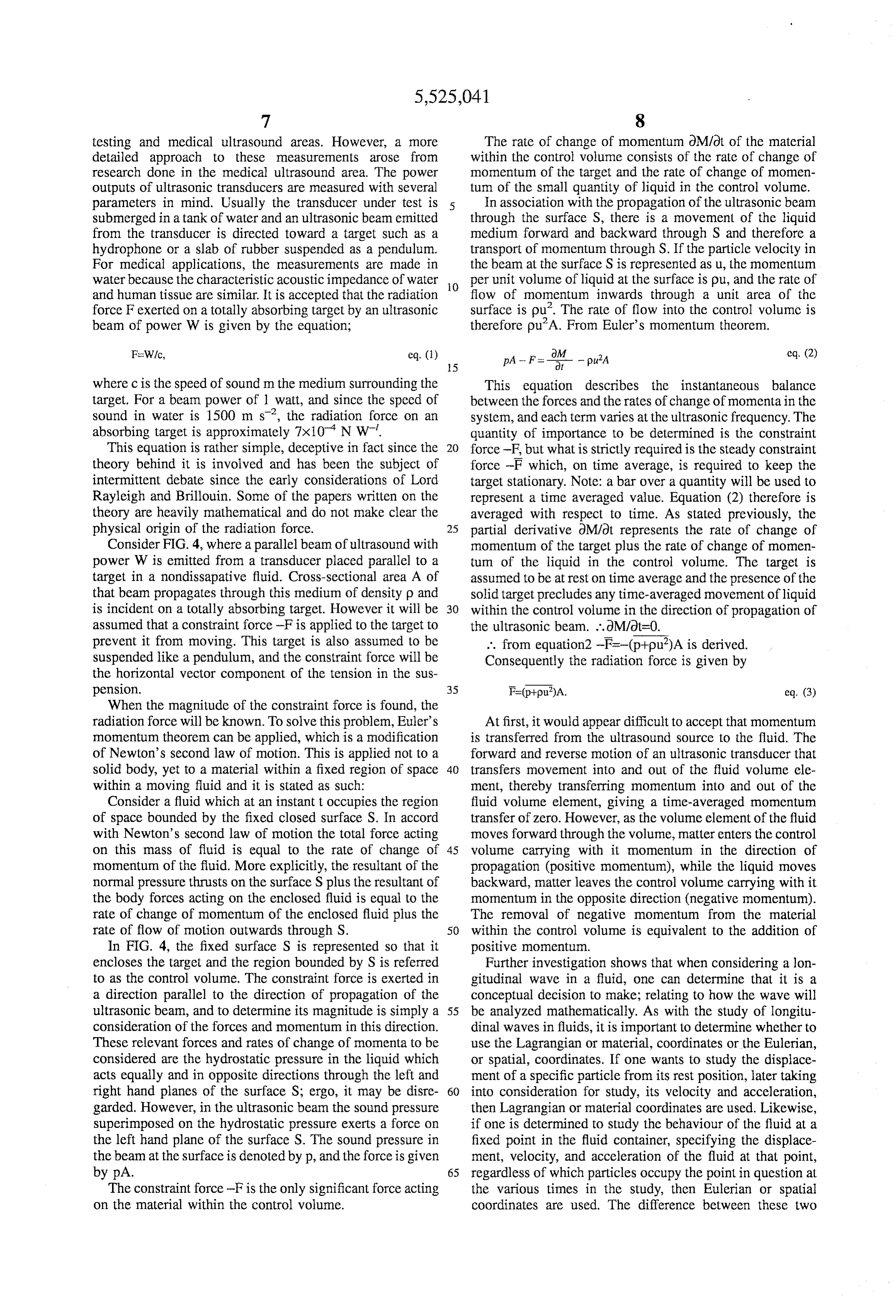
testing and medical ultrasound areas. However, a more The rate of change of momentum OM/ot of the material detailed approach to these measurements arose from within the control volume consists of the rate of change of research done in the medical ultrasound area. The power momentum of the target and the rate of change of momen outputs of ultrasonic transducers are measured with several tum of the small quantity of liquid in the control volume. parameters in mind. Usually the transducer under test is In association with the propagation of the ultrasonic beam submerged in a tank of water and an ultrasonic beam emitted through the surface S, there is a movement of the liquid from the transducer is directed toward a target such as a medium forward and backward through S and therefore a hydrophone or a slab of rubber suspended as a pendulum. transport of momentum through S. If the particle velocity in For medical applications, the measurements are made in the beam at the surface S is represented as u, the momentum water because the characteristic acoustic impedance of water O per unit volume of liquid at the surface is pu, and the rate of and human tissue are similar. It is accepted that the radiation flow of momentum inwards through a unit area of the force F exerted on a totally absorbing target by an ultrasonic surface is pu'. The rate of flow into the control volume is beam of power W is given by the equation; therefore pu’A. From Euler's momentum theorem.
where c is the speed of sound m the medium surrounding the This equation describes the instantaneous balance target. For a beam power of 1 watt, and since the speed of between the forces and the rates of change of momentain the sound in water is 1500 m s”, the radiation force on an system, and each term varies at the ultrasonic frequency. The absorbing target is approximately 7x10' N. W. quantity of importance to be determined is the constraint This equation is rather simple, deceptive in fact since the force -F, but what is strictly required is the steady constraint theory behind it is involved and has been the subject of force -F which, on time average, is required to keep the intermittent debate since the early considerations of Lord target stationary. Note: a bar over a quantity will be used to Rayleigh and Brillouin. Some of the papers written on the represent a time averaged value. Equation (2) therefore is theory are heavily mathematical and do not make clear the averaged with respect to time. As stated previously, the physical origin of the radiation force. 25 partial derivative dM/dt represents the rate of change of Consider FIG. 4, where a parallel beam of ultrasound with momentum of the target plus the rate of change of momen power W is emitted from a transducer placed parallel to a tum of the liquid in the control volume. The target is target in a nondissapative fluid. Cross-sectional area A of assumed to be at rest on time average and the presence of the that beam propagates through this medium of density p and solid target precludes any time-averaged movement of liquid is incident on a totally absorbing target. However it will be 30 within the control volume in the direction of propagation of assumed that a constraint force -F is applied to the target to the ultrasonic beam. ..OM/dt=0.
prevent it from moving. This target is also assumed to be ... from equation2 -F-(p-pu?)A is derived. suspended like a pendulum, and the constraint force will be Consequently the radiation force is given by the horizontal vector component of the tension in the sus pension. 35 F=(p+pu)A. eq. (3) When the magnitude of the constraint force is found, the radiation force will be known. To solve this problem, Euler's At first, it would appear difficult to accept that momentum momentum theorem can be applied, which is a modification is transferred from the ultrasound source to the fluid. The of Newton's second law of motion. This is applied not to a forward and reverse motion of an ultrasonic transducer that solid body, yet to a material within a fixed region of space 40 transferS movement into and out of the fluid volume ele within a moving fluid and it is stated as such: ment, thereby transferring momentum into and out of the Consider a fluid which at an instant t occupies the region fluid volume element, giving a time-averaged momentum of space bounded by the fixed closed surface S. In accord transfer of Zero. However, as the volume element of the fluid with Newton's second law of motion the total force acting moves forward through the volume, matter enters the control on this mass of fluid is equal to the rate of change of 45 volume carrying with it momentum in the direction of momentum of the fluid. More explicitly, the resultant of the propagation (positive momentum), while the liquid moves normal pressure thrusts on the surface S plus the resultant of backward, matter leaves the control volume carrying with it the body forces acting on the enclosed fluid is equal to the momentum in the opposite direction (negative momentum). rate of change of momentum of the enclosed fluid plus the The removal of negative momentum from the material rate of flow of motion outwards through S. 50 within the control volume is equivalent to the addition of In FIG. 4, the fixed surface S is represented so that it positive momentum.
encloses the target and the region bounded by S is referred Further investigation shows that when considering a lon to as the control volume. The constraint force is exerted in gitudinal wave in a fluid, one can determine that it is a a direction parallel to the direction of propagation of the conceptual decision to make; relating to how the wave will ultrasonic beam, and to determine its magnitude is simply a 55 be analyzed mathematically. As with the study of longitu consideration of the forces and momentum in this direction. dinal waves in fluids, it is important to determine whether to These relevant forces and rates of change of momenta to be use the Lagrangian or material, coordinates or the Eulerian, considered are the hydrostatic pressure in the liquid which or spatial, coordinates. If one wants to study the displace acts equally and in opposite directions through the left and ment of a specific particle from its rest position, later taking right hand planes of the surface S; ergo, it may be disre 60 into consideration for study, its velocity and acceleration, garded. However, in the ultrasonic beam the sound pressure then Lagrangian or material coordinates are used. Likewise, superimposed on the hydrostatic pressure exerts a force on if one is determined to study the behaviour of the fluid at a the left hand plane of the surface S. The sound pressure in fixed point in the fluid container, specifying the displace the beam at the surface is denoted by p, and the force is given ment, velocity, and acceleration of the fluid at that point, by pa. 65 regardless of which particles occupy the point in question at The constraint force -F is the only significant force acting the various times in the study, then Eulerian or spatial on the material within the control volume. coordinates are used. The difference between these two
Page 16
mcthods is gencrally of importance only when the intensity this radiation scts up a travcling wavc within thc chamber 11 of the sound wave is very high-infinitic amplitude sound or which contains cncrgy and momentum. As this travcling nonlincar acoustics. With intcrest in thc arca of nonlinear wavc intcracts with the mcdium 7 through the components acoustics relating to thcgcneration of Sonoluminescencc for of absorption, scatt.cring, and nonlincar propagation, it trans cold fusion cxperiments, the realization of thc difference ?ers its cnergy and longitudinal momentum to the medium 7. betwccn these two approachcs is of importance, Summing This intcraction is constant; and instantly causcs pumping this up, Lagrangian variables, rcfcr to a moving mass action to occur. Thc cfcctivc radiation pressure gencratcd by clcment of liquid and not to a ?ixcd point in space; Eulcrian thc transducer 8 and coupled to the mcdium 7 is directly variables refer to a fixed point x in spacc which may bc proportional to thc acoustic power transmitted per unit limc occupied by different mass clements of thc medium (liquid) 10 through a unit area of the coupling devicc 10, which couplcs at different times. Notic: this theoretical rcvicw is referenced the transduccr cncrgy to thc mcdium 7. Ilowever it is also from an article by Dcak titled, "Theory and Dcsign Concepts dc crimined in part by a reflection coc?licicnt, This reflection of Ultrasonic Sources,' COLD FUSEON magazine vol. 1 cocflicient is dictcrmined by thc ratio of thc product of the number (4), September 1994. density and velocity of thc coupling medium 10 and the According to a gencral form of the invention The respon 5 density and vclocity of thc fluid medium 7 to be pumpcd. If sive clement of thc momentum transfer pump is an ultra acoustic phonons from thc transducer source 8 arc totally sonic source in gencral. It may, howcver be a specific source absorbed (inclastic collisions bctwccn phonons and fluid such as a piezoclcctric transducer, an electrostriction trans molecules) by thc mcdium 7, then the radiation pressure is ducer, stimulatcd Brillouin cmission sourccs, surface gen cqual to thc ratio of thc power cmitted from the transducer cration in Quart, thin-film pic/oclcctric transduccrs, deplc 20 8, to thc wave vclocity in this mcdium 7; or in summary, it tion layer transducers, or diffusion layer transducers. is cqual to the cncrgy density. If acoustic phonons from source 8 arc totally reflected (clastic collisions bctwccn
DESCRIPTION AND OPERATION OF phonons and fluid molcculcs) by thc mcdium7, the radiation INVENTION pressure is cqual to thc ratio of twicc the power cmillcd from 25 the transducer, to thc wavc velocity in this mcdium 7; or in
In thesc drawings, like re?crcnce numerals arc uscd to summary, it is cqual to twice the cncrgy density, The real indicatc like clements. Accordingly only thosc componcints resultant radiation pressure falls somcwhere on an time that arc different than thc corrcsponding componcints arc avcragcd valuc for this imparted longitudinal momentum to hcrcina?ter describcd. the mcdium 7. The cncrgy pcrunit volume of fluid is dcrived The drawing of FIG. 1 illustratics a pre?crred cimbodimcnt 30 from a directly proportional relationship amongst thc acous of thc present invention. In its broadcst scnsc, the momen tic frcquency, fluid dcnsity, velocity of sound through thc tum transfer pump comprises a pre?erably cylindrical shaped medium 7, the fluid particle (molccular) displaccment, and chamber or chamber means 11 having an input port or inlet further it is inversely proportional to thc wavclength of the 1 for fluid cntry into to the main body of the chamber 11 and cmitted acoustic wave from transducer 8. By ncccssary an output port or outlet 5 which is disposed at thc sccond cnd 35 design, the acoustic couplcr 10 does not interact with thc of the chamber 11 and which allows fluid to cxit or pass from cmitted phonons to any significant degree and is csscntially said chamber 11, Furthermore, fluid 7 containcol within thc transparcnt to the acoustic waves; additionally it prevents chamber acts as thc mcdium for thc transfer of acoustic any contact of thc fluid mcdium 7 with the cxternal cnvi radiation pressure from a convcntional disc shaped piczo ronment, and this featurc of thc invcntion serves an impor electric transduccr clemcnt 8 having a parabolic front ?acc AO tant purposc where thc absence of contamination is vital. planc disposcd at one cnd, the first cind, of the chamber 11, Iack of contamination is commonly required in thc mcdical to molecules of the fluid mcdium 7. The transducer 8 is and pharmaccutical scctors. Thc chamber 11 forms a non driven by conventional clcctronic drive circuitry 4 which resonant cavity at thc opcrating frcquency of thc transducer generates clectrical pulses to cnergi/c the pic/oclcctric 8. In this cmbodiment thc sidc walls of the chamber 11 arc transducer clcment 8; thcy form an acoustic source for 45 devoid of any outlets.
providing an acoustic radiation ficlic which cmanates acous FIG. 2a is a drawing of another embodiment of thc pump tic phonons as described in more detail below. Thc clcc which utilizes a tapcircd guide 12 which scrves to steer thc tronic drive circuitry 4 is conncctcd to an clectrical powcr medium 7 flow gradicnt and thc acoustic radiation in a source (not shown) through clectrical criminals 3. A trans concentratcd dircction which is oppositic that of thc trans duccr means comprisc the drive circuitry 4 and thc trans SO ducer 8. An outcr housing 13 with removable rear cover 14 ducer 8. An O-ring 9 is disposcd along thc periphery of the is disposcd over the chambcr 11, transducer 8 and thc drive transduccr 8 to prevent fluid cscaping into the circuitry's circuitry 4. This tapcircd guidc 12 cstablishes a very high housing 14 which is illustratcd in FIG.2a. The piezoclcctric radiation cncrgy density which rcduccs the total chamber transducer 8 is clectrically stimulatcd by thc drive circuitry path length otherwisc requircd to achicvc the ncccssary 4 and it in turn vibratics at its natural resonant frequency; this 55 momcntum interaction. With increascd radiation cncrgy transducer 8 can cither bc of a high-Q matrosy band width dcnsity, non lincarity of the mcdium 7 alters the radiation typc, or a high-Q broadband width typc; but thc transduccr cncrgy wave thus creating radiation harmonics. Thesc high 8 is not restrict.cd to only thcsc typcs. In thc broadcst sensc frcqucncy harmonic radiation components arc propagated however, thc transduccr 8 could, in general bc any device and absorbed within the mcdium 7 and if thc energy levcls that can cffectively transform clcctrical cncrgy into 60 cmittcd from thc transducer 8 arc of sufficient amplitudc, mcchanical cncrgy. The transducer 8 is acoustically coupled cavitation will occur when the rarefactive acoustic pressure to the medium 7 by a conventional coating or acoustic rcsults in thc formation of a vapour phase of the mcdium m coupling devicc 10 which cnables the maximum transfer of the ?low gradicnt. Cavitation is thc proccss of forming acoustic radiation pressurc into that medium7. The radiation micro-bubbles in a liquid by gencrating intcinsc ultrasound pattern emittcd (phonons) from the transducer 8 is that of a 65 wavcs. When a cavity (gas or vapor bubble) is creatcd and longitudinal wave of some nature (preferably a simplc trapped in a ?luid by an influentially strong ultrasound ficlal, harmonic wavc although a complex wavc can be used) and it undergocs nonlincar oscillations that can concentrate the
Page 17
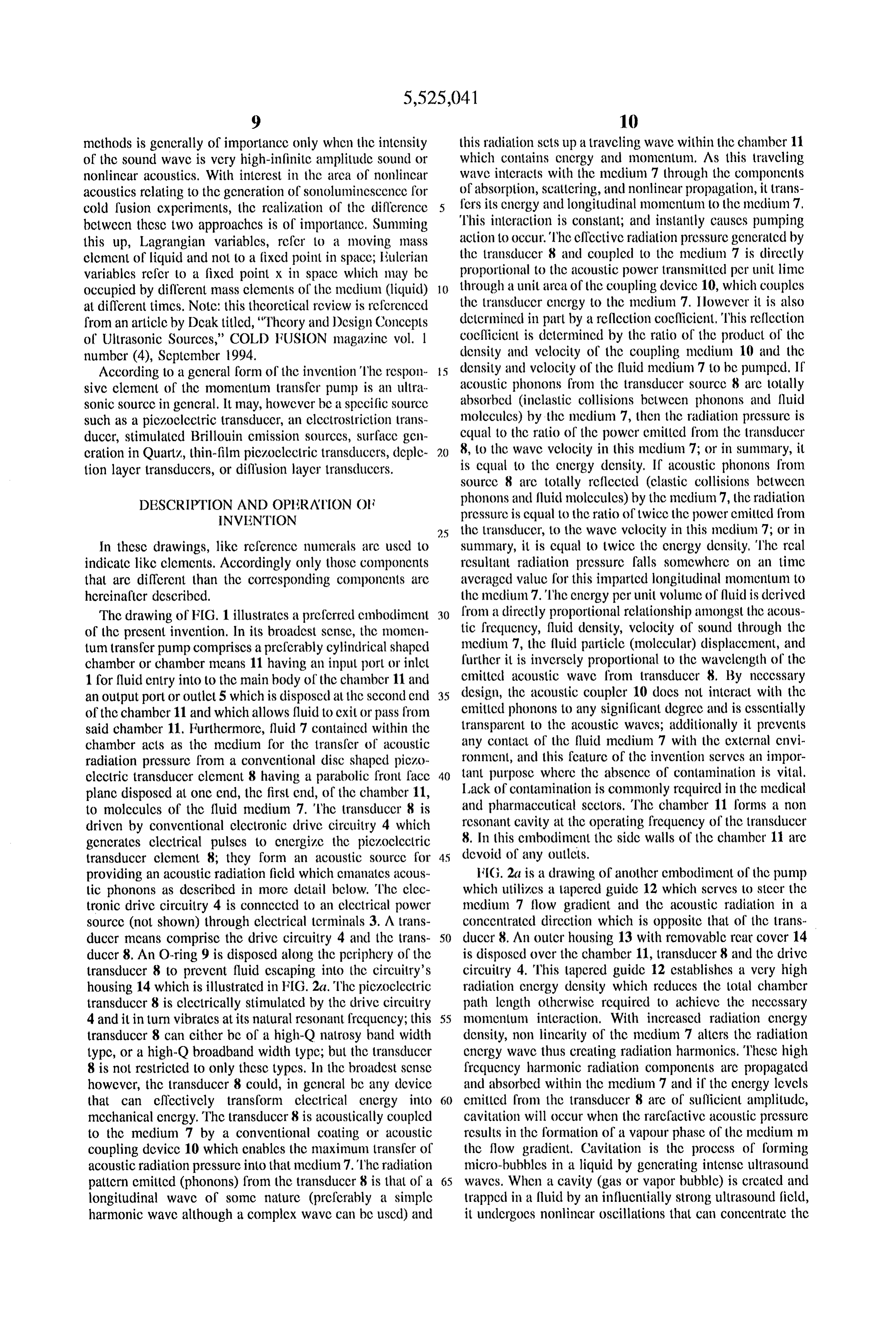
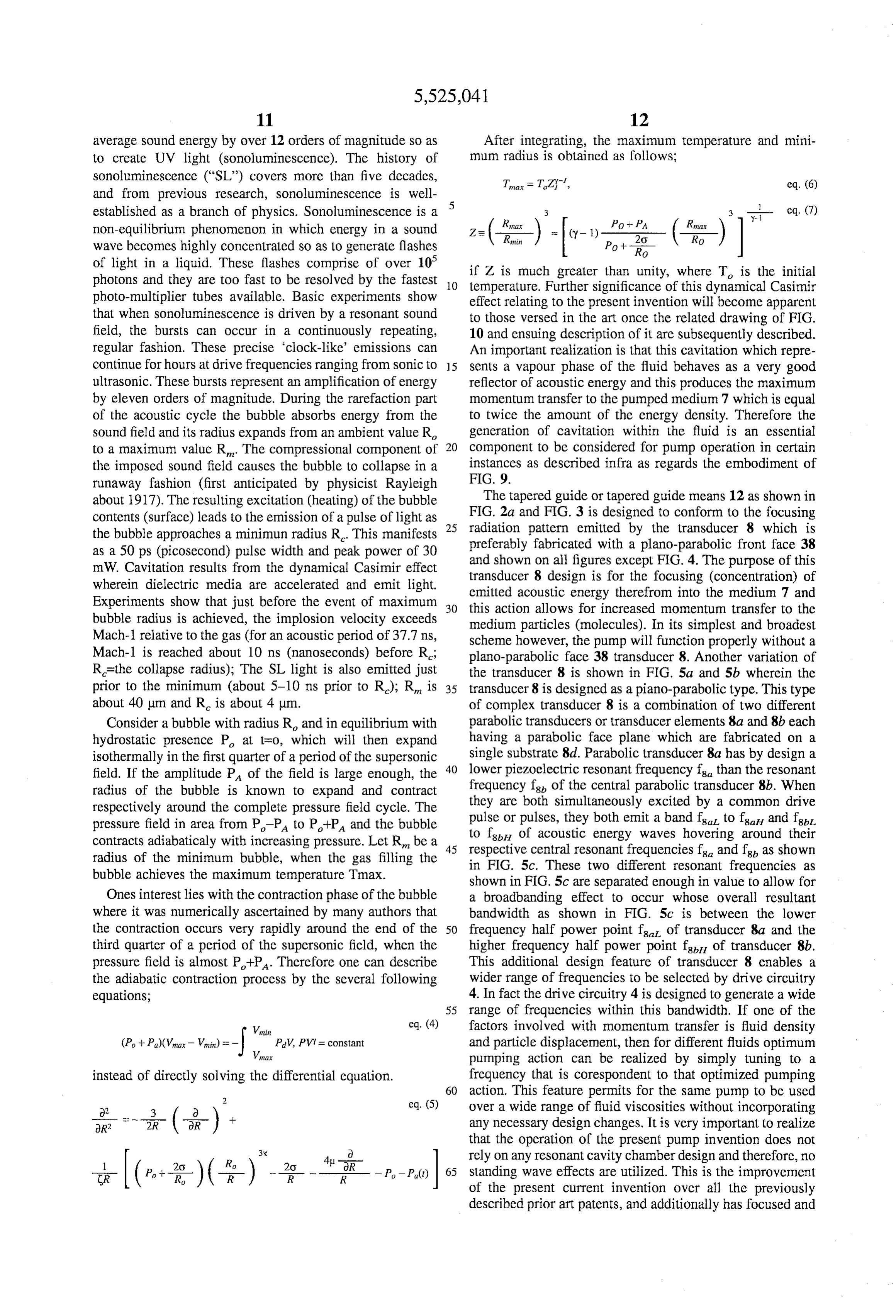
average sound energy by over 12 orders of magnitude so as After integrating, the maximum temperature and mini to create UV light (sonoluminescence). The history of mum radius is obtained as follows: Sonoluminescence ("SL') covers more than five decades, Ta = T.Z, eq. (6) and from previous research, sonoluminescence is well 5 established as a branch of physics. Sonoluminescence is a Rmay
non-equilibrium phenomenon in which energy in a sound Z= --) = (-1)-P+ - - O wave becomes highly concentrated so as to generate flashes iii.
of light in a liquid. These flashes comprise of over 10 if Z is much greater than unity, where T is the initial photons and they are too fast to be resolved by the fastest O temperature. Further significance of this dynamical Casimir photo-multiplier tubes available. Basic experiments show effect relating to the present invention will become apparent that when Sonoluminescence is driven by a resonant sound to those versed in the art once the related drawing of FIG. field, the bursts can occur in a continuously repeating, 10 and ensuing description of it are subsequently described. regular fashion. These precise 'clock-like' emissions can An important realization is that this cavitation which repre continue for hours at drive frequencies ranging from sonic to 15 sents a vapour phase of the fluid behaves as a very good ultrasonic. These bursts represent an amplification of energy reflector of acoustic energy and this produces the maximum by eleven orders of magnitude. During the rarefaction part momentum transfer to the pumped medium7 which is equal of the acoustic cycle the bubble absorbs energy from the to twice the amount of the energy density. Therefore the sound field and its radius expands from an ambient value R. generation of cavitation within the fluid is an essential to a maximum value R. The compressional component of 20 component to be considered for pump operation in certain the imposed sound field causes the bubble to collapse in a instances as described infra as regards the embodiment of runaway fashion (first anticipated by physicist Rayleigh FIG. 9.
about 1917). The resulting excitation (heating) of the bubble The tapered guide or tapered guide means 12 as shown in contents (surface) leads to the emission of a pulse of light as 25 FIG. 2a and FIG. 3 is designed to conform to the focusing the bubble approaches a minimun radius R. This manifests radiation pattern emitted by the transducer 8 which is as a 50 ps (picosecond) pulse width and peak power of 30 preferably fabricated with a plano-parabolic front face 38 mW. Cavitation results from the dynamical Casimir effect and shown on all figures except FIG. 4. The purpose of this wherein dielectric media are accelerated and emit light. transducer 8 design is for the focusing (concentration) of Experiments show that just before the event of maximum 30 emitted acoustic energy therefrom into the medium 7 and this action allows for increased momentum transfer to the bubble radius is achieved, the implosion velocity exceeds medium particles (molecules). In its simplest and broadest Mach-1 relative to the gas (for an acoustic period of 37.7 ns, scheme however, the pump will function properly without a Mach-1 is reached about 10 ns (nanoseconds) before R; plano-parabolic face 38 transducer 8. Another variation of R=the collapse radius); The SL light is also emitted just the transducer 8 is shown in FIG. Sa and Sb wherein the prior to the minimum (about 5-10 ns prior to R); R is 35 transducer 8 is designed as a piano-parabolic type. This type about 40 am and R is about 4 um. of complex transducer 8 is a combination of two different Consider a bubble with radius R and in equilibrium with parabolic transducers or transducer elements 8a and 8b each hydrostatic presence P, at t=o, which will then expand having a parabolic face plane which are fabricated on a isothermally in the first quarter of a period of the supersonic single substrate 8d. Parabolic transducer 8a has by design a field. If the amplitude PA of the field is large enough, the 40 lower piezoelectric resonant frequency f. than the resonant radius of the bubble is known to expand and contract frequency f. of the central parabolic transducer 8b. When respectively around the complete pressure field cycle. The they are both simultaneously excited by a common drive pressure field in area from P-PA to P+P and the bubble pulse or pulses, they both emit a band fall to far and fs contracts adiabatically with increasing pressure. Let R be a 45 to fs of acoustic energy waves hovering around their respective central resonant frequencies ? and fs, as shown radius of the minimum bubble, when the gas filling the in FIG. 5c. These two different resonant frequencies as bubble achieves the maximum temperature Tmax. shown in FIG. 5c are separated enough in value to allow for Ones interest lies with the contraction phase of the bubble a broadbanding effect to occur whose overall resultant where it was numerically ascertained by many authors that bandwidth as shown in FIG. 5c is between the lower the contraction occurs very rapidly around the end of the 50 frequency half power point f of transducer 8a and the third quarter of a period of the supersonic field, when the higher frequency half power point f of transducer 8b. pressure field is almost PHPA. Therefore one can describe This additional design feature of transducer 8 enables a the adiabatic contraction process by the several following wider range of frequencies to be selected by drive circuitry equations, 4. In fact the drive circuitry 4 is designed to generate a wide 55 range of frequencies within this bandwidth. If one of the
Vani fif factors involved with momentum transfer is fluid density
(Pa + Pa)(Vmax - Wnin) = PV, PV = constant and particle displacement, then for different fluids optimum Vmax pumping action can be realized by simply tuning to a instead of directly solving the differential equation. frequency that is corespondent to that optimized pumping 60 action. This feature permits for the same pump to be used
+ q. (5) over a wide range of fluid viscosities without incorporating any necessary design changes. It is very important to realize that the operation of the present pump invention does not
rely on any resonant cavity chamber design and therefore, no 65 standing wave effects are utilized. This is the improvement
(R- (r. Ro ) ( R ) -- - - - - - P -P(t) of the present current invention over all the previously described prior art patents, and additionally has focused and
Page 18
dual frcquency band transducer ?catures. All of the previ pressure dcnsity pattern into the mcdium 7 resulting in thc ously prior art patents relics complcicly on cstablishing intcnsity of the acoustic radiation ?icla being concentratcd at standing waves within the confincs of a resonant chambcr a focal point within thc mcdium 7. In FIG. 7b the cmitted for proper operation. In thc prescnt invention, thc principlc acoustic radiation patterns are represcintcd by parallcl lincs of opcration residcs in the transfer of momentum from thc 22a, 22b, and 22c; whercas with respcct to thc cmbodiment cncrgy containcd in thc cmitted acoustic phonons from the of FIG. 7a, thc acoustic radiation pressure density pattern is transducer 8 to thc mcdium 7 particles; and not the resonant rcpresented by lincs 22.
frcqucncy of the chamber, or thc carc?ul placement of the The present invention can also have a plurality of trans input and output ports relative to the standing wave nodcs ducers configurcd as shown in FIG, 8a and FIG. 8b. Each of and antinodcs cstablishcd within the resonant chamber as is O the plurality of transducers 8a and 8b are placcd within onc cssential with all said prior art patcnts. of thc plurality of chambcrs 11a and 11b, but not restrict.cd In FIG.2b, which is a modification of thc cmbodiment of to any spccific combination of transduccrs and chambers; or FIG. 2a, the medium 7 flow gradicnt and thc acoustic spccific plurality of transducers in a specific plurality of radiation gencratcd by said transducer mcans 8 is stccred by chambers.
thc tapcircd guide 12 which is modifical for this configuration 5 Thc cmbodimcnt shown in FIG, 8b makes it clcar that to cause mcdium 7 fluid flow through an output port 5 bi-directional or parallcl flow is possible with this arrange disposcd in the sidc wall of the chamber 11 near its sccond ment, however it is not restricted to only two different or cnd. parallcl ?lows, but can bc a plurality of directional flows or Referring now to FIG. 3 which shows another improved a plurality of parallel flows. Thc configuration of fluid flow ?cature which clearly 23 illustrates the lack of any conncxion 20 2a to 6a for FIG. 8a from chamber 11a is from input port 1 a with standing wavc pumps or compressor. ln said FIG. 3, a to output port 5a, and in a parallel direction for chambcr 11b linear zone guide 15 is uscd to carry thc mcdium 7 up to an whosc respective fluid flow 2b to 6b is from input port 1b to acoustic wavc trap or wavc trap mcans 16 and through this output port 5b, Now referring to the cmbodimcnt of FIG. 8b Zone to thc output port 5. Since any acoustic wavc cncrgy whercin thc pump chambers 11a and 11b arc situatcd in a not absorbed by thc medium 7 is preventcd from bcing ?ed 25 manner that placcs thcir respectivc transduccrs 8a and 8b in back into thc pump chamber 11 by thc acoustic wavc trap 16 dircctions opposing onc another. This configuration pro and subscqucntly interacting with the primary pumping duccs bi-directional fluid flow 2a to 6a and 2b to 6b. action and therchy reducing thc overall pump cflicicncy, Ilowcver such configuration is not restrict.cd to only bi This result is achieved by usc of the acoustic wave trap 16 directional fluid flow but it can be a plurality of different which comprises an interior attenuation mcdium 17 which 30 directional arrangements. An ancillary cxtension of thc consists of some matcrial with a vcry high acoustic absorp multiple momentum pump is shown in FIG. 8c, wherein thc tion coefficient (i.e. oil or soft rubber) and an incidcnt wall fluid flow 7a from thc top chamber 11a travels to output port 18 at thc sccond cnd of thc chamber means 11 having a low 5a and is further directed into the top chamber output ?low reflection coc?licient of encrgy transfer. Thc purpose of the and valve assembly 28a and the fluid flow 7b from thc wave trap 16 in this cmbodimcnt of the prescnt invention, is 35 bottom chamber 11b travels to output port 5b and is further primarily utilizcd to nullify any development of standing directed into thc bottom chamber output ?low and valve waves within the pump chamber 11 which would interfcrc assembly 28b. Mixture tank or mixing chamber 29 accepts with its propcr opcration. The usc of a wave trap 16 and the differcnt fluids from thc top chamber output flow and standing wave operation as in all thc prior art patcnts valvc assembly 28a and the bottom chamber output ?low and discusscd supra arc mutually cxclusive. In summary thc 40 valve assembly 28b where thc mixture flows through a wave trap absorbs and cancels any wavc encrgy not com mixture output ?low and valve assembly 30. FIG. 8d shows plcticly absorbcd by thc medium 7 in the chamber 11. another cmbodiment, a derivation of FIG, 8b whercin in this FIG. 6 illustrates another cmbodimcnt of the prescnt configuration the opposing dircctional input ports 2a and 2b invention which cxtends the design configuration to cncom of FIG, 8b arc conncctcd to a common mixture tank or pass possible variations in pump geometry. For instance, if 45 mixing chamber 29 for thc purpose of mixing thc di?crcnt thc pump gcometry has to be confincd to a certain circum fluids.
scribcd volumc, and if thc pump chamber physical dimen FIG. 9 represcnts another ancillary pump likc configura sions arc not long enough to insurc complctic absorption of tion of the prescnt invention whcrchy thc previously con thc cmittcd acoustic wave cncrgy, then a scrics of corncr figurcd output port 5 is replaccd with a window or trans cnergy reflectors or cncrgy reflectormcans 20 will reflect the 50 parcnt mcans 24 compriscd of glass or somc similar cmitted cncrgy waves into additional linear Zones or auxil transparent matcrial. With this version of the present inven iary chambers 15a, 15b, and 15c disposed parallel to the tion, water (ILO) is uscd as the mcdium 7 and cnters into thc main pump chamber or main chamber 11, conscqucntly, the chamber 11 by way of the input port 1 and the vent and fluid wavc cncrgy is complctely absorbcd beforc the ?luid cxits input valvc 21, The primary goal of this cmbodiment of the the output port 5. 55 invention is not to have pumping action taking placc, instcad FIG. 7b illustratics another cmbodiment of the prescnt the watcr remains within the chamber for thc purpose of invention which features threc transducers 8a, 8b, and 8c creating cavitation within the water. In opcration a very high disposcd in a parabolic planc so as to providc arcsultant cncrgy dcnsity acoustic radiation pressure ?icla is gencratcd focuscd beam radiation ficla.; however this configuration is by an incrcascd powcr pulsc cmanating from thc drivc not restrict.cd to any specific number of such transducers. 60 circuitry 4 and applicd to thc transduccr 8. Thc cnergy The purpose of this featurc of thc prescnt invention is to density is further increascd by utilizing a tapcircd guide 12 incrcase the cmitted acoustic radiation pressure into thc and a parabolic transducer 8 which furthcr concentratics thc medium 7, thus producing increascd flow ratics to the acoustic cncrgy density. When the acoustic cncrgy dcnsity medium 7. The alignment of this plurality of transducers 8 increascs bcyond a certain valuc, cavitation occurs within is not restricted to any specific alignment configuration. As 65 the water and thcsc micro-bubbles (cavitation) form a cluster shown in FIG. 7a, thc parabolic face planc alignment 23 near thc window 24. Thcsc micro-bubbles cxpand and configuration produces increases in the acoustic radiation contract in tunison with thc cmitted ultrasound and during
Page 19
the collapse phase of this activity blue light is emitted plurality permanent magnetic fields for various design rea through the window 24. This phenomenon is a form of sons. It should be apparent to anyone skilled in such art that coherent sonoluminescence; which stems from the dynami a plurality of non-metallic or metallic coiled tubing arrange cal Casimir effect wherein dielectric media are accelerated ments could be used in conjunction with a plurality of and emit light. A bubble in water is seen as a hole in a transducers and a plurality of chambers with a plurality of dielectric medium. Water is a polar molecule with a high electromagnetic fields 27 or a plurality of permanent mag dipole moment and responds to incident light as an oscil netic fields for any possible design configuration or con lating dipole. If a group of water molecules is ordered into figurations.
a helical structure of an axial extent greater that the wave In summary, the above described embodiment utilizes a length of blue 26 light where the photon energy -3.3 eV and O pump as described previously; which pump is surrounded by if the individual molecules are oriented so that the dipole an externally generated magnetic field for the purpose of moment vector of the molecules is generally pointing in the providing magnetic lines of force directly through the cham incident light direction, the group in unison is excited at the ber means 11. The pump fluid medium 26 is a liquid metal frequency of incident light. This sonoluminescence may be and as it moves through the magnetic field it creates an a highly ordered arrangement of water molecules in a liquid 15 electric current flow through the liquid metal. Such an crystalline state scattering incident light in the Raman band. embodiment, using ultrasound energy, can be used to gen However, the sound wave is important. In the expansion, the erate electricity.
molecular order is lost because the intermolecular spacing Although various embodiments of the present invention exceeds the range of electrostatic interaction. However, in have been described and illustrated herein, it is recognized compression the molecules are confined to a spherical 20 that modifications and variations may readily occur to those skilled in the art.
geometry and the molecules are ordered into a configuration What is claimed is:
in resonance with the incident light. This blue light in phase 1. A pump comprising:
with the ultrasonic pulsing is a cooperative lasing action.
The sonoluminescence lasing action, collectively termed a a chamber means for receiving a medium to be pumped, blue water laser, may amplify the energy of the incident blue 25 said chamber having first and second ends and an inlet light because of the molecular resonance and represent an and an outlet; and energy gain in the reflected blue light. transducer means disposed at said first end for providing FIG. 10 represents another embodiment of this invention, a traveling wave within said medium which imparts namely a method of generating an electrical current within momentum to said medium whereby said medium a liquid metallic medium 26. The premise for operation of 30 passes through said outlet by said momentum. this apparatus relating to the present invention utilizes a 2. The pump as recited in claim 1, wherein said outlet is liquid metallic medium 26 which is made to flow by the disposed at said second end of said chamber. previous methods set forth in the above descriptions of 3. The pump as recited in claim 1, wherein said transducer FIGS 1-8. means and said outlet of said chamber means being disposed An external electromagnetic field coil 27 is wound around 35 opposite one another.
the outside of the chamber 11 and an electromagnetic field 4. The pump as recited in claim 1, wherein said chamber is established throughout the liquid metallic medium 26 means form a nonresonant cavity at the frequency of said therein. It should be apparent that for any number of design transducer means.
considerations either an electromagnetic field coil 27 could 5. The pump as recited in claim 1, wherein the sides of be used or a permanent magnetic field can be used; both 40 said chamber being devoid of any outlet(s). provide a magnetic means. However there is no restriction 6. The pump as recited in claim 1, wherein said inlet of on the present invention to the number of electromagnetic said chamber means is disposed near said first end of said fields or permanent magnetic fields established for this or chamber means whereby said medium is drawn into said any other purpose of the invention. As the acoustic energy is chamber means.
emitted from transducer 8 there is a flow gradient set up 45 7. The pump as recited in claim 1, further comprising at within the liquid metal medium 26 and as this liquid metal least one chamber means and at least one transducer means medium flows through the electromagnetic field created by disposed at said first end.
field coil 27 and an electric current is induced therein by the 8. The pump as recited in claim 1, further comprising a field coil 27 which begins to flow within the liquid metal plurality of transducer means disposed at said first end. medium 26. The How of this induced electric current is in 50 9. The pump as recited in claim 1, wherein said chamber the same direction of the pumped fluid flow 6 and travels means has a cylindrical shape.
through a connecting means connected between the outlet 5 10. A pump as recited in claim 1, wherein said energy and the inlet 1. The connecting means loop is through a first wave being a traveling wave.
nonmetallic or metallic valve 32 and also through the 11. A pump as recited in claim 1, wherein said energy nonmetallic or metallic output tubing 34 and in turn con 55 wave being ultrasound.
tinuing on through a second nonmetallic or metallic valve 12. A pump as recited in claim 1, wherein said outlet is 32. It then passes into the nonmetallic or metallic coiled disposed on the side of the chamber means and near its tubing where it cycles out through a nonmetallic or metallic second end.
valve assembly 31 where it eventually passes through non 13. A pump as recited in claim 1, wherein said chamber metallic or metallic tubing 33 and to inlet valve which is the 60 has a longitudinal axis, and wherein said transducer means initial reentry point for a new cycle of flow. With this provides a longitudinal energy wave within said medium embodiment of the present invention a single transducer 8 is which imparts longitudinal momentum in a direction along used but a plurality of transducers 8 can be incorporated for the longitudinal axis of said chamber means to said medium various design reasons. Likewise there could be a plurality whereby said medium passes through said outlet by said of chambers incorporated for various design reasons, or any 65 longitudinal momentum.
combination of a plurality of transducers and a plurality of 14. A pump as recited in claim 1, wherein said chamber chambers with a plurality of electromagnetic fields 27 or a means receives a liquid medium to be pumped and said
Page 20
transducer mcans provides a wave within said liquid passes through said outlet by said momentum, wherein medium which imparts momentum to said liquid mcdium said transduccr means has a parabolic ?acc planc wherchy said liquid mcdium passcs through said outlet by whereby the intensity of the acoustic radiation ?icld is said momcntum, concentrated at a focal point thcreby increasing the 15. A pump comprising: density of acoustic cncrgy within the medium, a chamber means for recciving a medium to be pumpcd, 20. A pump comprising:
said chamber having first and sccond cnds and an inlct a chamber mcans for ccciving a mcdium to bc pumpcd, and an outlet; and said chamber having first and sccond means at an inlct transducer means disposcd at said first end for providing O and an outlct; and an encrgy wave within said medium which imparts transducer mcans disposed at said first end for providing momentum to said medium whereby said medium an encrgy wavc within said medium which imparts passes through said outlet by said momcntum, whercin momentum to said mcdium wherchy said mcdium said sccond cnd of said chambcr mcans has a non passes through said outlet by said momentum, wherein rc?l.ccting surface. 5 said transducer mcans comprises a substrate upon 16. A pump comprising: which two transducer clcments arc formcd, cach of said a chamber mcans for receiving a mcdium to bc pump, said transducer clcmcnts having a parabolic ?acc plane with chamber having first and sccond cnds and an inlcl and a different resonant frcquency whereby an outlet; and the resultant resonant bandwidth of said two transducer
transducer mcans disposcd at said first cind for providing mcans is grcatcrthan thc bandwidth of cither of thc two an encrgy wave within said medium which imparts transduccr clomcnts.
momentum to said medium wherchy said mcdium 2. A pump comprising:
passcs through said outlet by said momcntum, whercin a chambcr means for recciving a medium to bc pumpcd, said inlct means comprises an acoustic sourcc for 25 said chamber having first and sccond mcans at an inlct providing an acoustic radiation ?iclc which cmanates and an outlct; and acoustic phonons. transducer mcans disposed at said first cind for providing 17. A pump comprising: an energy wave within said mcdium which imparts a chamber means for receiving a mcdium to be pumpcd, momentum to said mcdium whcrchy said mcdium said chamber having first and sccond cnds and an inlict passes through said outlet by said momentum, further and an outlet; and including a mixing chamber connectcd to said input transducer means disposcd at said first cind for providing port of said chamber means for mixing at lcast two an cnergy wave within said mcdium which imparts mcdiums.
momentum to said mcdium wherchy said mcdium 35 22. A pump comprising:
passcs through said outlet by said momcntum, further a chamber means for recciving a mcdium to bc pump, said comprising chambcr having first and sccond means at an inlct and a tapcircd guidc means disposcod within said chamber an outlet; and mcans for sticcring or focusing the flow gradicnt of the 40 transducer means disposcd at said first cind for providing mcdium and the acoustic radiation from said transducer an cncrgy wavc within said mcdium which imparts mcans in a concentratcd dircction toward said sccond momentum to said mcdium wherchy said mcdium cnd of said chambcr mcans wherchy passes through said outlet by said momentum, whercin thc total chamber path lcngth is reduced thereby requiring 45 said transduccr mcans compriscs at lcast two transducer less momentum for a given mcdium flow ratc. clements disposed in the samc planc so as to provide a 18. A pump comprising: resultant parallel bcam radiation ficli. a chamber mcans for rccciving a mcdium to be pumpcd, 23. A pump comprising:
said chamber having first and sccond means at an inlct a chambcr mcans for recciving a mcdium to be pumpcd, and an outlet; and 50 said chambcr having first and sccond mcans at an inlct transducer mcans disposcd at said first cind for providing and an outlet; and an encrgy wave within said mcdium which imparts transducer means disposcd at said first cind for providing momentum, to said mcdium whereby said mcdium an encrgy wave within said medium which imparts passes through said outlet by said momcntum, whercin 55 momentum to said mcdium wherchy said mcdium said chambcr means comprises a wave trap mcans at its passcs through said outlet by said momcntum, whercin sccond cnd which absorbs and cancels any wavc cncrgy said transducer mcans comprises a plurality of trans not complctcly absorbcd by said mcdium in said cham duccirclements disposed in a parabolic planc so as to bcr mcans. providc a resultant focused bcam radiation ?iclal. 19. A pump comprising: 60 24. A pump comprising:
a chambcr mcans for recciving a mcdium to be pumped, a chambcr mcans for recciving a mcdium to be pumpcd, said chamber having first and sccond means at an inlct said chambcr having first and sccond means at an inlet and an outlet; and and an outlet; and transducer mcans disposcd at said first cind for providing 65 transducer mcans disposcd at said first end for providing an cncrgy wave within said mcdium which imparts an encrgy wave within said mcdium which imparts momcntum to said mcdium wherchy said mcdium momentum to said mcdium wherchy said medium
Page 21
passes through said outlet by said momentum, wherein 26. A method for pumping a medium, comprising the said chamber means comprises a main chamber and at steps of least one auxiliary chamber, said main and auxiliary receiving a medium to be pumped in a chamber having chambers disposed parallel to one another. 5 first and second ends, an inlet and an outlet; and 25. The pump as recited in claim 24, wherein said main providing a traveling wave within said medium at said chamber includes an energy reflector means and said aux- first end of said chamber, wherein said traveling wave iliary chamber of said main and auxiliary chambers include imparts momentum to said medium and wherein said a pair of energy reflector means, said energy reflector means medium passes through said outlet by said momentum. disposed in the selected corners of said main and auxiliary chambers. : ; ; : :
Provenance
- Collection
- Cited prior art
- Original PDF
- patentimages.storage.googleapis.com →
- Filed
- 1994-07-14
- Pages
- 21
- Method
- pdftotext (the PDF's own text layer) + pdftoppm 300dpi page scans
- Source
- Google Patents bibliographic record
- Granted
- 1996-06-11
- Inventors
- David Deak; ROEN STEPHEN A; Quantum Sonic Corp Inc
- Transcribed from
- patentimages.storage.googleapis.com →