patent · US4753579
Ultrasonic resonant device
28 June 1988
Page 1 — bibliographic record
United States Patent (19) 11) Patent Number: 4,753,579 Murphy k
54 ULTRASONIC RESONANT DEVICE 4,193,009 3/1980 Durley ................................ 310/317 4,301,093 ll/1981 Eck ....................................... 261/99 (75) Inventor: Donald Murphy, Wellesley, Mass, 4,342,936 8/1982 Marcus et al. ...................... 310/330 (73) Assignee: Piezo Electric Products, Inc., 4,498,089 2/1985 Scardovi............................. 310/317 Cambridge, Mass. 4,498,851 2/1985 Kolm et al. ......................... 417/322 * Notice: The portion of the term of this patent FOREIGN PATENT DOCUMENTS subsequent to Aug. 4, 2004 has been 477143 12/1914 France .................................. 416/83 disclaimed. 80/02445 11/1980 PCT Int'l Appl. ................. 417/322 289372 3/1953 Switzerland ............. ... 417/436 (21) Appl. No.: 884,325 2044705 10/1980 United Kingdom .................. 416/79 22 Filed: Jul. 10, 1986 2049594 12/1980 United Kingdom.................. 416/79
Related U.S. Application Data OTHER PUBLICATIONS (63) Continuation-in-part of Ser. No. 821,863, Jan. 22, 1986, Fitzpatrick, "Natural Flight & Related Aeronautics,” Pat. No. 4,684,328, which is a continuation of Ser. No. Institute of the Aeronautical Sciences, 7-1952, p. 5. 625,704, Jun. 28, 1984, abandoned. "A Piezoelectric Cooling Fan', Computers & Electron (51) Int. Cl." .............................................. F04B 17/00 ics, 3-1983, p. 104.
52) U.S. C. .................................... 417/322; 417/410; Toda, "Vibrational Fan Using the Piezoelectric Poly 310/330; 261/99; 239/102.2 mer PVF2", Proceedings of the IEEE, vol. 67,8-1979, p.
417/240,241; 416/3, 79, 81, 82,83; 310/328, Primary Examiner-Carlton R. Croyle 330, 332, 348, 317; 261/99, DIG. 48, 81; Assistant Examiner-Donald E. Stout 239/102.2 Attorney, Agent, or Firm-Joseph S. Iandiorio; William 56 References Cited E. Noonan; Douglas E. Denninger
2,932,494 4/1960 Wales .................................... 416/81 An ultrasonic wave generator includes a resonant mem 3,040,976 6/1962 De Mattos...... ... 417/436 ber tapered to a thin edge, the member having a Q of 4,038,570 7/1977 Durley ............ ... 310/323 about 300 or more.
4,054,848 10/1977 Akita ................................... 310/317 4,085,893 4/1978. Durley ........................ 261/DIG. 48 19 Claims, 3 Drawing Sheets
Page 2
Drawing sheet — no readable text.
Page 3
Drawing sheet — no readable text.
Page 4
Drawing sheet — no readable text.
Page 5
It is a further object of this invention to provide such
ULTRASONC RESONANT DEVICE a pump which operates in the ultrasonic range virtually inaudibly and without vibration.
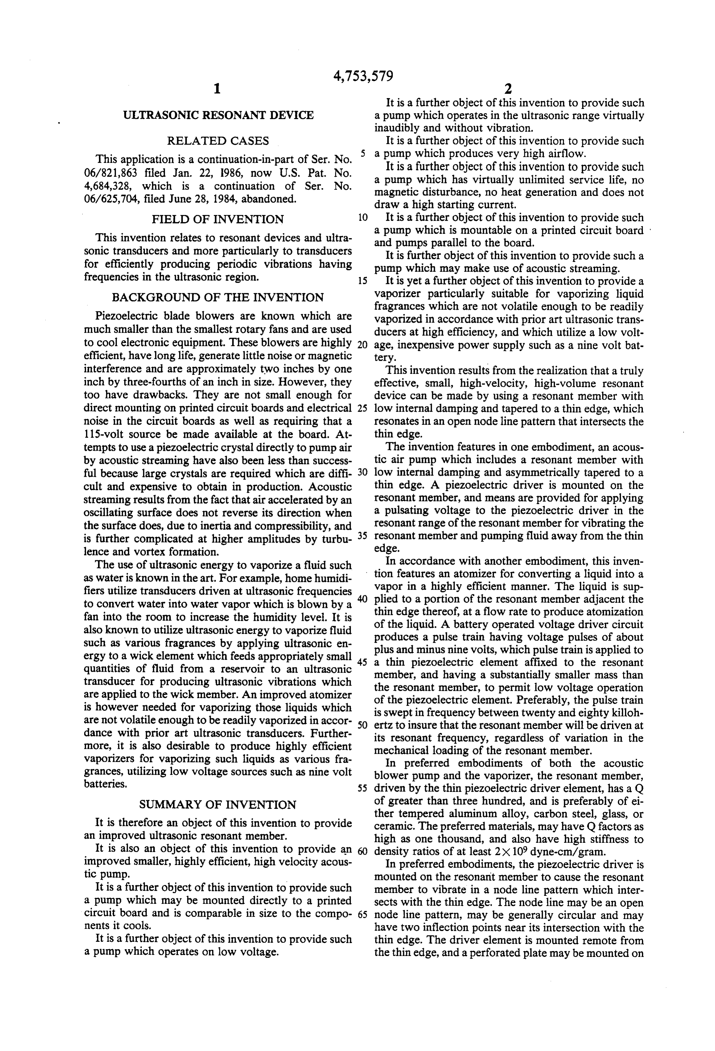
RELATED CASES It is a further object of this invention to provide such This application is a continuation-in-part of Ser. No. a pump which produces very high airflow. 06/821,863 filed Jan. 22, 1986, now U.S. Pat. No. It is a further object of this invention to provide such 4,684,328, which is a continuation of Ser. No. a pump which has virtually unlimited service life, no 06/625,704, filed June 28, 1984, abandoned. magnetic disturbance, no heat generation and does not draw a high starting current.
FIELD OF INVENTION 10 It is a further object of this invention to provide such This invention relates to resonant devices and ultra a pump which is mountable on a printed circuit board and pumps parallel to the board.
sonic transducers and more particularly to transducers It is further object of this invention to provide such a for efficiently producing periodic vibrations having pump which may make use of acoustic streaming. frequencies in the ultrasonic region. 15 It is yet a further object of this invention to provide a BACKGROUND OF THE INVENTION vaporizer particularly suitable for vaporizing liquid fragrances which are not volatile enough to be readily
Piezoelectric blade blowers are known which are vaporized in accordance with prior art ultrasonic trans much smaller than the smallest rotary fans and are used ducers at high efficiency, and which utilize a low volt to cool electronic equipment. These blowers are highly 20 age, inexpensive power supply such as a nine volt bat efficient, have long life, generate little noise or magnetic tery.
interference and are approximately two inches by one This invention results from the realization that a truly inch by three-fourths of an inch in size. However, they effective, small, high-velocity, high-volume resonant too have drawbacks. They are not small enough for device can be made by using a resonant member with direct mounting on printed circuit boards and electrical 25 low internal damping and tapered to a thin edge, which noise in the circuit boards as well as requiring that a resonates in an open node line pattern that intersects the 115-volt source be made available at the board. At thin edge.
tempts to use a piezoelectric crystal directly to pump air The invention features in one embodiment, an acous by acoustic streaming have also been less than success tic air pump which includes a resonant member with ful because large crystals are required which are diffi 30 low internal damping and asymmetrically tapered to a cult and expensive to obtain in production. Acoustic thin edge. A piezoelectric driver is mounted on the streaming results from the fact that air accelerated by an resonant member, and means are provided for applying oscillating surface does not reverse its direction when a pulsating voltage to the piezoelectric driver in the the surface does, due to inertia and compressibility, and 35 resonant range of the resonant member for vibrating the is further complicated at higher amplitudes by turbu resonant member and pumping fluid away from the thin lence and vortex formation. edge.
The use of ultrasonic energy to vaporize a fluid such In accordance with another embodiment, this inven as water is known in the art. For example, home humidi tion features an atomizer for converting a liquid into a vapor in a highly efficient manner. The liquid is sup fiers utilize transducers driven at ultrasonic frequencies plied to convert water into water vapor which is blown by a thin edge to a portion of the resonant member adjacent the fan into the room to increase the humidity level. It is of the liquid. thereof, at a flow rate to produce atomization also known to utilize ultrasonic energy to vaporize fluid produces a pulse A battery operated voltage driver circuit such as various fragrances by applying ultrasonic en plus and minus ninetrain having voltage pulses of about volts, which pulse train is applied to ergy to a wick element which feeds appropriately small 45 a thin piezoelectric element affixed to the resonant quantities of fluid from a reservoir to an ultrasonic transducer for producing ultrasonic vibrations which member, and having a substantially smaller mass than are applied to the wick member. An improved atomizer the resonant member, to permit low voltage operation is however needed for vaporizing those liquids which is sweptpiezoelectric of the element. Preferably, the pulse train are not volatile enough to be readily vaporized in accor 50 ertz to insure that the between in frequency twenty and eighty kiloh resonant member will be driven at dance with prior art ultrasonic transducers. Further its resonant frequency, regardless of variation in the more, it is also desirable to produce highly efficient mechanical loading of the resonant member. vaporizers for vaporizing such liquids as various fra In preferred embodiments of both the acoustic grances, utilizing low voltage sources such as nine volt blower pump and the vaporizer, the resonant member, batteries. 55 driven by the thin piezoelectric driver element, has a Q SUMMARY OF INVENTION of greater than three hundred, and is preferably of ei ther tempered aluminum alloy, carbon steel, glass, or
It is therefore an object of this invention to provide ceramic. The preferred materials, may have Q factors as an improved ultrasonic resonant member. high as one thousand, and also have high stiffness to It is also an object of this invention to provide an density ratios of at least 2X 10⁹ dyne-cm/gram. improved smaller, highly efficient, high velocity acous In preferred embodiments, the piezoelectric driver is tic pump. mounted on the resonant member to cause the resonant It is a further object of this invention to provide such member to vibrate in a node line pattern which inter a pump which may be mounted directly to a printed sects with the thin edge. The node line may be an open circuit board and is comparable in size to the compo 65 node line pattern, may be generally circular and may nents it cools. have two inflection points near its intersection with the It is a further object of this invention to provide such thin edge. The driver element is mounted remote from a pump which operates on low voltage. the thin edge, and a perforated plate may be mounted on
Page 6
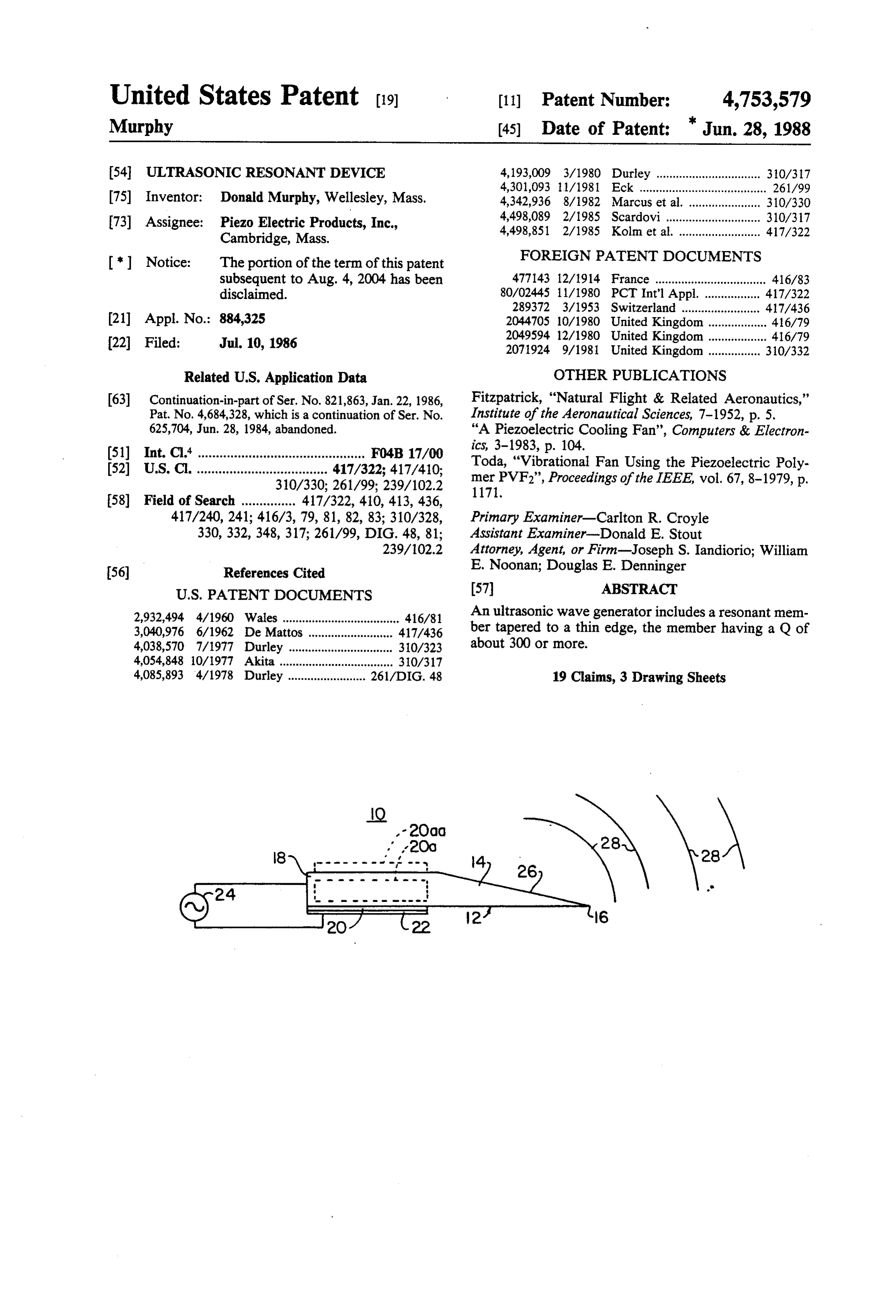
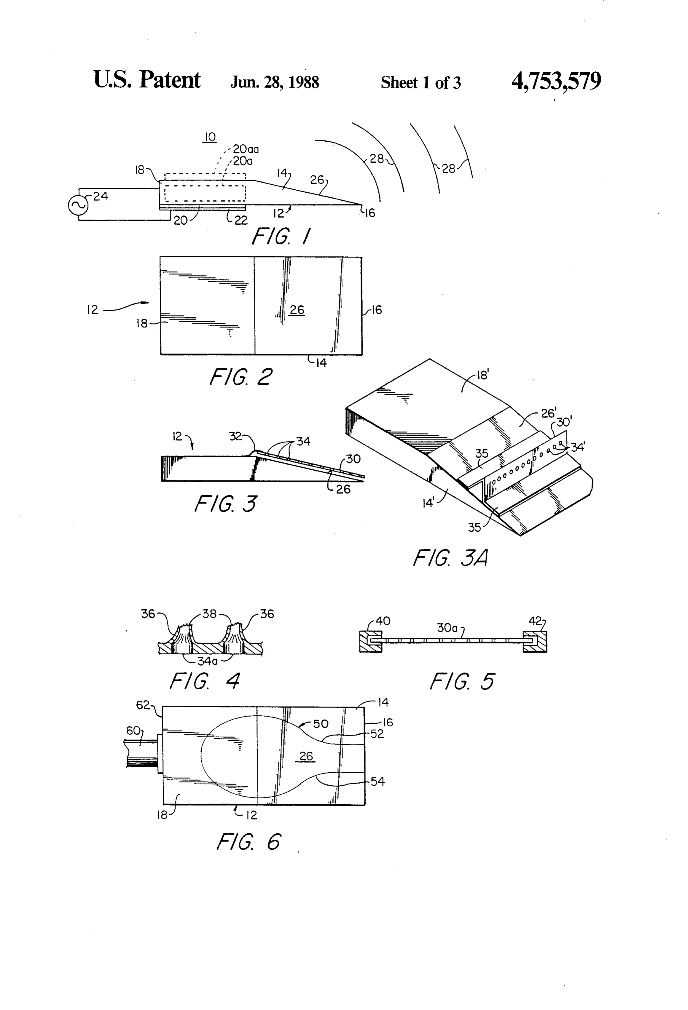
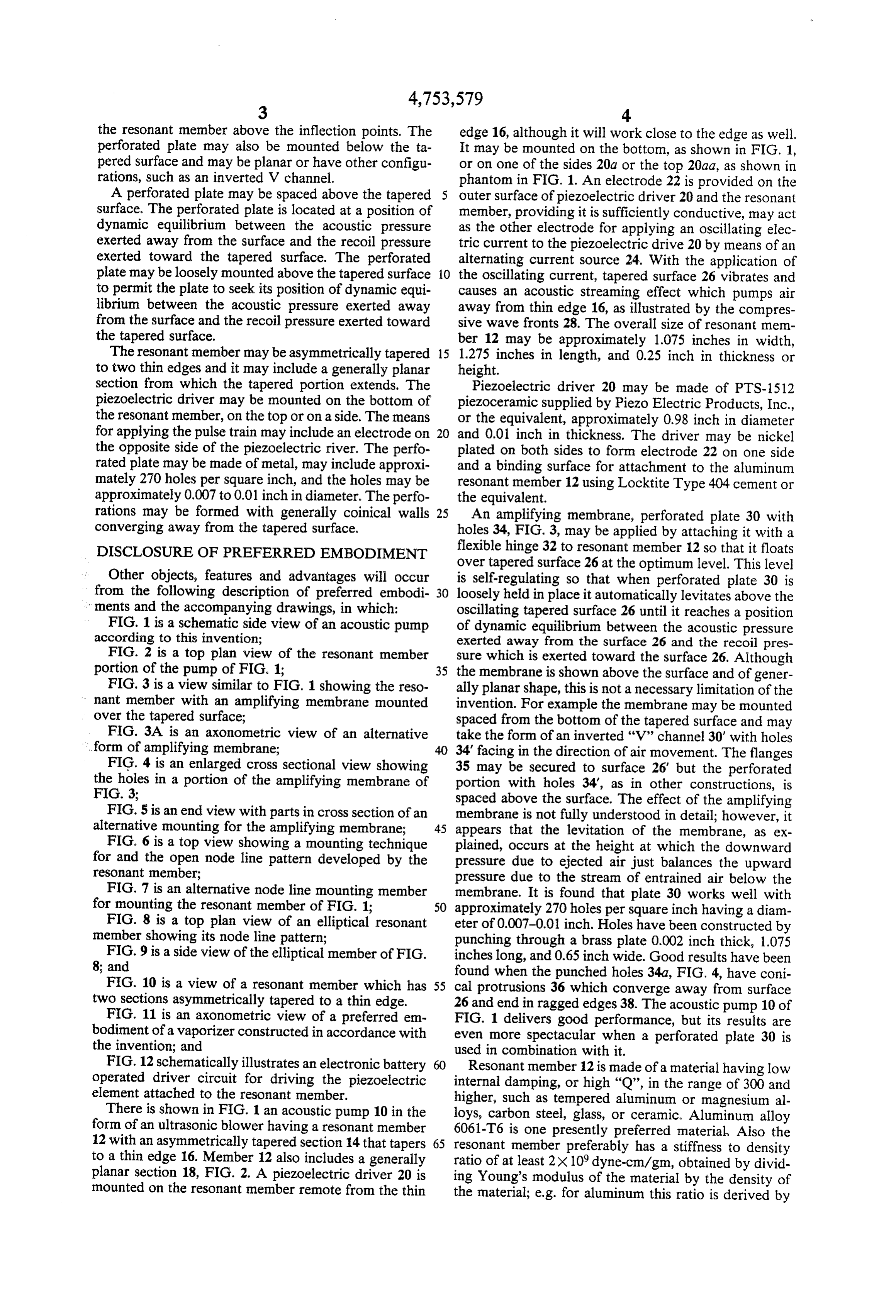
the resonant member above the inflection points. The edge 16, although it will work close to the edge as well. perforated plate may also be mounted below the ta It may be mounted on the bottom, as shown in FIG. 1, pered surface and may be planar or have other configu or on one of the sides 20a or the top 20aa, as shown in rations, such as an inverted V channel. phantom in FIG. 1. An electrode 22 is provided on the A perforated plate may be spaced above the tapered 5 outer surface of piezoelectric driver 20 and the resonant surface. The perforated plate is located at a position of member, providing it is sufficiently conductive, may act dynamic equilibrium between the acoustic pressure as the other electrode for applying an oscillating elec exerted away from the surface and the recoil pressure tric current to the piezoelectric drive 20 by means of an exerted toward the tapered surface. The perforated alternating current source 24. With the application of plate may be loosely mounted above the tapered surface O the oscillating current, tapered surface 26 vibrates and to permit the plate to seek its position of dynamic equi causes an acoustic streaming effect which pumps air librium between the acoustic pressure exerted away away from thin edge 16, as illustrated by the compres from the surface and the recoil pressure exerted toward sive wave fronts 28. The overall size of resonant mem the tapered surface. ber 12 may be approximately 1.075 inches in width, The resonant member may be asymmetrically tapered 15 1.275 inches in length, and 0.25 inch in thickness or to two thin edges and it may include a generally planar height.
section from which the tapered portion extends. The Piezoelectric driver 20 may be made of PTS-1512 piezoelectric driver may be mounted on the bottom of piezoceramic supplied by Piezo Electric Products, Inc., the resonant member, on the top or on a side. The means or the equivalent, approximately 0.98 inch in diameter for applying the pulse train may include an electrode on and 0.01 inch in thickness. The driver may be nickel the opposite side of the piezoelectric river. The perfo plated on both sides to form electrode 22 on one side rated plate may be made of metal, may include approxi and a binding surface for attachment to the aluminum mately 270 holes per square inch, and the holes may be resonant member 12 using Locktite Type 404 cement or approximately 0.007 to 0.01 inch in diameter. The perfo the equivalent.
rations may be formed with generally coinical walls 25 An amplifying membrane, perforated plate 30 with converging away from the tapered surface. holes 34, FIG. 3, may be applied by attaching it with a DISCLOSURE OF PREFERRED EMBODIMENT flexible hinge 32 to resonant member 12 so that it floats over tapered surface 26 at the optimum level. This level
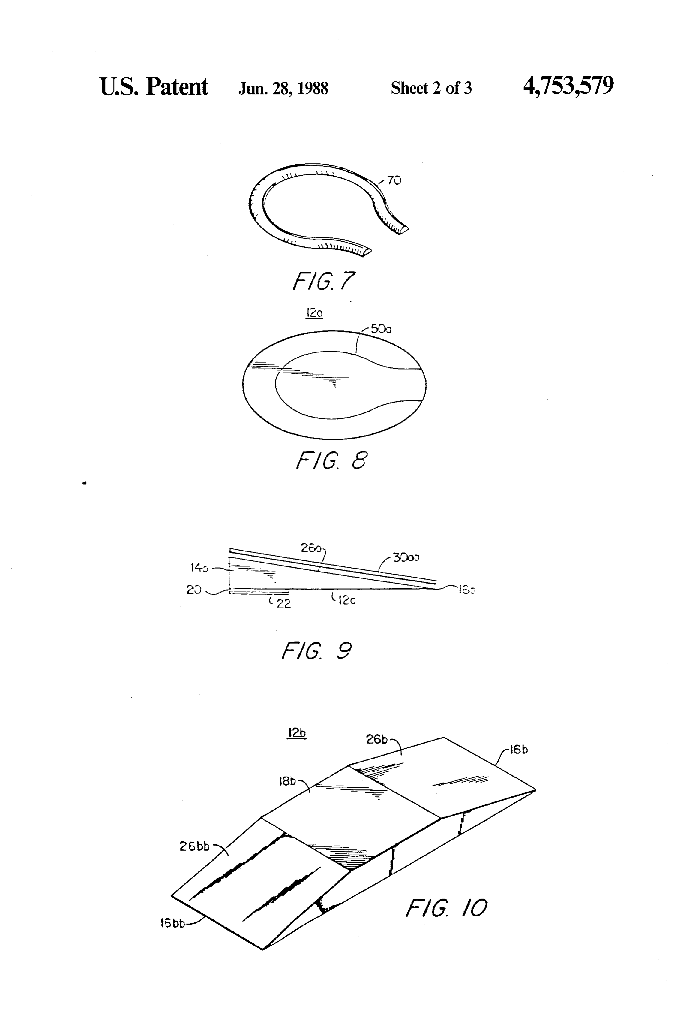
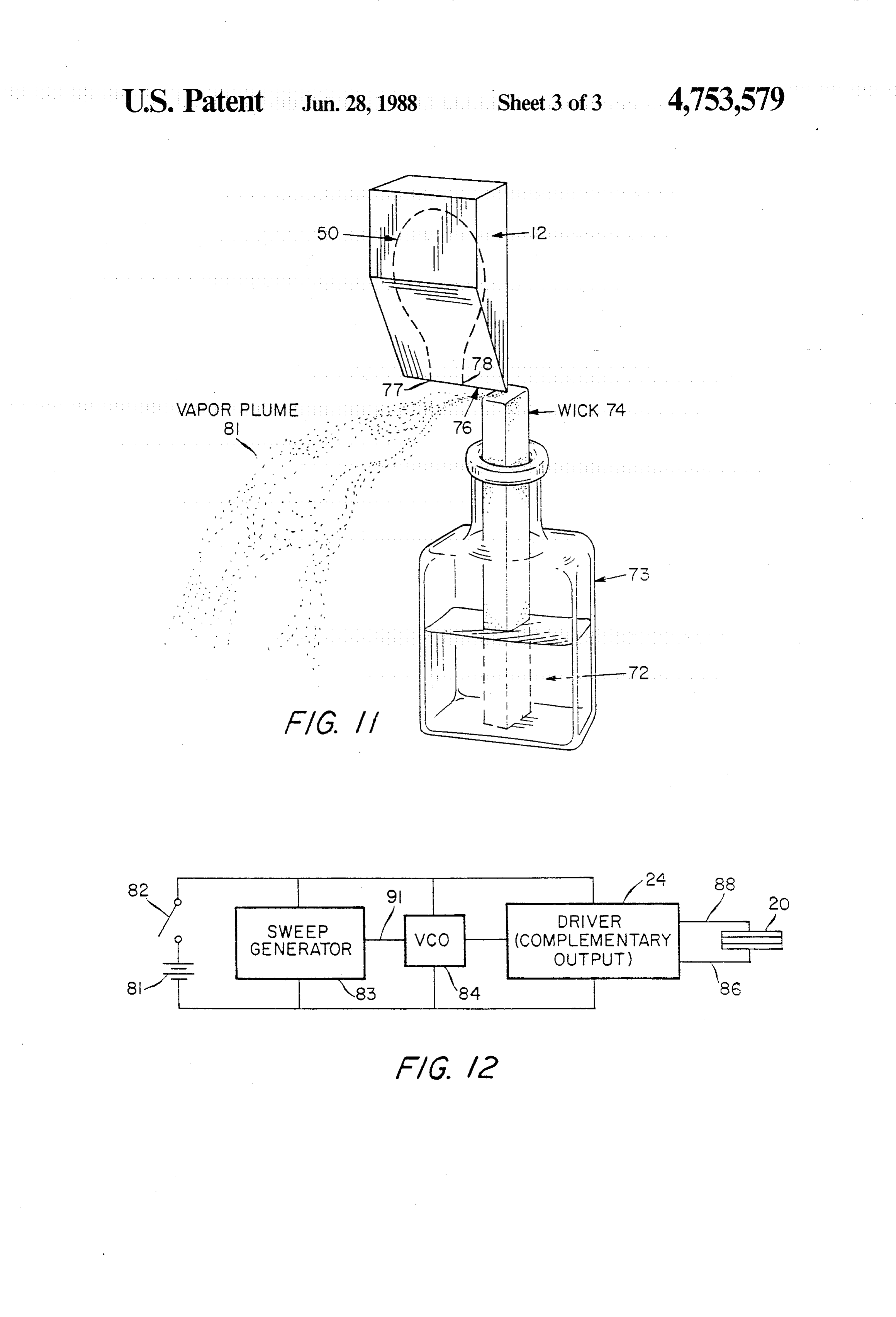
Other objects, features and advantages will occur is self-regulating so that when perforated plate 30 is from the following description of preferred embodi 30 loosely held in place it automatically levitates above the ments and the accompanying drawings, in which: oscillating tapered surface 26 until it reaches a position FIG. 1 is a schematic side view of an acoustic pump of dynamic equilibrium between the acoustic pressure according to this invention; exerted away from the surface 26 and the recoil pres FIG. 2 is a top plan view of the resonant member sure which is exerted toward the surface 26. Although portion of the pump of FIG. 1; 35 the membrane is shown above the surface and of gener FIG. 3 is a view similar to FIG. 1 showing the reso ally planar shape, this is not a necessary limitation of the nant member with an amplifying membrane mounted invention. For example the membrane may be mounted over the tapered surface; spaced from the bottom of the tapered surface and may FIG. 3A is an axonometric view of an alternative take the form of an inverted 'V' channel 30' with holes ... form of amplifying membrane; 40 34 facing in the direction of air movement. The flanges FIG. 4 is an enlarged cross sectional view showing 35 may be secured to surface 26' but the perforated the holes in a portion of the amplifying membrane of portion with holes 34, as in other constructions, is FIG. 3; spaced above the surface. The effect of the amplifying FIG. 5 is an end view with parts in cross section of an membrane is not fully understood in detail; however, it alternative mounting for the amplifying membrane; 45 appears that the levitation of the membrane, as ex FIG. 6 is a top view showing a mounting technique plained, occurs at the height at which the downward for and the open node line pattern developed by the pressure due to ejected air just balances the upward resonant member; pressure due to the stream of entrained air below the FIG. 7 is an alternative node line mounting member membrane. It is found that plate 30 works well with for mounting the resonant member of FIG. 1; 50 approximately 270 holes per square inch having a diam FIG. 8 is a top plan view of an elliptical resonant eter of 0.007-0.01 inch. Holes have been constructed by member showing its node line pattern; punching through a brass plate 0.002 inch thick, 1.075 FIG. 9 is a side view of the elliptical member of FIG. inches long, and 0.65 inch wide. Good results have been 8; and found when the punched holes 34a, FIG. 4, have coni FIG. 10 is a view of a resonant member which has 55 cal protrusions 36 which converge away from surface two sections asymmetrically tapered to a thin edge. 26 and end in ragged edges 38. The acoustic pump 10 of FIG. 11 is an axonometric view of a preferred em FIG. 1 delivers good performance, but its results are bodiment of a vaporizer constructed in accordance with even more spectacular when a perforated plate 30 is the invention; and used in combination with it. FIG. 12 schematically illustrates an electronic battery Resonant member 12 is made of a material having low operated driver circuit for driving the piezoelectric internal damping, or high 'Q', in the range of 300 and element attached to the resonant member. higher, such as tempered aluminum or magnesium al There is shown in FIG. 1 an acoustic pump 10 in the loys, carbon steel, glass, or ceramic. Aluminum alloy form of an ultrasonic blower having a resonant member 6061-T6 is one presently preferred material. Also the 12 with an asymmetrically tapered section 14 that tapers 65 resonant member preferably has a stiffness to density to a thin edge 16. Member 12 also includes a generally ratio of at least 2X 10⁹ dyne-cm/gm, obtained by divid planar section 18, FIG. 2. A piezoelectric driver 20 is ing Young's modulus of the material by the density of mounted on the resonant member remote from the thin the material; e.g. for aluminum this ratio is derived by
Page 7
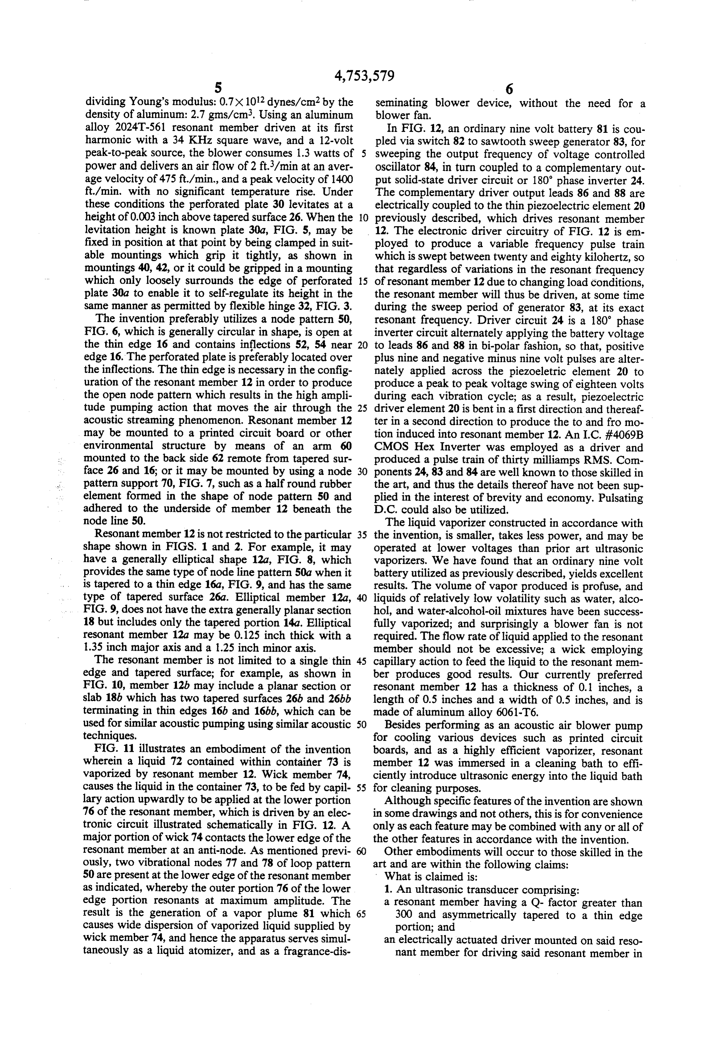
dividing Young's modulus: 0.7x10² dynes/cm2 by the seminating blower device, without the need for a density of aluminum: 2.7gms/cm. Using an aluminum blower fan.
alloy 2024T-561 resonant member driven at its first In FIG. 12, an ordinary nine volt battery 81 is cou harmonic with a 34 KHz square wave, and a 12-volt pled via switch 82 to sawtooth sweep generator 83, for peak-to-peak source, the blower consumes 1.3 watts of 5 sweeping the output frequency of voltage controlled power and delivers an air flow of 2 ft./min at an aver oscillator 84, in turn coupled to a complementary out age velocity of 475 ft/min, and a peak velocity of 1400 put solid-state driver circuit or 180° phase inverter 24. ft/min, with no significant temperature rise. Under The complementary driver output leads 86 and 88 are these conditions the perforated plate 30 levitates at a electrically coupled to the thin piezoelectric element 20 height of 0.003 inch above tapered surface 26. When the O previously described, which drives resonant member levitation height is known plate 30a, FIG. 5, may be 12. The electronic driver circuitry of FIG. 12 is em fixed in position at that point by being clamped in suit ployed to produce a variable frequency pulse train able mountings which grip it tightly, as shown in which is swept between twenty and eighty kilohertz, so mountings 40, 42, or it could be gripped in a mounting that regardless of variations in the resonant frequency which only loosely surrounds the edge of perforated 15 of resonant member 12 due to changing load conditions, plate 30a to enable it to self-regulate its height in the the resonant member will thus be driven, at some time same manner as permitted by flexible hinge 32, FIG. 3. during the sweep period of generator 83, at its exact The invention preferably utilizes a node pattern 50, resonant frequency. Driver circuit 24 is a 180° phase FIG. 6, which is generally circular in shape, is open at inverter circuit alternately applying the battery voltage the thin edge 16 and contains inflections 52, 54 near 20 to leads 86 and 88 in bi-polar fashion, so that, positive edge 16. The perforated plate is preferably located over plus nine and negative minus nine volt pulses are alter the inflections. The thin edge is necessary in the config nately applied across the piezoeletric element 20 to uration of the resonant member 12 in order to produce produce a peak to peak voltage swing of eighteen volts the open node pattern which results in the high ampli during each vibration cycle; as a result, piezoelectric tude pumping action that moves the air through the 25 driver element 20 is bent in a first direction and thereaf acoustic streaming phenomenon. Resonant member 12 ter in a second direction to produce the to and fromo may be mounted to a printed circuit board or other tion induced into resonant member 12. An I.C. #4069B environmental structure by means of an arm 60 CMOS Hex Inverter was employed as a driver and mounted to the back side 62 remote from tapered sur produced a pulse train of thirty milliamps RMS. Com face 26 and 16; or it may be mounted by using a node 30 ponents 24, 83 and 84 are well known to those skilled in pattern support 70, FIG. 7, such as a half round rubber the art, and thus the details thereof have not been sup element formed in the shape of node pattern 50 and plied in the interest of brevity and economy. Pulsating adhered to the underside of member 12 beneath the D.C. could also be utilized. node line 50. The liquid vaporizer constructed in accordance with Resonant member 12 is not restricted to the particular 35 the invention, is smaller, takes less power, and may be shape shown in FIGS. 1 and 2. For example, it may operated at lower voltages than prior art ultrasonic have a generally elliptical shape 12a, FIG. 8, which vaporizers. We have found that an ordinary nine volt provides the same type of node line pattern 50a when it battery utilized as previously described, yields excellent is tapered to a thin edge 16a, FIG. 9, and has the same results. The volume of vapor produced is profuse, and type of tapered surface 26a. Elliptical member 12a, liquids of relatively low volatility such as water, alco FIG. 9, does not have the extra generally planar section hol, and water-alcohol-oil mixtures have been success 18 but includes only the tapered portion 14a. Elliptical fully vaporized; and surprisingly a blower fan is not resonant member 12a may be 0.125 inch thick with a required. The flow rate of liquid applied to the resonant 1.35 inch major axis and a 1.25 inch minor axis. member should not be excessive; a wick employing The resonant member is not limited to a single thin 45 capillary action to feed the liquid to the resonant mem edge and tapered surface; for example, as shown in ber produces good results. Our currently preferred FIG. 10, member 12b may include a planar section or resonant member 12 has a thickness of 0.1 inches, a slab 18b which has two tapered surfaces 26b and 26bb length of 0.5 inches and a width of 0.5 inches, and is terminating in thin edges 16b and 16bb, which can be made of aluminum alloy 6061-T6.
used for similar acoustic pumping using similar acoustic 50 Besides performing as an acoustic air blower pump techniques. for cooling various devices such as printed circuit FIG. 11 illustrates an embodiment of the invention boards, and as a highly efficient vaporizer, resonant wherein a liquid 72 contained within container 73 is member 12 was immersed in a cleaning bath to effi vaporized by resonant member 12. Wick member 74, ciently introduce ultrasonic energy into the liquid bath causes the liquid in the container 73, to be fed by capil 55 for cleaning purposes.
lary action upwardly to be applied at the lower portion Although specific features of the invention are shown 76 of the resonant member, which is driven by an elec in some drawings and not others, this is for convenience tronic circuit illustrated schematically in FIG. 12. A only as each feature may be combined with any or all of major portion of wick 74 contacts the lower edge of the the other features in accordance with the invention. resonant member at an anti-node. As mentioned previ Other embodiments will occur to those skilled in the ously, two vibrational nodes 77 and 78 of loop pattern art and are within the following claims: 50 are present at the lower edge of the resonant member What is claimed is:
as indicated, whereby the outer portion 76 of the lower 1. An ultrasonic transducer comprising: edge portion resonants at maximum amplitude. The a resonant member having a Q- factor greater than result is the generation of a vapor plume 81 which 65 300 and asymmetrically tapered to a thin edge causes wide dispersion of vaporized liquid supplied by portion; and wick member 74, and hence the apparatus serves simul an electrically actuated driver mounted on said reso taneously as a liquid atomizer, and as a fragrance-dis nant member for driving said resonant member in
Page 8
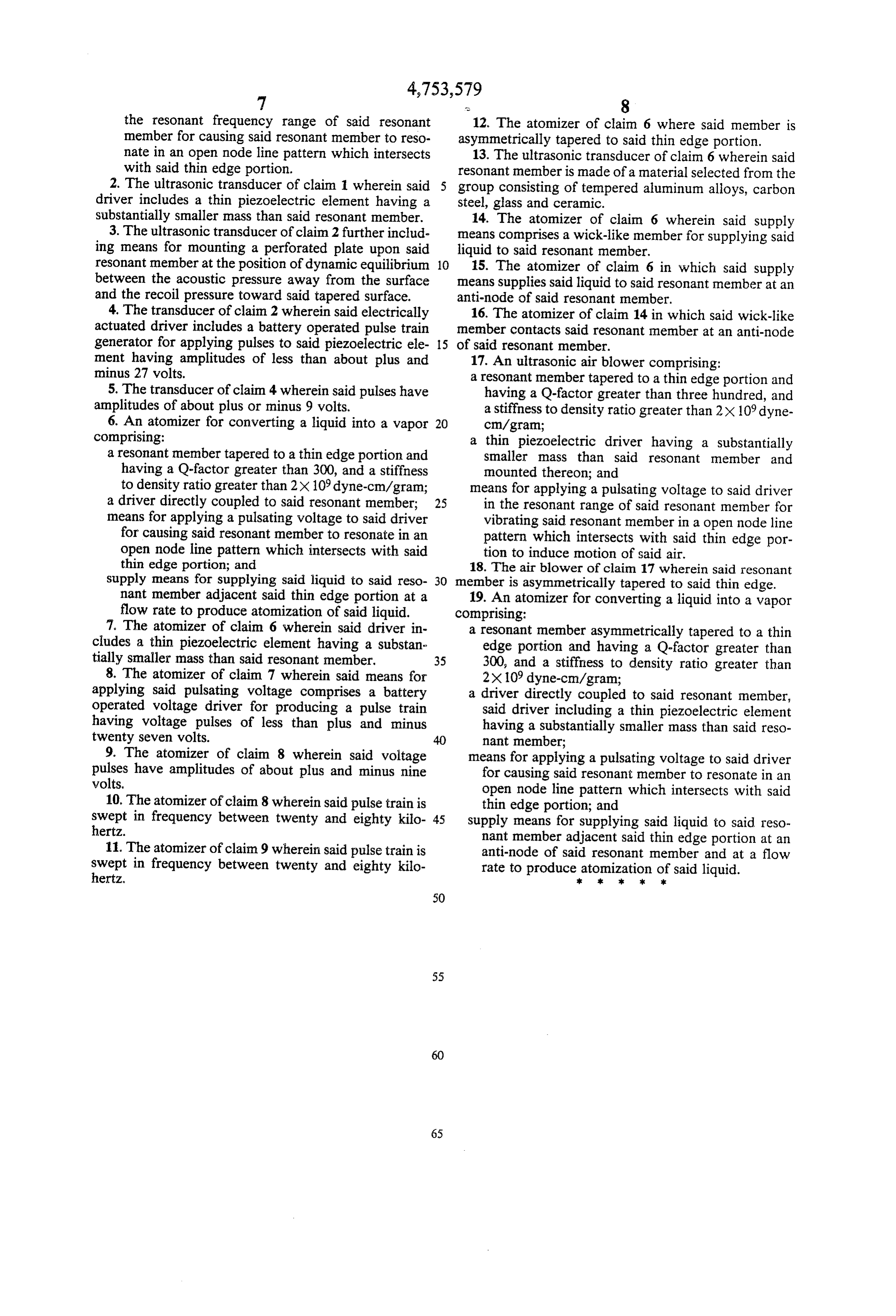
the resonant frequency range of said resonant 12. The atomizer of claim 6 where said member is member for causing said resonant member to reso asymmetrically tapered to said thin edge portion. nate in an open node line pattern which intersects 13. The ultrasonic transducer of claim 6 wherein said with said thin edge portion. resonant member is made of a material selected from the 2. The ultrasonic transducer of claim 1 wherein said group consisting of tempered aluminum alloys, carbon driver includes a thin piezoelectric element having a steel, glass and ceramic.
substantially smaller mass than said resonant member. 14. The atomizer of claim 6 wherein said supply 3. The ultrasonic transducer of claim 2 further includ means comprises a wick-like member for supplying said ing means for mounting a perforated plate upon said liquid to said resonant member.
resonant member at the position of dynamic equilibrium 10 15. The atomizer of claim 6 in which said supply between the acoustic pressure away from the surface means supplies said liquid to said resonant member at an and the recoil pressure toward said tapered surface. anti-node of said resonant member. 4. The transducer of claim 2 wherein said electrically 16. The atomizer of claim 14 in which said wick-like actuated driver includes a battery operated pulse train member contacts said resonant member at an anti-node generator for applying pulses to said piezoelectric ele 15 of said resonant member.
ment having amplitudes of less than about plus and 17. An ultrasonic air blower comprising: minus 27 volts. a resonant member tapered to a thin edge portion and 5. The transducer of claim 4 wherein said pulses have having a Q-factor greater than three hundred, and amplitudes of about plus or minus 9 volts. a stiffness to density ratio greater than 2x 10⁹ dyne 6. An atomizer for converting a liquid into a vapor 20 cm/gram;
comprising: a thin piezoelectric driver having a substantially a resonant member tapered to a thin edge portion and smaller mass than said resonant member and having a Q-factor greater than 300, and a stiffness mounted thereon; and to density ratio greater than 2x 10⁹ dyne-cm/gram; means for applying a pulsating voltage to said driver a driver directly coupled to said resonant member; 25 in the resonant range of said resonant member for means for applying a pulsating voltage to said driver vibrating said resonant member in a open node line for causing said resonant member to resonate in an pattern which intersects with said thin edge por open node line pattern which intersects with said tion to induce motion of said air. thin edge portion; and 18. The air blower of claim 17 wherein said resonant supply means for supplying said liquid to said reso 30 member is asymmetrically tapered to said thin edge. nant member adjacent said thin edge portion at a 19. An atomizer for converting a liquid into a vapor flow rate to produce atomization of said liquid. comprising:
7. The atomizer of claim 6 wherein said driver in a resonant member asymmetrically tapered to a thin cludes a thin piezoelectric element having a substan edge portion and having a Q-factor greater than tially smaller mass than said resonant member. 35 300, and a stiffness to density ratio greater than 8. The atomizer of claim 7 wherein said means for 2x 10⁹ dyne-cm/gram;
applying said pulsating voltage comprises a battery a driver directly coupled to said resonant member, operated voltage driver for producing a pulse train said driver including a thin piezoelectric element having voltage pulses of less than plus and minus having a substantially smaller mass than said reso twenty seven volts. nant member;
9. The atomizer of claim 8 wherein said voltage means for applying a pulsating voltage to said driver pulses have amplitudes of about plus and minus nine for causing said resonant member to resonate in an volts. open node line pattern which intersects with said 10. The atomizer of claim 8 wherein said pulse train is thin edge portion; and swept in frequency between twenty and eighty kilo 45 supply means for supplying said liquid to said reso hertz. nant member adjacent said thin edge portion at an 11. The atomizer of claim 9 wherein said pulse train is anti-node of said resonant member and at a flow swept in frequency between twenty and eighty kilo rate to producexatomization ofx said liquid. hertz. k is k
Provenance
- Collection
- Cited prior art
- Original PDF
- patentimages.storage.googleapis.com →
- Filed
- 1986-07-10
- Pages
- 8
- Method
- pdftotext (the PDF's own text layer) + pdftoppm 300dpi page scans
- Source
- Google Patents bibliographic record
- Granted
- 1988-06-28
- Inventors
- Donald Murphy; Piezo Electric Products Inc
- Transcribed from
- patentimages.storage.googleapis.com →