patent · US5343699
Method and apparatus for improved operation of internal combustion engines
6 September 1994
Page 1 — bibliographic record
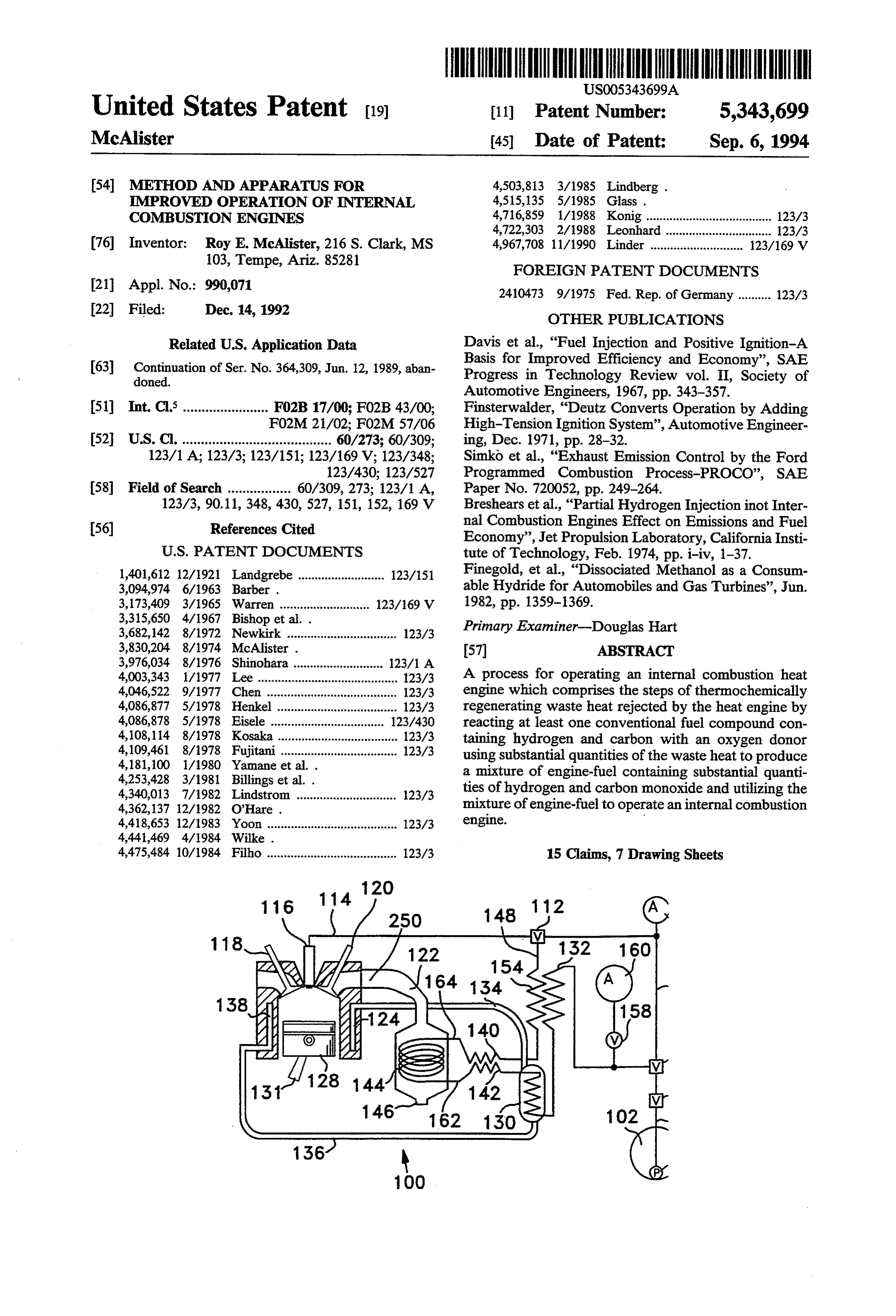
United States Patent 19 11 Patent Number: 5,343,699 McAlister 45 Date of Patent: Sep. 6, 1994 54 METHOD AND APPARATUS FOR 4,503,813 3/1985 Lindberg . MPROVED OPERATION OF INTERNAL 4,515,135 5/1985 Glass . COMBUSTON ENGINES 4,716,859 1/1988 Konig ...................................... 123/3 4,722,303 2/1988 Leonhard ................................ 123/3 76 Inventor: Roy E. McAlister, 216 S. Clark, MS 4,967,708 11/1990 Linder ............................ 123/169 V 103, Tempe, Ariz. 85281 FOREIGN PATENT DOCUMENTS 21 Appl. No.: 990,071 2410473 9/1975 Fed. Rep. of Germany .......... 123/3 22 Filed: Dec. 14, 1992 OTHER PUBLICATIONS Related U.S. Application Data Davis et al., "Fuel Injection and Positive Ignition-A 63 Continuation of Ser. No. 364,309, Jun. 12, 1989, aban Basis for Improved Efficiency and Economy', SAE doned. Progress in Technology Review vol. II, Society of Automotive Engineers, 1967, pp. 343–357.
51 Int. Cl........................ FO2B 17/00; FO2B 43/00; Finsterwalder, “Deutz Converts Operation by Adding F02M 21/02; FO2M 57/06 High-Tension Ignition System', Automotive Engineer 52 U.S. C. ........................................ 60/273; 60/309; ing, Dec. 1971, pp. 28-32. 123/1 A; 123/3; 123/151; 123/169 V; 123/348; Simko et al., "Exhaust Emission Control by the Ford 123/430; 123/527 Programmed Combustion Process-PROCO', SAE 58 Field of Search ................. 60/309, 273; 123/1 A, Paper No. 720052, pp. 249-264. 123/3, 90.11, 348, 430,527, 151, 152, 169 V Breshears et al., "Partial Hydrogen Injection inot Inter 56) References Cited nal Combustion Engines Effect on Emissions and Fuel Economy', Jet Propulsion Laboratory, California Insti
1,401,612 12/1921 Landgrebe .......................... 123/151 Finegold, et al., “Dissociated Methanol as a Consum 3,094,974 6/1963 Barber . able Hydride for Automobiles and Gas Turbines', Jun. 3,173,409 3/1965 Warren ........................... 123/169 V 1982, pp. 1359-1369.
3,315,650 4/1967 Bishop et al. . Primary Examiner-Douglas Hart 3,682,142 8/1972 Newkirk ................................. 123/3 3,830,204 8/1974 McAlister . 57 ABSTRACT 3,976,034 8/1976 Shinohara ........................... 123/1 A 4,003,343 1/1977 Lee .......................................... 123/3 A process for operating an internal combustion heat 4,046,522 9/1977 Chen ....................................... 123/3 engine which comprises the steps of thermochemically 4,086,877 5/1978 Henkel .................................... 123/3 regenerating waste heat rejected by the heat engine by 4,086,878 5/1978 Eisele ..... - - -- - - - - - -- - -- - - - - 123/430 reacting at least one conventional fuel compound con 4,108,114 8/1978 Kosaka .................................... 123/3 taining hydrogen and carbon with an oxygen donor 4,109,461 8/1978 Fujitani ................................... 123/3 using substantial quantities of the waste heat to produce 4,181,100 1/1980 Yamane et al. . a mixture of engine-fuel containing substantial quanti 4,253,428 3/1981 Billings et al. . ties of hydrogen and carbon monoxide and utilizing the 4,340,013 7/1982 Lindstrom .............................. 1.23/3 4,362,137 12/1982 O'Hare . mixture of engine-fuel to operate an internal combustion 4,418,653 12/1983 Yoon ....................................... 123/3 engine.
4,475,484 10/1984 Filho ....................................... 123/3 15 Claims, 7 Drawing Sheets
Page 2
Drawing sheet — no readable text.
Page 3
Drawing sheet — no readable text.
Page 4
Drawing sheet — no readable text.
Page 5
Drawing sheet — no readable text.
Page 6
Drawing sheet — no readable text.
Page 7
Drawing sheet — no readable text.
Page 8
Drawing sheet — no readable text.
Page 9
sprayed into the compressed air. Such technology re
METHOD AND APPARATUS FOR IMPROVED quires fuels with specific characteristics that facilitate OPERATION OF INTERNAL COMBUSTION "compression ignition'. Fuels suitable for compression ENGINES ignition engines have high "cetane' ratings. Direct 5 injection compression engines often obtain about two
This is a continuation of application Ser. No. times higher miles per fuel-BTU ratings than homo 07/364,309, filed Jun. 12, 1989, now abandoned. geneous-charge engines in practical duty cycles because This invention relates to improved operation of inter of stratified charge advantages of more complete com nal combustion engines. bustion and reduced heat losses from combustion prod 10 ucts to engine components.
BACKGROUND OF THE INVENTION
There is about one motor vehicle for every eleven engine A substantial problem with the compression ignition persons on earth. Some 400 million cars and trucks are requiringis the engine weight penalty that stems from about two times more displacement than operated throughout the world. The bulk of these vehi spark ignited engines cles operate in North America and Western Europe. 15 tion, this translates to aofmuch equal power ratings. In opera larger crankshaft, a larger
Over 40% of the world's vehicles, about 176 million flywheel, a larger engine block, larger bearings, larger cars and trucks are operated in the United States. starter
Homogeneous-charge engines power the vast majority heavier motors, heavier-duty batteries, larger tires, springs, bigger shock absorbers, and a much of motor vehicles. In these engines it is attempted to larger requirement for critical alloying resources such develop a homogeneous mixture of air and fuel vapor 20 by fuel injection or carburation into an intake manifold as molybdenum, chromium, vanadium, copper, nickel, for delivery to the engine's combustion chambers. tin, lead, antimony, and content of manufacturing en Homogeneous-charge engines present numerous prob ergy to mine, refine, cast, heat treat and machine than lems including: spark-ignited engines. Other difficult if not unaccept 1. Unburned hydrocarbons and carbon monoxide 25 able problems include:
emissions are unacceptable from homogeneous-charge 1. Diesel engines are notorious for belching clouds of engines. These emissions are caused by quenching of black smoke during stop and go duty cycles. Bus and homogeneous-charge combustion processes near com truck emissions of nauseous, burned-oil smelling, black bustion-chamber walls. All major cities are polluted by smoke in city traffic are unacceptable in view of recent carbon monoxide and unburned hydrocarbons from 30 efforts by virtually every city of the world to reduce homogeneous-charge engines. atmospheric pollution from motor vehicles. 2. Another cause of unburned hydrocarbons and 2. Diesel engines are extremely difficult to convert to carbon monoxide from homogeneous-charge engines is oxygenated fuels (CH3OH, C2H5OH, etc.) or other operation at insufficient air to fuel ratios to complete clean burning fuels (such as natural gas and hydrogen) combustion processes at the relatively high piston 35 because such preferred fuels have high octane ratings speeds of modern cars. It is a widespread practice to and low cetane ratings. Diesel engines require a high operate the engine at air-fuel ratios for best power pro cetane rated pilot fuel (Diesel fuel) to torch-ignite clean duction in spite of the fact that operation at excess-air burning fuels that are "fumigated' into the combustion conditions would produce less unburned hydrocarbons chamber along with air supplies during intake cycle and carbon-monoxide emissions. operations.
3. Oxides of nitrogen emissions are unacceptable from 3. Fumigation of fuels into the combustion chamber homogeneous-charge engines. Increasing the air to fuel along with air during the intake cycle derates the engine ratio as in homogeneous-charge "lean burn' operations because the fumigated fuel uses part of the breathing increases production of oxides of nitrogen. capacity and reduces effective volumetric efficiency of 4. Several catalytic processes and an auxiliary air 45 the converted engine.
supply are needed to clean-up the exhaust streams of 4. Compression ignition engines are hard to start in homogeneous-charge engines. Modern cars operating at cold weather. Cold air and cold engine components rob air-fuel ratios optimized for driveability and minimal the heat of compression before temperatures are oxides of nitrogen require addition of air to the exhaust reached that will cause fuel to be evaporated, chemi stream for purposes of catalytic combustion of un 50 cally cracked, and ignited. Expensive subsystems such burned hydrocarbons and carbon monoxide. as spark-ignited starter engines, glow plugs, electric 5. Unacceptable energy waste occurs as a great per block heaters, and starter fluid dispensers are used in centage of the fuel present in a homogeneous charge attempts to overcome the difficulties of starting com burns near combustion chamber surfaces. Heat is trans pression-ignition engines in cold weather. Frequently ferred to metallic components including the head, 55 owners of vehicles with compression-ignition engines valves, cylinder liner, piston and rings without doing opt to keep the engine running day and night in the cold useful work. season at whatever fuel expense is incurred rather un 6. Homogeneous-charge engines must be limited in dergo the ordeal of trying to start a Diesel engine in compression ratio to values that prevent detonating cold weather.
ignition and piston damage. Positive ignition is 5. Compression-ignition engines operate best in a achieved by spark plugs. narrow range of torque-speed conditions. This is be Technology which has been accepted for improving cause of the characteristic called Diesel-ignition delay the thermal efficiency of internal combustion engines and the requirement to tailor the amount of fuel intro includes the venerable Diesel engine apparatus and duced and timing of fuel introduction with respect to method of direct injection of fuel into the combustion 65 the piston speed in order to avoid needless if not chamber. This technology is characterized as compress damaging pressure rise during the compression cycle ing air to produce sufficiently high temperatures to and to avoid energy waste and smoke from late burning evaporate, chemically crack, and ignite fuel that is during the power cycle.
Page 10
6. Compression-ignition engines require the use of 2. Fuel directed towards the spark source from the high cetane fuels with carbon to hydrogen mass ratios fuel injector for purposes of producing a suitable mix of about 7. Such fuels and their products of combustion ture of fuel and air for spark ignition invariably reach have large radiant energy losses to combustion chamber metallic heat-robbing areas of the combustion chamber walls during burning processes. It would greatly im around the spark source. This results in combustion prove thermal efficiency to use cleaner burning fuels process quenching and heat losses through components that have lower carbon to hydrogen mass ratios and of the combustion chamber.
much lower radiant energy losses but such fuels cannot 3. Spark sources such as spark plugs are prone to fail be compression ignited in conventional engines. because of oxidation and excessive heating due to the 7. Friction losses are larger in longer stroked, higher 10 location they are placed as a result of efforts to place the compression, and larger bearing area Diesel engines spark gap as far into the combustion chamber as possi than in spark-ignited engines of the same power rating. ble.
In addition to robbing potential power this requires 4. Spark sources are also prone to become soot coated more investment in expensive alloys, case hardening, during portions of the duty cycle and subsequently fail heat treatment and wear reducing design considerations 15 to deliver adequate plasma energy for assured ignition. than required for spark-ignition engines. 5. Widely varying emissions such as soot at some Technology for combining the advantages of spark speeds and excessive oxides of nitrogen at other speeds ignition and stratified charge burning have been demon characterize operation at essential portions of the stop strated. U.S. Pat. Nos. 3,830,204; 3,094,974 and and-go, city-driving duty cycle such as low-speed ac 3,316,650 and the references cited therein disclose meth 20 celeration, transient conditions and full power. ods and apparatus for introducing fuel directly into the 6. Efforts to overcome the problems arising from combustion chamber to form a stratified charge mixture undesirable fuel-air ratios at the spark source during of spark-ignitable fuel and ignition of such stratified important portions of the duty cycle have resulted in charges by a spark source. Other published references efficiency sacrificing practices of air throttling. include "Fuel Injection and Positive Ignition-A Basis 25 (See "Exhaust Emission Control. By the Ford Pro For Improved Efficiency and Economy, Burning a grammed Combustion Process: PROCO', by Simko, Wide Range of Fuels in Diesel Engines'; by Davis, C. A.; Choma, M. A.; and Repko, L. L.; SAE Paper No. W.; Barber, E. M.; and Mitchel, Edward, SAE Progress 720052, Society of Automotive Engineers, New York, in Technology Review Vol. II. Society of Automotive Engi N.Y.)
neers, New York, NY 10017, 1967, pp. 343-357; "Deutz 30 Another aspect of the problem with such prior art Converts Operation. By Adding High-Tension Ignition efforts has been the characteristic of requiring highly System” by Finsterwalder, Gerhard, Automotive Engi tuned systems that are adapted to specific fuel proper neering, December 971, pp. 28-32. Institute of Mechani ties in order to provide vehicle driveability and to cal Engineers Conference Proceedings, Fuel Economy achieve emissions of incomplete combustion and oxides and Emissions of Lean Burn Engines, 1 Mech E Confer 35 of nitrogen that are acceptable to catalytic clean-up ence Publications, Mechanical Engineering Publica processes in the exhaust stream.
tions, Ltd., London, 1979; Institute of Mechanical Engi Steam reforming and partial oxidation of hydrocar neers Conference Proceedings, Stratified Charge En bons are well-known methods for producing hydrogen. gines, 1 Mechanical Engineering Conference Publications Catalytic steam reforming of light hydrocarbons includ 1976; Mechanical Engineering Publications, Ltd., Lon ing natural gas, coal-tar liquids, and petroleum liquids is don, 1977; "An Update of the Direct Injected Stratified the least expensive method presently available for pro Charge Rotary Combustion Engine Developments at ducing hydrogen. The use of hydrogen as fuel in heat Curtiss-Wright' by Jones, Charles; Lamping, H. D.; engines offers attractive characteristics, particularly Myers, D. M.; and Lloyd, R. W., SAE International including high thermal efficiencies and almost no pol Automotive Engineering Congress and Exposition, Paper 45 lutive emissions.
No. 770044, February 1977; Society of Automotive Efforts to provide technology for reducing the prob Engineers, New York, NY, 1977; “An Update of Appli lem of incomplete combustion and to improve thermal cable Automotive Engine Rotary Stratified Charge efficiency with clean burning hydrogen include the Developments' by Jones, Charles, SAE Technical Paper following publications. U.S. Pat. Nos. 4,253,428; Series No. 820347; Society of Automotive Engineers, 50 4,362,137; 4,181,100; 4,503,813; 4,515,135; 4,441,469; Warrendale, Pa., 1982; "Multi-Fuel Rotary Engine for "Partial Hydrogen Injection Into Internal Combustion General Aviation Aircraft' by Jones, Charles; Ellis, Engines Effect On Emissions and Fuel Economy; by David; and Meng, P. R., NASA Technical Memorandum Breshears, R.; Cotrill, H.; and Rupe, J.; Jet Propulsion 83429, AIAA-83-1340; National Aeronautics and Space Laboratories and California Institute of Technology, Administration, Washington, D.C., June, 1983. Such 55 Pasadena, Ca., 1974; “Dissociated Methanol. As A Con prior art suggests the use of lower compression ratios sumable Hydride for Automobiles and Gas Turbines', than required for compression ignition engines and it is by Finegold, Joseph G., McKinnon, J. Thomas, and inferred that engine weight savings would be offered Karpuk, Michael E., Jun. 17, 1982, Hydrogen Energy along with a wider range of operation with respect to Progress IV, pp. 1359–1369; "Hydrogen Production piston speed and torque requirements. Common prob From Water By Means of Chemical Cycles', by lems that such systems present include: Glandt, Eduardo D., and Myers, Allan L., Department 1. Fuel must be mixed with air and delivered in spark of Chemical and Biochemical Engineering, University ignitable proportions in the spark gap of a spark source of Pennsylvania, Philadelphia, Pa. 19174; Industrial at the exact time needed to initiate combustion. This is Engineering Chemical Process Development, Vol. 15, No. difficult because of varying degrees of fuel deflection as 65 1, 1976; “Hydrogen. As A Future Fuel, by Gregory, D. a result of widely varying velocities of air entry and P., Institute of Gas Technology; "On-Board Hydrogen swirl in the combustion chamber as piston speeds range Generator For A Partial Hydrogen Injection I.C. En from idle to full power. gine' by Houseman, John, and Cerini, D.J., SAE Paper
Page 11
No. 740600, Society of Automotive Engineers, New more products of expansion than would be present if the York, N.Y.; "On-Board Steam Reforming of Methanol fuel were individually combusted.
To Fuel The Automotive Hydrogen Engine', by Still another object of the present invention is the Kester, F. L., Konopta, A.J., and Camara, E. H., I. E. C provision of a process for operating an internal combus .E.C. Record-1975, pp. 1176-1183; "Parallel Induction: tion engine comprising the steps of reacting endother A Simple Fuel Control Method For Hydrogen En mically a carbon and hydrogen containing fuel with an gines', by Lynch, F. E., Hydrogen Energy Progress IV, oxygen containing reagent to produce substantial quan Jun. 17, 1982, pp. 1033-1051; "Electronic Fuel Injection tities of a mixture of carbon monoxide and hydrogen, Techniques For Hydrogen-Powered I.C. Engines', by injecting the mixture into the combustion chamber of an MacCarley, C. A., and Van Vorst, W. D., International 10 internal combustion engine at a time that is substantially Journal of Hydrogen Energy, Vol. 5, No. 2, Mar. 31, at top dead center and combusting the same to produce 1980, pp. 179-205. more products of expansion than would be present if the Definite advantages have been demonstrated by add fuel were individually combusted.
ing hydrogen to hydrocarbon fuels in spark-ignited and These and other objects of the present invention will in compression-ignited engines. Combustion is more 15 become more apparent during the course of the follow complete and radiation losses are reduced by decreasing ing detailed description and appended claims. the carbon to hydrogen mass ratio. Difficult and notori The invention may be best understood with reference ous problems include low fuel-storage density, back-fir to the accompanying drawings, wherein an illustrative ing in the intake system, reduced air-breathing capacity embodiment is shown.
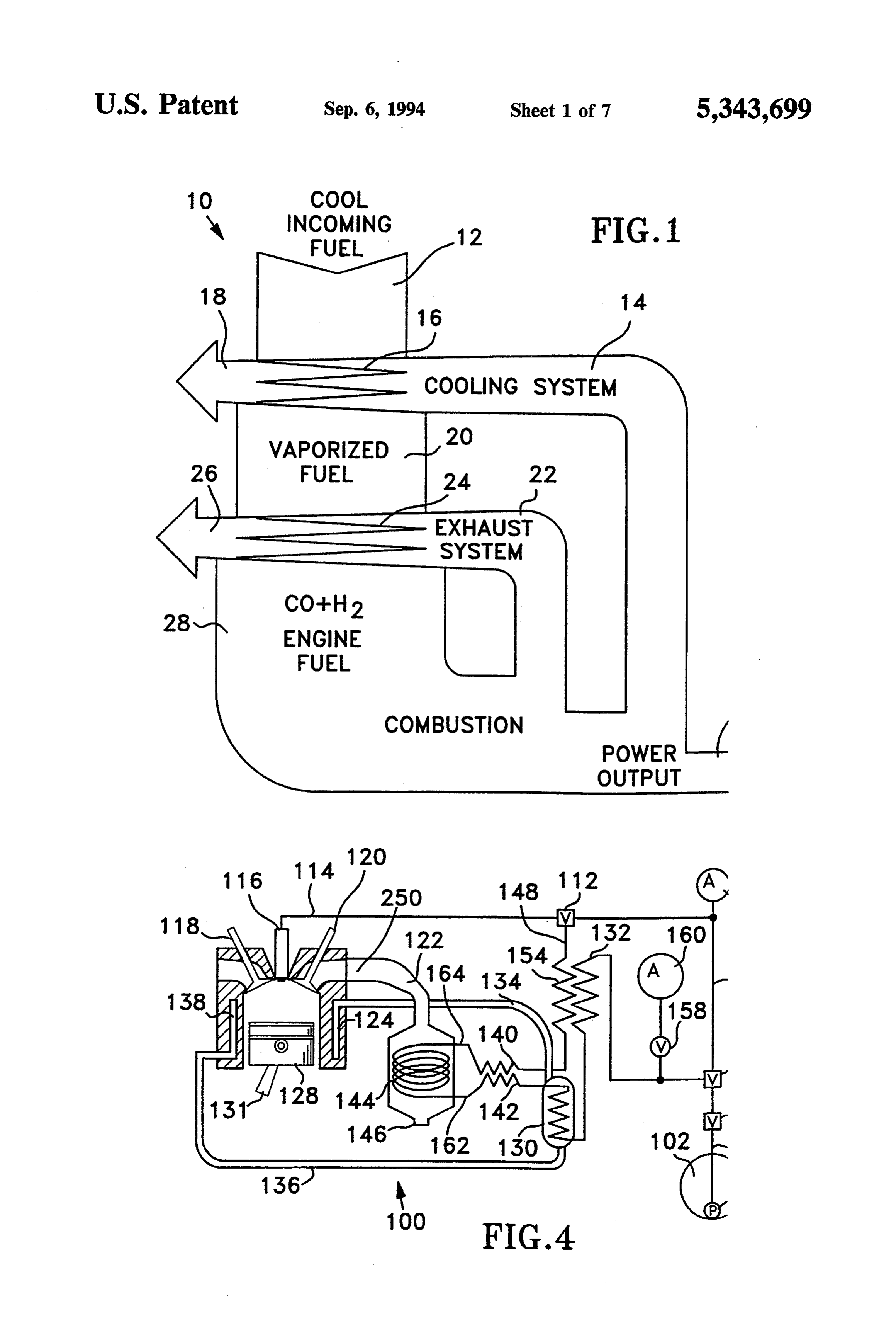
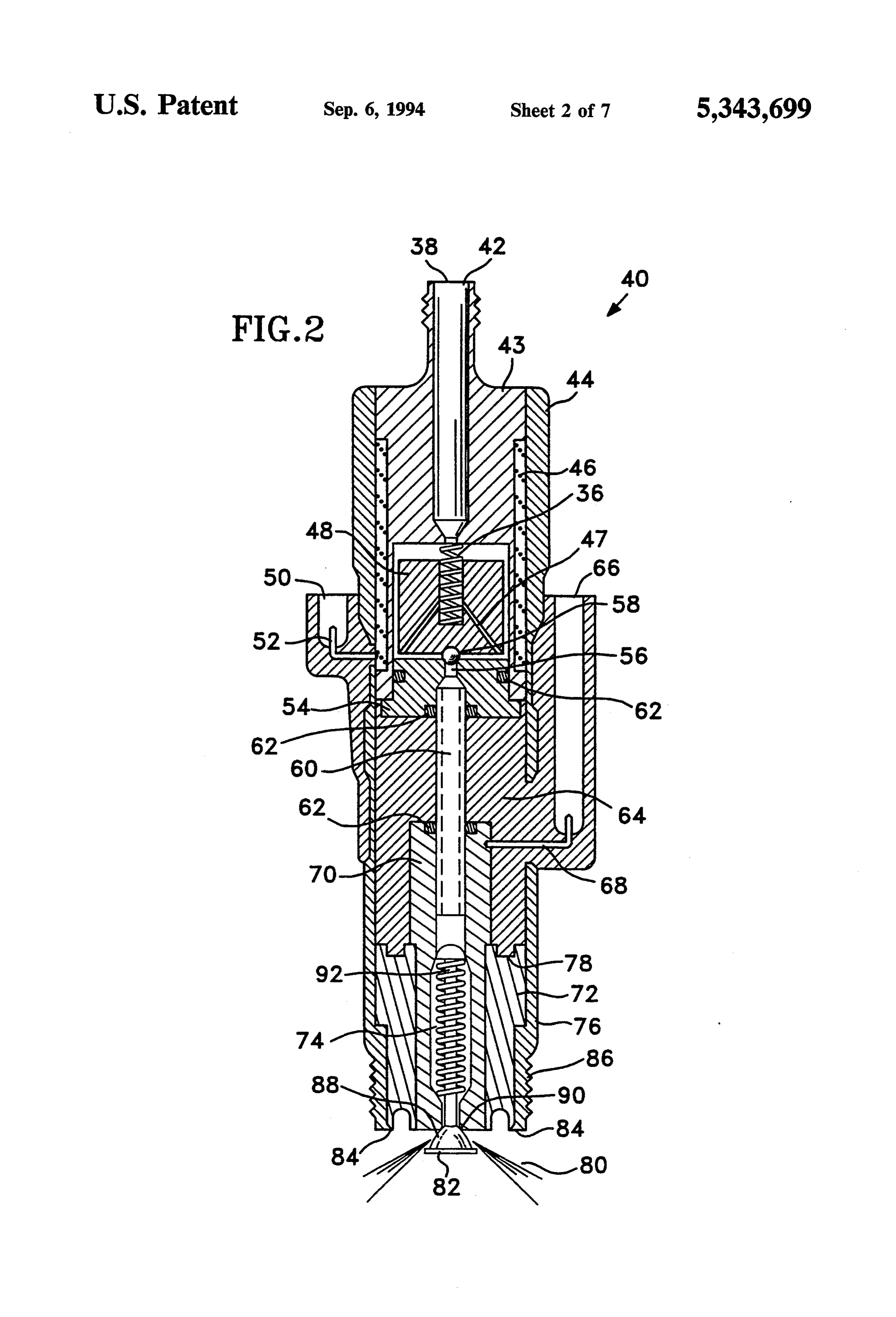
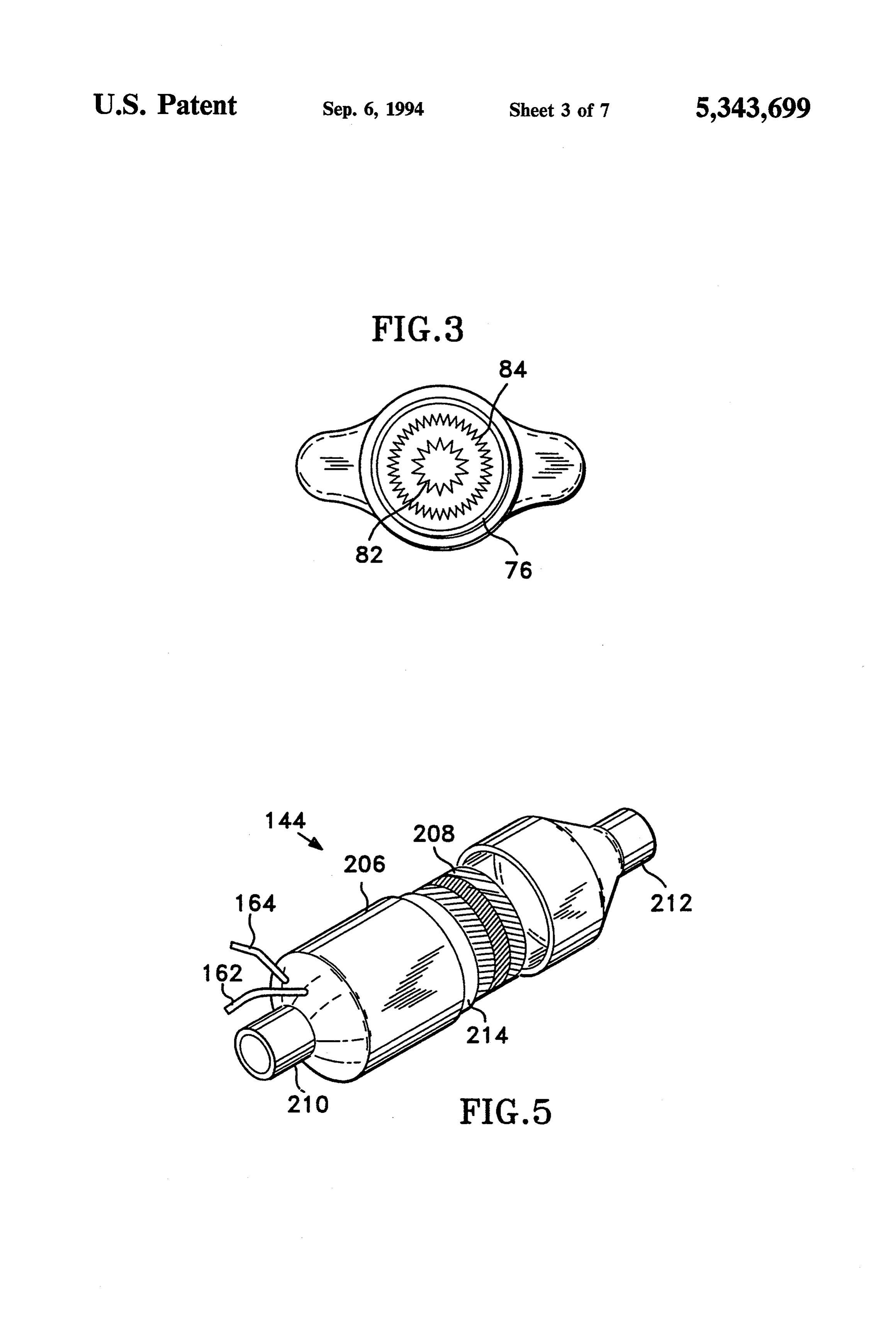
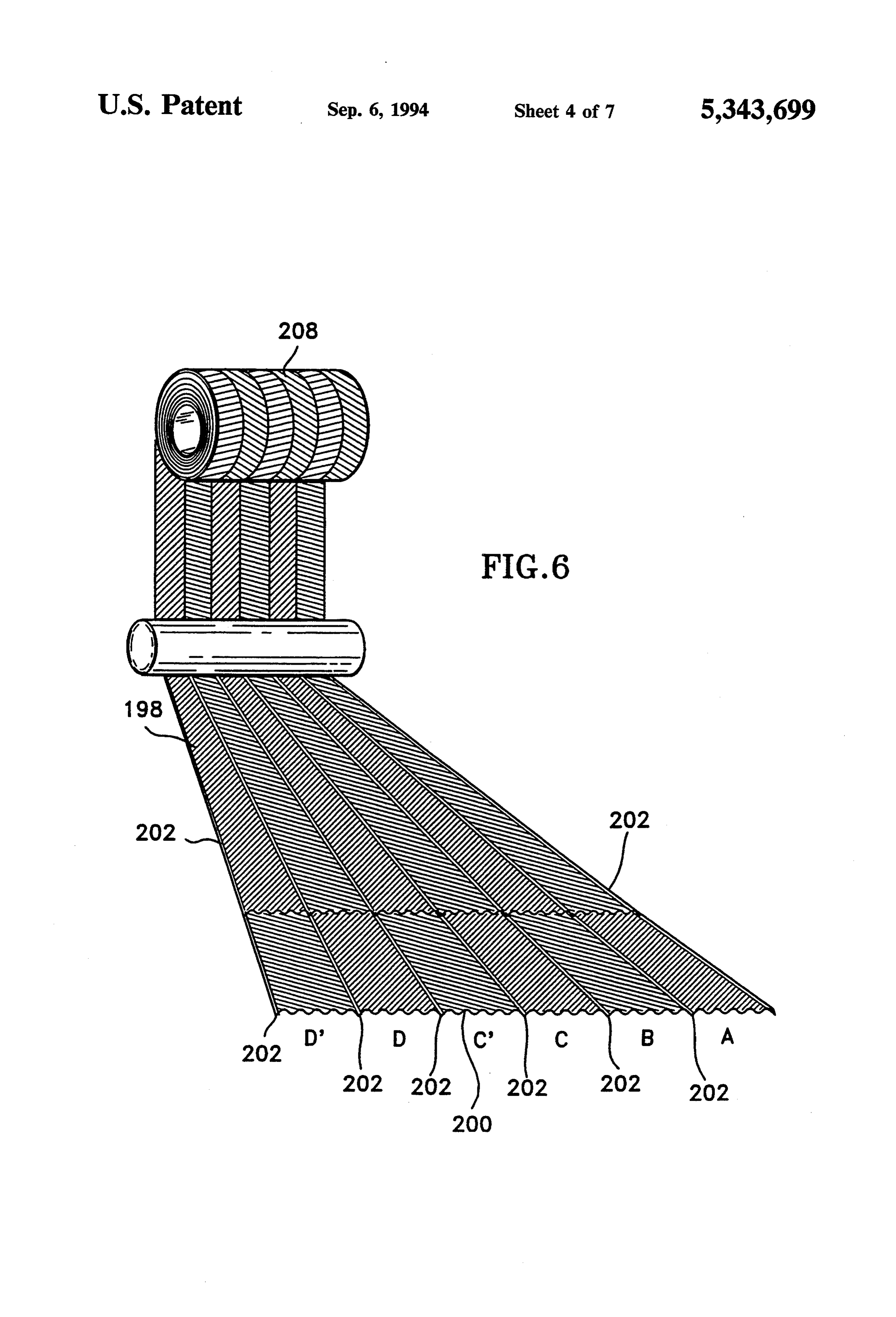
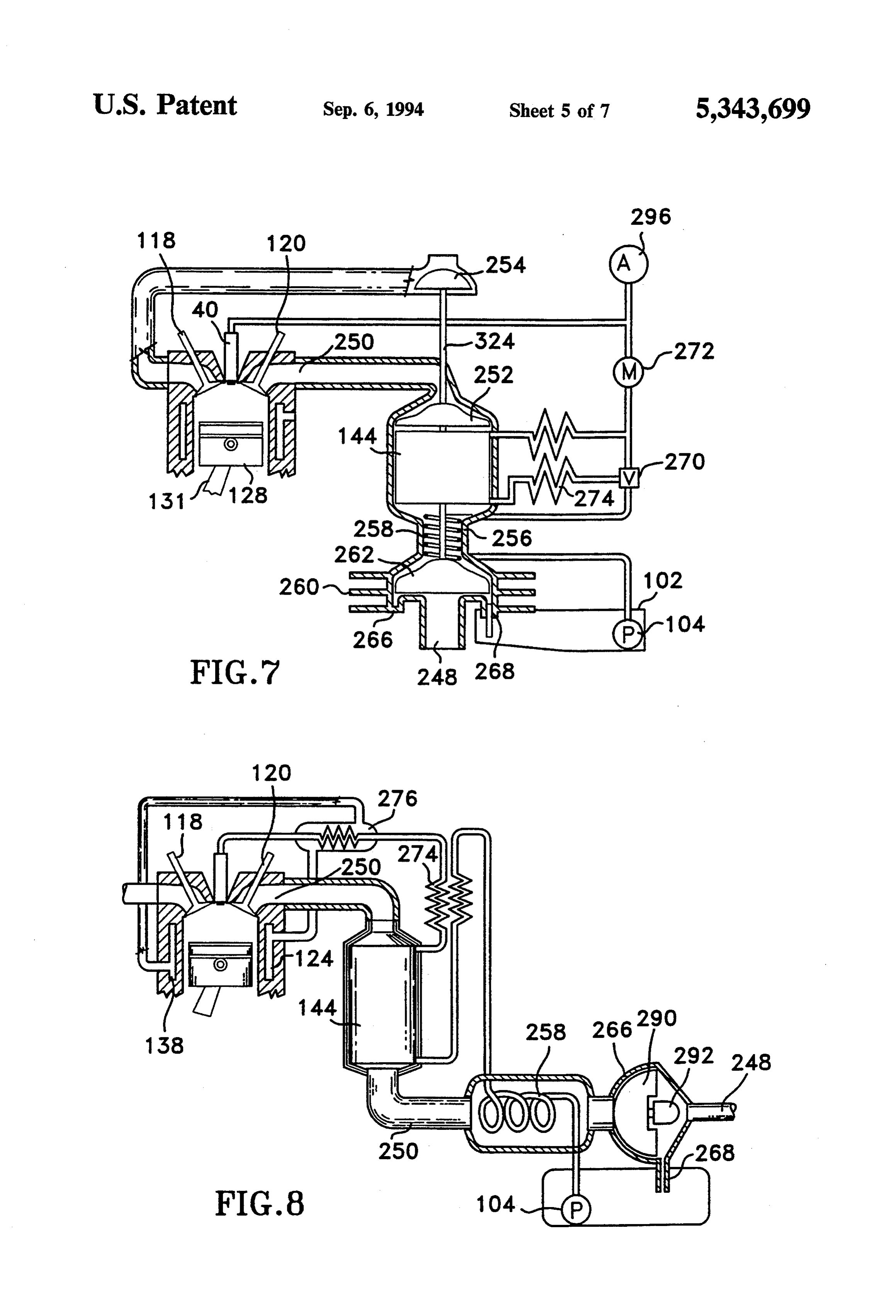
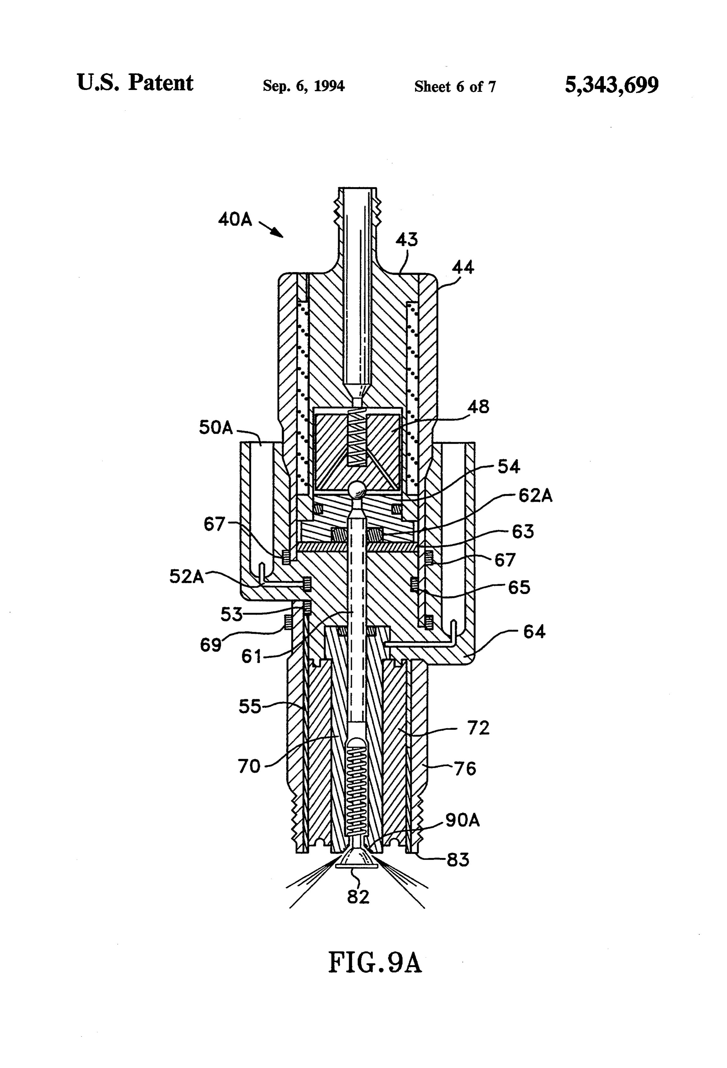
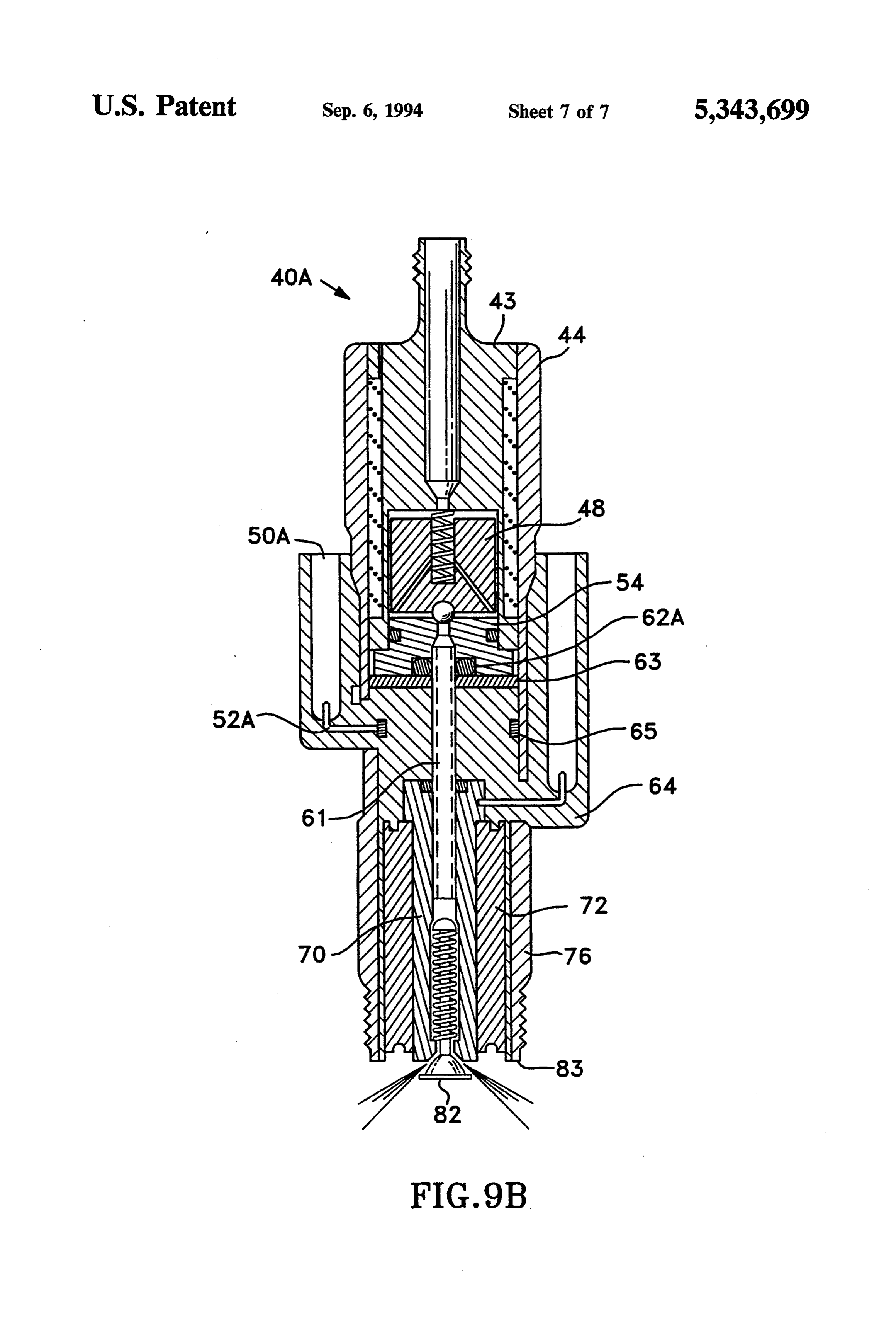
as hydrogen contains much less energy per volume 20 measure than gasoline and other hydrocarbon vapors, BRIEF DESCRIPTION OF THE DRAWINGS reduced engine-power ratings, and an increased danger FIG. 1 is a schematic illustration showing thermody of fire in underhood and hydrogen storage areas. namic processes of the invention. In addition to powering transportation vehicles, in FIG. 2 is a longitudinal sectional view of a device ternal combustion engines power many stationery de 25 constructed in accordance with the principles of the vices. Rising electric rates and urgent needs to improve present invention for directly injecting and igniting fuel the air quality in heavily populated areas provide an in the combustion chamber of an engine. important opportunity for internal combustion engine FIG. 3 is an end view of the device of FIG. 2 show powered electric generators and air conditioning sys ing the location of ignition electrodes. tems. Total energy, cogeneration, and hot-tap engine 30 FIG. 4 is a schematic circuit diagram of the invention drive systems generally connotate on-site use of the heat showing a sectional view of a representative combus rejected by an engine along with the shaft energy to tion chamber, a cooling system, an exhaust system, fuel reduce the overall energy consumption and pollutive storage, fuel pressurization, a cooling system, waste load on the environment by 40 to 75%. Such systems heat recovery exchanger, an exhaust heat recovery usually consist of an internal combustion engine, waste 35 exchanger, and delivery of engine-fuel to the combus heat recovery exchangers to safely interface potable tion chamber.
water with cooling jacket water and exhaust gases, and FIG. 5 is a perspective view of apparatus for recover a driven load such as an electric generator or a heat ing exhaust heat to be used to drive endothermic reac pump compressor. Problems with such systems include tions between fuel and an oxygen donor. low thermal efficiency of the internal combustion en FIG. 6 is a schematic view of details of a preferred gine, inadequate heat recovery from the heat exchang heat exchanger tube-fin fabrication technique utilized in ers and inadequate life of engines. Corollaries of the last accordance with the principles of the present invention. mentioned problem are unacceptable maintenance re FIG. 7 is a schematic view of details of a preferred quirements and high repair expenses. heat exchanger fin stock used to fabricate the heat ex 45 changer shown in FIG. 6.
SUMMARY OF THE INVENTION
FIG. 8 is a schematic view of one embodiment of an
An object of the present invention is to overcome the apparatus utilized in accordance with the principles of problems noted above. In accordance with the princi the present invention for recovering energy and waste ples of the present invention, this objective is accom water from the exhaust stream of an internal combus plished by providing a process for operating an internal 50 tion engine constructed in accordance with the princi combustion heat engine which comprises the steps of ples of the present invention.
thermochemically regenerating waste heat rejected by FIG. 9 shows a schematic view of another embodi the heat engine by reacting at least one conventional ment of an apparatus for recovering energy and waste fuel compound containing hydrogen and carbon with water from the exhaust stream of an internal combus an oxygen donor using substantial quantities of the 55 tion engine.
waste heat to produce a mixture of engine-fuel contain DESCRIPTION OF THE PREFERRED ing substantial quantities of hydrogen and carbon mon EMBODIMENTS: oxide and utilizing the mixture of engine-fuel to operate an internal combustion engine. Waste heat (normally rejected through the cooling Another object of the present invention is the provi and exhaust systems) is used to supply endothermic heat sion of a process for operating an internal combustion energy required to drive reactions between a primary engine comprising the steps of reacting endothermically fuel and oxygen-donor feed stocks such as air, water or a carbon containing fuel with a reagent containing hy alcohols to produce a preferred fuel called "engine drogen and oxygen to produce substantial quantities of fuel'. This enables 20% to 40% greater heatinput to the a mixture of carbon monoxide and hydrogen, injecting 65 engine upon combustion of the engine-fuel (and, there the mixture directly into the combustion chamber of an fore, 20% to 40% greater vehicle range) than could be internal combustion engine at a time that is substantially delivered by conventional engines directly burning the at top dead center and combusting the same to produce same amounts of natural gas, gasoline, or fuel alcohol
Page 12
7 r 8 feedstocks. This process is illustrated in FIG. 1. In FIG. developed across the gap between 82 and 84 as fuel is 1, heat transfer 10 is schematically depicted as energy sprayed into air in the gap to produce fuel ignition. vectors crossing each other. The width of each energy Fuel flows past metering body 56 to dielectric tube 60 vector (arrow) depicts the magnitude of energy that is when poppet 48 is lifted from seat 54. Tube 60 may be represented as heat, mechanical or chemical potential 5 sealed by any suitable means including 0-rings 62 to energy. The chemical potential energy of incoming fuel prevent leakage of the engine-fuel. Fuel is delivered and any other chemical feed stock to be used in the from tube 60 to electrically conductive nozzle 70. Com engine is shown as arrow 12. Cooling system heat is pression spring 74 acts against a wire bar 92 that is shown as arrow 14 which is reduced in magnitude as attached to check valve poppet assembly 82. shown by arrow 18 as a result of heat transfer to incom 10 Check valve poppet assembly 82 includes component ing fuel at 16. Heated incoming fuel is increased in en 88 that is normally at rest against seat 90 of nozzle 70. ergy by the heat transfer as shown by arrow 20. Heat Moveable element 88 may be formed in any suitable from exhaust gases is transferred to fuel 20 at 24 as shape as may seat 90 to produce the desired spray pat shown to reduce the energy of the exhaust gases from tern 80 for the particular combustion chamber that the 22 to 26 and increase the energy of the fuel to 28 by 15 invention serves. It is the object of spray pattern 80 to temperature increases and creation of hydrogen and produce a great degree of air utilization in combustion carbon monoxide. The engine-fuel 28 is burned in the reactions while minimizing heat losses from combustion engine to produce motive power 30 and supplies of products after ignition.
waste heat 14 and 22.
Representative temperatures of the processes shown 20 suitable to provideona large
In application smaller engines, it is often most in FIG. 1 are 70 F. at 12; 200 F. at 20, 500 F at 28; conical seat 90 for use withincluded a convex angle for a concave conical poppet 88 800 F. at 22: 225 F. at 26; 240° F. at 14; 100 F. at 18. of slightly smaller included angle. This These temperatures vary depending upon the compres cone or "cone-cone' check poppet and cone within a seat arrange sion ratio of and mode of operation of the engine in ment results in considerably larger surface to volume
ratios for fuel entering the combustion chamber than
It is preferred to provide heat exchange between hot from any number of orifices which are typical to prior engine-fuel at 28 and preheated fuel 20 in instances that art injectors.
large engines using appreciable amounts of fuel are squeezed intoFuel entering the combustion chamber is involved. Depending upon the degree of heat transfer spring 74 and dynamicconiform a thin layer by the action of forces of air compression against desired, this reduces the temperature of engine-fuel to 30 something approaching the temperature of the engine the air-side of poppet 88. Fuel combustion is extremely cooling system and enables a much lower cost construc fast because of the large surface to volume spray that is tion for the fuel delivery components because thermal presented.
degradation factors are reduced. The angle chosen for concave conical seat 90 is usu High flame speeds, wide combustible limits, high 35 ally fuel optimized for the purpose of directing the conical spray elements along the longest possible path be thermal efficiencies, elimination of particulates, ex tremely low carbon monoxide and no unburned hydro fore intersecting a surface of the combustion chamber. carbons characterize engine-fuel combustion results Ignition occurs at the beginning of fuel entry into the with the invention. combustion chamber and continues throughout the time These basic advantages are preferably facilitated by of fuel flow into the combustion chamber. This pro the use of a combination fuel-injection and spark-igni vides the greatest air utilization and the longest burning tion device 40 as shown in FIG. 2 to introduce the time for fuel before approaching a quench zone of the engine-fuel directly into the combustion chambers of combustion chamber. The present invention provides internal combustion engines after substantial compres an included angle of entry that considers the amount of sion of the air supply. Embodiment 40 is provided with 45 fuel delivery as a function of piston speed. At idle con the same thread and reach 86 as spark plugs for the ditions and low piston speeds the amount of fuel deliv engine served by the invention. In instances that the ery is small. At maximum torque production, high invention is applied to Diesel engines, the design at 86 speed conditions the amount of fuel delivery is much duplicates the configuration of the conventional fuel larger and occurs during a greater number of degrees of injector in the area that provides a seal to the combus 50 crank-shaft rotation. The present invention provides tion chamber. optimized air utilization for different flame speeds by As shown in FIG. 2, pressurized engine-fuel enters providing an included angle for the fuel cone that aims embodiment 40 at 42 and is prevented from entering the the entering rays of injected fuel at the outer rim of the combustion chamber as fuel spray 80 until just before piston during the highest fuel flow rate of the intended pressure increases are needed for the power cycle in the 55 duty cycle.
combustion chamber. At the proper time, fuel is al For optimizing the fuel pattern for hydrogen or en lowed to pass solenoid poppet 48 which is actuated by gine-fuel, the included angle is large and the fuel is an electromagnetic force resulting from the flow of aimed at the piston rim at near top dead center. For current in winding 46. Poppet 48 is preferably moved slower burning natural gas or petrol fuels the included against the direction of incoming fuel flow. Voltage to 60 angle is smaller and the fuel is aimed at a piston-rim drive current through coil 46 is supplied by connection location somewhat after top dead center. The opportu 52. Coil 46 may be grounded to conductive body 48 or nity is provided to optimize power production for start returned by suitable connection (not shown) such as 52. up conditions in which a conventional fuel such as natu High voltage for ignition is delivered by a suitable spark ral gas, gasoline or Diesel fuel is burned and then after wire and terminal in high voltage well 66. Connection 65 production of engine-fuel to have extremely advanta 68 delivers the high voltage to conductive nozzle as geous operation including production of more power sembly 70. High voltage is carried by compression and better economy than with conventional fuel injec spring 74 to wire bar 92 to poppet 82. Spark plasma is tors. Important applications include. military vehicles,
Page 13
emergency electric generator drives, police cars, ambu pressure over the piston compared to the pressure under lances, and fire trucks. the piston. More mechanical work must be done to It is preferred to form poppet 88 from sheet material overcome the manifold-vacuum condition than if there and to provide highly angular points on the lower skirt was no impedance to air entry.
as shown for the purpose of reducing the discharge Prior-art approaches depend upon variable air throt voltage for plasma generation. It is preferred to form tling in all practical modes of operation to produce electrode skirt 84 with highly angular points, as shown, homogeneous, substantially constant-ratio mixtures of for the same purpose. Alternate geometries of poppet 88 fuel and air at all levels of power production. In order to and form for seat 90 that are particularly suitable to be spark ignitable the air had to be throttled so the fuel combustion chambers of larger displacement engines is O could be reduced from highest power ratings to lowest a spherical form in which the spherical surface of 82 power ratings. This type of operation greatly reduces contacts a concavo-spherical seat 90 of somewhat part-load efficiency by increasing the pressure differ larger radius. This sphere within a sphere or "sphere ence through which the piston must operate during sphere' check poppet and seat arrangement results in a intake conditions.
fuel spray cone 90 that tends to provide increased sur 15 The present invention facilitates use of multiple in face to volume and greater air utilization than the cone take valves, sleeve valves, combined intake and exhaust cone arrangement described previously. In light valves, and other arrangements that impede the air less weight engines with high piston speeds, such as racing than conventional arrangements that produce air swirl engines, it is preferred to maximize the flame speed by in the combustion chamber. The present invention con forcing production of an even greater degree of fuel 20 templates unimpeded air entry into the combustion surface to volume ratio by providing a convex-spherical chambers at all power levels for maximum mechanical seat 90 on which a convex-spherical surface of 82. efficiency regardless of the power level. This provides In order to achieve satisfactory fuel penetration into more power, smoother operation without "dead spots', the compressed air mass of larger combustion chambers and a greater range of acceptable speed-torque condi it is advantageous to provide channels such as 88A or 25 tions.
90A in the surface of 88 or 90. These channels 88A or It is preferred to operate the present invention at 90A carry greater fuel flow than the areas between the overall fuel-air ratios ranging from far excess air at low channels and provide greater fuel penetration than from power settings to excess air at highest power settings. areas between the channels. Helical and other patterns Completion of combustion processes and excess-air of channels in 88 that provide acceleration of the fuel at 30 insulation of heat released by combustion characterize angles with the shortest distance of travel from the the operation at all power levels.
orifice in nozzle 70 to the combustion chamber, cause The known limits of flammability, flame speed, and rotation of component assembly 82 and 88 which is heat of combustion of various fuels including the main advantageous in polishing seat 90 to keep it clean and constituents of engine-fuel shown that hydrogen, which uniform. 35 characterizes engine-fuel combustion processes herein These various cone-cone, sphere-sphere, sphere-cone provides a flame speed that is more than 7.5 times that and cone-sphere channel geometries provide important of common fuel selections such as methane. This ena improvements over the prior art. Prior-art Diesel fuel bles much later injection and ignition of engine-fuel injectors and the injectors anticipated by U.S. Pat. Nos. than conventional fuels such as methane or gasoline and 3,830,204; 3,094,974 and 3,316,650 utilize sprays of fuel 40 results in greatly improved brake mean effective pres from one or more individual holes to spray fuel into air sure per BTU of fuel value by not incurring back work masses within the combustion chamber. Embodiments during slow-burning pressure rise in the compression of the present invention deliver fuel in a conical form cycle of the operation.
having much higher surface to volume ratio and does so Engine-fuel combustion is characterized as an ex in a pattern that assures completion of combustion 45 tremely-fast colorless combustion process and the de events before the fuel reaches quench zones within the gree of heat loss by radiation to combustion chamber combustion chamber. These various embodiments an surfaces is negligible compared to conventional engines. swer the need to optimize air utilization requirements in The present invention facilitates injecting and igniting virtually any combustion chamber design without re engine-fuel just after top dead center (TDC) to provide sorting to efficiency-sacrificing air swirl and intake-air 50 much quieter operation because piston knock and vibra throttling techniques. tion due to untimely ignition during the compression Injection of the fuel into air produces a local zone of cycle are eliminated by the invention. Converted en fuel-rich conditions within an envelope that provides gines runs cooler, smoother, and quieter than with con excess air to fuel conditions which is surrounded by ventional fuel conditioning and delivery systems. insulative air. Ignition occurs by passage of ignition 55 FIG. 4 shows the method of the invention in a sche spark-plasma energy through the alternate layers of air, matic circuit of thermal, mechanical, and thermochemi excess-air-fuel zones, fuel-rich zones, excess-air-fuel cal operations. An improved heat engine 100 is shown. zones, and air. The greatest flame speed occurs in the Fuel is stored at 102. The fuel may be any suitable selec fuel-rich zones. Even at the highest piston speeds this tion such as compressed natural gas, fuel alcohol, liquid creates a fuel-rich, higher-speed combustion-process 60 natural gas, gasoline, or Diesel fuel. Liquid fuels stored driver within excess air zones that assures completion of at ambient pressure are preferably pressurized by pump combustion events in slower combustion rate areas. 104 to required fuel injection pressure which ranges Prior art devices depend upon swirl of the air in the depending upon fuel viscosity, surface tension, molecu combustion chamber to deflect fuel sprays into helical lar weight, and carbon to hydrogen mass ratio, from paths in order to prevent penetration to quench zones. 65 about 100 to 1,500 psi above the compression pressure Creating swirl of air in the combustion chamber is pro of the engine. At start-up conditions the cold fuel is duced by impedance to air entry. This reduces the me delivered to three-way valve 108 and directed to the chanical efficiency of the engine by incurring reduced engine through line 110, three-way valve 112, and fuel
Page 14
injector 116. Fuel is sprayed into and ignited within all change to feed stock fluids in heat exchangers 140/142 combustion chambers that are about 5 to 70% into and 132/154 as shown in FIG. 4. power (expansion) cycles. Rapid heating of the air and Heat exchange and catalytic conversion of feed stock power delivery results. The engine is started without a fluids within 206 are provided by flat tube coil 208. starter motor. After the engine is started, injection and Tube coil 208 is preferably made from two strips of ignition timing are advanced to provide optimum oper metal that are formed to provide extremely high surface ating conditions. areas for heat transfer and catalytic actions upon mix This is an important improvement over prior art tures or solutions offeed stock fluids. One such embodi methods of starting an engine. It results in much re ment 200 for the strip stock is shown in FIG. 7. Strip duced package weight, initial cost savings, and elimina O 200 is formed to have corrugated, knurled, herringbone, tion of starter-system maintenance expense. It is pre or otherwise circuitous surfaces as shown. It is bonded ferred to use a conventional electronic microprocessor to sheet 198 along seam 202 as shown. Sheet 198 may be with memory for monitoring, starting, and optimizing formed like 200 or provided as an essentially smooth the engine. Piston locations within combustion cham sheet as shown in FIG. 7. A particularly high surface to bers are stored at shut down and recalled for the start 15 volume catalytic heat exchanger is formed from sheets up routine. The microprocessor facilitates safe opera 198 and 200 in which each sheet is corrugated to from tion by instantaneous monitoring of oil pressure, tem herringbone designs in the areas between seams 202. The herringbone corrugations of each sheet are oppo perature, vibration, and other vital instrumentation to site provide emergency shut-down if the engine has no oil 20 the other sheet. This provides parallel internal tube or if other malfunctions occur. ways between seams 202 that have circuitous internal Compressed gas fuels stored in 102 are pressure re channels to cause turbulent flow of reactants at all duced from the storage pressure and regulated at the points of fluid progress through the reactor and turbu lent flow of exhaust gases through the corrugated desired pressure of delivery. It is preferred to use an spaces electric pump for pressurization of liquid fuels. In in 25 bly. that are provided between layers of the assem stances that the bearing designs require pressurization Tube ways are manifolded to provide the desired of oil to the crank and camshaft bearings before startup, circuit through the reactor. It is preferred to have coun it is preferred to provide a safety interlock to prevent ter-current fuel injection until oil pressurization by a suitable hand entering theheat exchange in which the coolest fluid reactor receives heat from the coolest ex or electric pump has been accomplished. haust gases. After manifolding the tube-ways, the as After the engine has warmed up and the temperature sembly is spiral wound on a tube and the assembly is at thermochemical converter 144 has reached about 500 F., valve 108 shuttles to direct fuel to line 152 and encased in insulated canister 206. The spiral-wound to heat exchanger 154. The engine continues to operate assembly is shown in FIG. 5. Heat additions through catalytic surfaces are pre on fuel supplied by accumulator 152. Fuel and any other 35 ferred to perform the desired reactions of Equations desired oxygen donor (such as air) from tank 160 is 1-11. The pressurized by suitable pump 158 and heated in heat vides highembodiment shown in FIGS. 5, 6, and 7 pro exchanger 130 by cooling fluid delivered from the en tions. Sheet materials for reactor with thermal conductivity
catalytic func may be a wide gine by conduit 134. Combinations of fuel from tank 102 variety of alloys and surface coatings for iron, alumi and water or another oxygen donor from tank 160 are num and copper based sheet structures. The catalyst called "reactants'. Further heating of the reactants is selections have further roles of serving as bonding or accomplished by countercurrent exchange between 140 sealing agents in the catalytic heat exchangers. After and 142 with engine gas produced in thermochemical forming, seam welding, manifolding, and coiling, the converter 44. assembly may be furnace or induction brazed to bond Final heating of the reactants and production of en 45 contact areas inside the flat tubes and between layers of gine gas results from catalytic processes in converter flat tubes. This greatly strengthens the assembly. 144. Hot exhaust gases ranging in temperature from Sheet strip selections are first plated or hot-dip coated over 1100 F. to 600 F. depending upon the duty cycle to uniform coating thicknesses by any suitable produc are delivered by exhaust conduit 122 to thermochemical tion line technique and then roll-bonded or seam converter 144. Cooled exhaust gases pass through ex 50 welded along the seam zones 202. It is preferred to bond haust conduit 146. Cooling jacket fluid is returned to the all areas of contact between sheet 198 and 200 to arrest engine through conduit 136 for circulation through pressure stresses from the fluids within the flat tubes. It suitable cooling passages 138 and 124. Another heat is also anticipated that diffusion gradients of desired rejecting circuit comprising an ordinary radiator and catalytic agents would be produced by multiple platings thermostatic valve may be used in series or in parallel 55 or coatings followed by heat treatment. with the circuit of 134,130, and 136. Although zinc and copper have been recorded in Engine-gas is delivered to three-way valve 112 and prior art efforts to dehydrogenate alcohols, it is impor directed to the engine through line 114 and fuel injector tant to note that the present invention uses catalytic 116. It is preferred to use the combination fuel-injector alloys of zinc and copper or coatings containing zinc and spark-ignitor shown in FIGS. 2 and 3. and copper in solid solution to provide heterogeneous Details of the preferred embodiment for thermo dehydrogenation of alcohols, organic solutes, and water chemical converter 144 are shown in FIGS. 5, 6 and 7. more or less simultaneously. A series of intermediate Recovery of waste heat from the engine is provided by reactions are believed to be responsible for the overall passing hot exhaust gases into inlet 210 of canister 206. reactions as shown in Equations 1-11. A particularly Heat exchange from hot exhaust gases heats the feed 65 useful aid to the understanding of intermediate reactions stocks delivered through tube 162. Thermochemically is found on pages 535 through 586 of the Second Edi converted engine-fuel leaves reactor 144 through tube tion of the Kirk-Othmer “Encyclopedia of Chemical 164 and is preferably cooled by regenerative heat ex Technology' and this reference is incorporated herein.
Page 15
Alloy sheet catalysts have considerable ductilities frame, cogeneration heat requirements for air condi and allow cold working to form turbulence-inducing tioning, and further preheating of feedstock supplies of patterns, such as corrugations or crossed rows of em wet-fuel alcohols are contemplated.
bossments depending upon the hot endurance strength Pressurized engine-fuel is controlled by solenoid of the selected sheet system at the operating tempera operated, three-way valves 108 and 112. Engine-fuel in ture chosen for the application. Sealing the lower sheet heat exchanger section 154 is monitored for tempera to the upper sheet is accomplished by metallurgical ture and pressure. Valve 112 is operated "OPEN” to joining along 0.090" wide seams 202 between 1' wide allow flow from heat exchanger section 154 to the fuel channels 204. A suitable sheet-stock thickness for strips injectors if the temperature and pressure are within 198 and 200 of the embodiment of FIG. 6 is 0,010' with 10 preset limits. Valve 112 is "CLOSED' to flow from 154 a corrugated channel depth of 0.015' to 0.060". This but "OPEN” to flow from pump 104 and provides as gives a very low clearance volume within the assembled sured engine start-up and operation with injection of reactor coil. liquid fuel until desired temperatures and pressures are The inventory of engine-fuel is minimized by the low developed in section 154. During operation with liquid clearance volume in all parts of the fuel conditioning 15 fuel, map "A' of the fuel management system is used. system. To further assure safety, pressure is monitored During operation with gaseous engine fuel map "B" is in lines 106, 152, and 114. If the rate of pressure change used. Operation between maps A and B is electronically exceeds a narrow preset value, pump 104 is stopped and switched in correspondence to the operation of solenoid valve 170 is closed to prevent entry of additional fuel to valve 112.
the fuel-conditioning system. Because heat exchangers 20 Fuel entering the combustion chamber is ignited by 130 and 144 are housed in water cooling or exhaust sparks that pass through alternate layers of air-fuel-air systems, additional fail-safe virtues are inherent. If a and ignition is assured regardless of the overall combus leak in heat exchanger 130 or 144 would occur pump tion chamber inventory of air and fuel. Overall air to 104 would shut down, normally-closed solenoid valve fuel ratios of 1,000 to 1 are as assuredly ignited by the 170 would close, and the small inventory of escaping 25 invention as are air to fuel ratios of 15 to 1. The inven fuel would be contained in water or in the exhaust pipe tion provides best fuel economy and minimum emis where it could do no harm. sions during cold-engine conditions with direct-injec Fuel pressures of 10,000 psi at 1,000 F. are practical tion and spark-ignition of liquid fuels. Later, after reach with catalyst sheets having yield strengths of 20,000 psi ing the engine's designated operating temperature, the or more because of the tightly coiled and bonded spiral 30 invention provides useful recovery of engine waste heat assembly. Additional aid in arrestment of stress is by by operating on gaseous fuels that produce considerably transfer of compressive preload from the outer contain more energy upon combustion than the feedstock liquid ment cylinder 206. fuels. The invention facilitates these fuel efficiency ad It is preferred to thermally isolate coil 208 from canis vantages without sacrificing specific power ratings of ter 206 by refractory fiber sleeve 214. This provides an 35 the engine in power-per-thermal-unit comparisons. This air cooled containment cylinder 206 in which tensile is an extremely important aspect of the invention be loading occurs to produce compressive loading of coil cause it is generally necessary to specify 30% to 150% 208. Use of the insulator sleeve provides a space for " larger displacements and increased compression ratios OD, 0.095' wall manifold tubing of a 60%-Cu/38%- (than for carbureted gasoline fuels) when use of gaseous Zn/1%-Sn alloy, which is also used to convey engine fuel is contemplated. The larger engine requirement gas to heat exchanger section 130 and to fuel injectors cascades into a number of application penalties includ 116. In applications where additional safety consider 1ng:
ations are warranted it is preferred to clad tubing 106, 1. Larger tires, shock absorbers, springs, starter mo 152, 148, and 114 with a sheath of high-strength stainless tors, batteries, alternators, power assist units, transmis steel such as 177 PH. Inlet manifolding and a core for 45 sions, and brakes for a greater curb weight in transpor the spiral assembly is provided by joining the coil to a tation applications.
3" diameter, 0.187' wall tube that is internally parti 2. Greater requirements for iron, chromium, molyb tioned to provide desired series-parallel flow of vapors denum, vanadium, manganese, nickel, and petroleum through C and C and then in parallel through D and reserves. More energy is required to mine, mill, refine, D'. Exhaust gases pass into the reactor from connec SO alloy, cast, forge, machine, and build the larger engines. tions 210 to 212 to provide a modified counter current The greater demands upon finite reserves of critical heat-exchanger, endothermic-reactor combination. materials produce higher prices per pound and force Engine-cooling-jacket water at 180 to 250 F. (if it inflation in the world's economy.
exists) may be circulated in an additional section of heat In addition, the invention overcomes the difficult exchanger 130 to provide standardization of the engine 55 problem of back-firing, wherein hydrogen is inoppor gas temperature. In this instance, the cooling jacket tunely burned within the intake manifold of carbureted water would be circulated from 124 to 138 through heat or manifold injected engines. This problem stems from exchanger 130 as shown in counter-current arrange the fact that hydrogen will support combustion in re ment to flow of engine gas. markably wide fuel-to-air ratios and because flame An alternate arrangement for providing desired heat speeds in hydrogen combustion are extremely high. The exchanges is to build heat exchangers 130 and 132/154 invention prevents back-firing by eliminating any mix in one assembly with thermostatically-controlled en ing of hydrogen and air until the fuel-injection event gine-jacket water circulation from inlet 124 to 138. In within the combustion chamber.
emerging engines with material selections that allow Production of engine-fuel from inexpensive fuel alco combustion-chamber wall temperatures of 500 degrees 65 hols and compressed or liquid natural gas is facilitated. F. and higher, it is preferred to provide standardization A longer-range regime would use coal-sourced meth of the engine-fuel temperature with split-phase heat ane and wet methanol. The present invention thermo pipe heat exchangers. Final heat sinking to the vehicle chemically processes and utilizes feedstocks that are less
Page 16
refined and less expensive than gasoline or Diesel fuels. Another problem that the present invention over In use with conventional gasoline or diesel fuels, consid comes concerns the ability to gain as much power per erable range and thermal efficiency improvements are BTU or calorie of heat release from engine-fuel as gaso offered. line produces in spark-ignited engines. It is generally Fuels such as natural gas, coal gas, acetone, methanol, conceded that gaseous-fueled engines require consider ethanol, propanol, propane, butane, and butanol are ably larger engine displacements than gasoline-fueled attractive replacements for petroleum fuels. The fuel engine per unit of power development. This is because alcohols and light paraffins are readily produced from previous attempts to use gaseous fuels have mixed the coal, peat, oil shale, tar sands, natural gas, solid wastes, fuel with air during intake processes. Considerable or freshly-grown biomass. The United States has about 10 breathing capacity and cycle energy have been diverted 20 times as much energy reserve in coal as the Middle to introducing the gaseous fuels into the engine. In the East has in oil reserves. Using coal-sourced fuel alco present invention, the full breathing capacity of the hols is facilitated and the invention allows increased engine is reserved for intake of excess volumes of com volumes of petroleum to be used for making polymers bustion air. Brake mean effective pressures (BMEPs) and petrochemicals. 15 are higher because the pistons are not required to do A well-recognized and long-standing problem con work (against crankcase atmospheres) as a function of cerning fuel alcohols is the energy-intensive nature of manifold vacuum.
producing fuel alcohols from coal or biomass. Water Water requirements not met by using wet alcohols present in the coal or biomass feedstocks, along with 20 may be supplied by condensation of water vapor from steam used in reactions with carbonaceous feedstocks to the exhaust gases of the heat engine employing the gasify the feedstocks requires considerable energy to invention. Approximately one gallon of water is pro reach process reaction temperatures. After generation duced from each gallon of hydrogenous fuel burned by of mixtures of hydrogen and carbon monoxide (water a heat engine. Illustratively, one mole of octane (gaso gas) and catalytic synthesis of fuel alcohols, consider 25 line) thermochemically regenerated with eight moles of able additional energy often is required to remove water water burns in air to produce seventeen moles of water. condensates and produce anhydrous fuel. Only eight moles out of the seventeen needs to be col Commercial production of methanol by the Oxyl lected and recycled:
process, the action of fermentation enzymes, or destruc tive distillation of cellulose could be considerably less 30 energy-intensive if the product could be used "wet' C8H18 + 8H2O-G 8CO + 17H2 ("ENGINEFUEL) Eqn. 13 (130- to 190-proof) rather than “dry” (200-proof). This invention facilitates the advantageous usage of natural 8CO + 17H2 + 12.5O2-G-8CO2 + 17H2O Eqn. 14 gas, wet-fuel alcohols, water-soluble or alcohol-soluble organic compounds, and engine waste heat by the illus 35 trative reactions shown below. Similarly only one mole of water out of three needs to collected when methane is converted to engine-fuel.
WET NATURAL GAS plus WASTE HEAT yields
CH4+ H2O-Ge CO + 3H2 (ENGINEFUEL) Eqn. 15
HYDROGEN and CARBON MONOXDE
The reactants in Equations 1-8, consisting of one or more alcohols, one or more soluble organics, and water, Nature ultimately condenses water from heat-engine are heated by exchange with exhaust gases to tempera 45 exhaust streams. The familiar plume of condensed water tures ranging from 225 to 1,000 degrees Fahrenheit. Hot droplets that form in automobile exhaust streams during organic-compound vapors and steam mixtures are cold weather are an example of prompt condensations. passed through a catalyst to produce mixtures of carbon Rain from clouds and fog are examples of more delayed monoxide and hydrogen. In Equation 9, natural gas or condensations in which automobile exhaust contribu biomass methane is reacted with steam to produce hy 50 tions are added to water evaporated from oceans, lakes, drogen and carbon monoxide. Equations 10 and 11 and rivers and to water transpired by vegetation. typify the reaction of gasoline and diesel blends with a In order for approximately half of the water in an liquid containing oxygen to produce carbon monoxide engine's exhaust to be recaptured for thermochemical and hydrogen upon endothermic reaction. These reac regeneration, most of the exhaust stream must be cooled tant blends would also contain emulsifiers for long-term 55 to approximately 200 degrees F. Assuming daytime storage purposes. The vaporous product or engine gas high ambient temperatures of 120 degrees F. (and most is used in the combustion chamber as a stratified-charge places would have a lower daytime high temperature), fuel and is spark-ignited. there would be about an 80 degree (F) gradient for heat Heat-release potentials for complete burning of the exchange to the atmosphere. Heat exchanges shown in engine gas constituents exceed the complete burning 60 FIG. 8 provides extremely high surface area and turbu potentials of the fuel feedstocks by 20% to 40%. In lence in the heat exchange process.
creases in heat-release potentials are derived by ex Flat-tube heat exchanger components used in 144 and change from engine waste heat to the endothermic 256 are self-reinforcing and extremely conservative in reactions generally shown in Equations 1-11. Equally the use of corrosion-resistant materials. These designs important is the opportunity to use wet fuels that are 65 have been proven capable of extremely rapid fabrica 30% to 50% less energy-intensive in initial production tion rates. The regime of FIG. 8 is suitable, therefore, than are the anhydrous alcohols, phenol, or other or for the high-volume production requirements for auto ganic-compound counterparts. motive applications.
Page 17
Collection of water from the exhaust stream is prefer The present invention provides a cycle with more ably accomplished by the process illustrated in FIG. 8. molecules of expansion products than compression mol Exhaust gases 250 from combustion chambers of an ecules. This results in greater power ratings for the internal combustion engine are first used to drive a same engine and increases the thermal efficiency of the suitable air motor 252 which in turn drives a suitable process.
compressor 254 to increase the amount of air entering It is anticipated that large stationary engine applica the combustion chambers of the engine. Exhaust gases tions with more or less constant speed operation, will leaving air motor 252 enter heat exchanger 144 for the place thermochemical reactor 144 in front of power endothermic production of engine-fuel. Exhaust gases turbine 252 for the purpose of improving the overall pass from heat exchanger 144 to heat exchanger 256 for O thermal efficiency of the system. In mobil applications heat rejection to engine-fuel reactants in fin-tube 258 where it is desired to gain the highest power to weight and to the atmosphere from fins 260. A second air motor ratio, it is anticipated that power turbine 252 would be placed in front of thermochemical converter 144 as 262, which is mechanically coupled to air motor 252 shown.
and compressor 254 by shaft 264 as shown, extracts 15 In instances that it is not desired to add recov additional work from the expanding exhaust gases and ered water to stored fuel feedstocks in tank 102, con centrifugally accelerates condensed water collection densed water from 268 may be added to reservoir 160 as shroud 266 for delivery of water through tube 268 to shown in FIG. 4. When the rate of water collection tank 102. exceeds the desired rate of storage (as is the case in cool Engine-fuel reactants are stored in tank 102. Pump weather) heat rejection from fin 260 is attenuated to 104 delivers reactants to fin-tube 258 of countercurrent 20 reduce the rate of condensation to collector shroud 266. heat exchanger 256. Reactant fluid is then further In instances where it is desireable to reduce the ther heated in regenerative heat exchanger 274 as engine mal signal of heat engines, the invention provides ex fuel is cooled by exchange to incoming supplies offeed haust gas temperatures approaching ambient tempera ture. This effect may be emphasized by sizing exducer stock reactants traveling to enter the coolest region of 25 turbine thermochemical converter 144. Fuel injection and igni 262 for expansion of the exhaust gases to ambi tion of engine-fuel in the combustion chamber is prefer entCreating pressure.
carbon monoxide and hydrogen from water ably accomplished by embodiment 40 which is shown in and hydrocarbon fuels by regenerative use of engine detail by FIG. 2. waste heat provides at least 20% more range and fuel Hot exhaust 250 contains all of the water vapor pro duced by the combustion process. As heat is extracted 30 economy. This process virtually eliminates carbon mon the relative humidity reaches 100% and liquid water oxide and unburned hydrocarbon emissions because combustion of engine fuel is characterized by extremely can be extracted by exducer turbine 262. Exducer tur fast hydrogen burning characteristics to force carbon bine 262 is preferably made from materials such as car monoxide to complete bon-fiber reinforced liquid-crystal polymers that are not 35 cess air to yield carbon combustion processes with ex corroded or eroded by condensing water droplets. Tur ciencies of the converted engine include: process effi dioxide. Improved bine 252 is preferably made from conventional iron 1. Engine-fuel produces about 20% more heat than based superalloys that have traditionally been selected burning the feedstock fuel. for resistance to oxidation and creep in such applica tions. Compressor 254 is preferably made from alumi by2.converting The invention reduces combustion-radiation losses num, magnesium or polymer compounds depending radiation enginehigh-radiation fuels.
feedstock fuels to low upon the size of the engine and required life of system 3. Engine-fuel burns about 7.5 times faster than feed components.
A particularly advantageous aspect of the present stock fuels. This allows the invention to produce a pres invention is the gain in expansion gases compared to 45 or after that sure rise is much faster and to occur substantially at compression gases. For the greatest part of the com efficiencytop-dead-center and thermal conditions. Both mechanical efficiency are improved.
pression cycle only air is present. At the time near top 4. The invention burns engine-fuel in locally fuel-rich dead center when pressure increase is desired, engine conditions within excess air to enhance high-flame fuel is injected and combusted to produce far more hot speed advantages.
expansion gases than would be present if conventional 50 5. The invention burns engine-fuel in locally fuel-rich fuels were used as homogeneous charges or if conven conditions within excess air to reduce conductive losses tional fuels were injected and burned as stratified to combustion chamber surfaces.
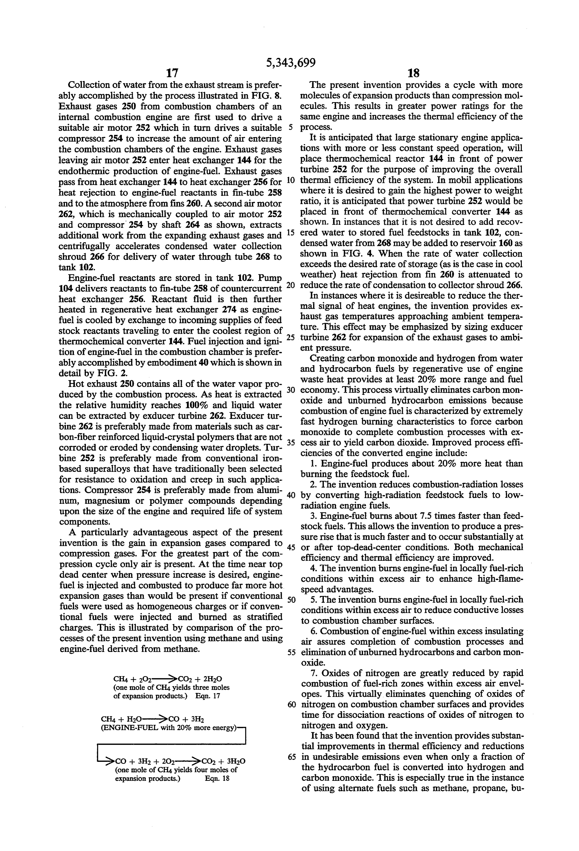
charges. This is illustrated by comparison of the pro 6. Combustion of engine-fuel within excess insulating cesses of the present invention using methane and using air assures completion of combustion processes and engine-fuel derived from methane. 55 elimination of unburned hydrocarbons and carbon non oxide.
CH4 + 2O2-GCO2 + 2H2O 7. Oxides of nitrogen are greatly reduced by rapid (one mole of CH4 yields three moles combustion of fuel-rich zones within excess air envel of expansion products.) Eqn. 17 opes. This virtually eliminates quenching of oxides of nitrogen on combustion chamber surfaces and provides
CH4+ H2O-Ge CO + 3H2 time for dissociation reactions of oxides of nitrogen to (ENGINE-FUEL with 20% more energy) nitrogen and oxygen.
It has been found that the invention provides substan tial improvements in thermal efficiency and reductions 65 in undesirable emissions even when only a fraction of
CO + 3H2 + 202-GCO2 + 3H2O the hydrocarbon fuel is converted into hydrogen and (one mole of CH4 yields four moles of expansion products.) Eqn. 18 carbon monoxide. This is especially true in the instance of using alternate fuels such as methane, propane, bu
Page 18
tane, and fuel alcohols. Converting some of the hydro engine fuel temperature by exchange to temperature carbon fuel to hydrogen greatly increases flame speed regulated engine coolant.
and completion of combustion processes in the combus Ignition of the stratified fuel and burning in locally tion chamber. This provides designers with a great fuel rich conditions that are surrounded by excess air latitude in applying the invention to various engine sizes dramatically improves combustion rates over lean-burn and applications. Heavy-work engines using large homogeneous-charge conditions and reduces oxides of amounts of fuel such as railroad locomotives would be nitrogen. Flame characteristics are typical to transpar provided with sufficiently large thermochemical con ent burning of hydrogen rather than gasoline or Diesel verters (144) to convert essentially all of the hydrocar flame fronts. Radiation losses are minimized. Conduc bon fuel to carbon monoxide for maximum fuel econ O tive losses are minimized. Resulting thermal efficiencies omy. Smaller engines such as those used for lawnmow exceed the gain provided by the endothermic conver ers and motorcycles might be expected to sacrifice some sion of feedstock fuel to engine-fuel. Compared to con of the fuel economy potential (offered by total conver ventional operation, improved fuel economy and re sion of the hydrocarbon fuel to hydrogen and carbon 15 duced emissions during cold-engine conditions with monoxide) for needed reductions of unwanted emis direct-injection and spark-ignition are achieved. Later, SOS after reaching the engine's designated operating tem In instances that the primary fuel selection is satisfac perature, the invention provides useful recovery of torily vaporized at the temperature and heat input con engine waste heat by operation on engine-fuel that pro ditions of heat exchanger 256, it is preferred to modu duces considerably more energy upon combustion than late flow through 144 to maintain optimum operating the feedstock liquid fuels. The invention facilitates these conditions. Examples of fuels of this type are methanol, fuel efficiency advantages without sacrificing specific ethanol, butane, gasoline, propane, and methane. This is power ratings of the engine in power-per-thermal-unit especially helpful in large engines applied in stop and go comparisons.
applications such as a city bus. Three-way valve 270 25 It thus will be understood that the objects of this provides for start-up of the engine on fuel passing di invention have been fully and effectively accomplished. rectly from heat exchanger 256 to spark-injector 40. It will be realized, however that the foregoing preferred Valve 270 preferably provides variable division of flow specific embodiment has been shown and described for to heat exchanger 274 and the by-pass circuit to spark the purpose of illustrating the functional and structural injector 40 as shown. This is done by operating valve 40 30 principles of this invention and is subject to change as a variable on-time digital flow controller. Fluid is without departure from such principles. Therefore, this passed through valve 270 to heat exchanger 274 for a invention includes all modifications encompassed short period of time (t1) and then is passed through within the spirit and scope of the following claims. valve 270 for a short period of time (t2). The magnitude What is claimed is:
of t1 ranges from about 30 milliseconds to full time 35 1. A process for operating an internal combustion operation. The magnitude of t2 ranges from about 30 engine with intake, compression, power, and exhaust milliseconds to full time operation. The ratio of t1/t2 cycle-portions having a combustion chamber which provides control of the ratio of engine-fuel to uncon comprises: subjecting primary fuel containing combined verted reagents. The ratio of t1/t2 may be adjusted in hydrogen to waste heat developed by said engine to response to the temperature of thermochemical con produce engine-fuel containing free hydrogen, intro verter 144 or in response to other optimization algo ducing air into said chamber during the air intake cycle rithms. portion of said chamber, injecting substantial amounts It is generally desired to provide by-pass flow t2 of at of said engine-fuel into said chamber during the com least 4% in each 600 milliseconds of operation after pression cycle-portion of said chamber following said achieving a minimum threshold temperature in 144 for 45 intake cycle-portion, and creating ignition spark in said the purpose of inducing turbulence in the channels of chamber at the point of injection of said engine-fuel into 144. After exceeding the minimum threshold tempera said chamber to ignite said injected engine-fuel. ture in converter 144 it is preferred to operate with full 2. A process as specified in claim 1 wherein said igni time flow of reagents through 144. Modulation of flow tion spark comprises a plurality of substantially radial to 144 provides the ability to achieve greatest conver 50 sparks extending from the point of injection of engine sion of reagents to engine-fuel under all duty cycles of fuel in said chamber.
the engine. 3. A process as specified in claim 1 wherein said igni Static mixer 272 assures that engine-fuel from 144 is tion spark is timed to substantially occur within said evenly mixed with reagent vapors that are by-passed engine-fuel to produce a plasma that is energized suffi through valve 270. Accumulator 296 provides pressure 55 ciently to cause ignition of said engine-fuel that contacts smoothing of fluids that are modulated by valve 270 and air within said chamber.
smoothing of pressure variations resulting from tran 4. A process as specified in claim 1 wherein said igni sient conditions as the engine is changed in operating tion spark is timed to substantially occur in air to pro conditions. duce a plasma of air that is energized sufficiently to In instances that it is not desired to use an exhaust cause ignition of said engine-fuel that contacts air ener driven exducer motor, it is preferred to use an electric gized by said plasma.
motor (292) driven water exducer 290 as shown in FIG. 5. A process as specified in claim 1 wherein the hy 9. Hydrocarbon fuel is added at 266 and mixed with drogen in said primary fuel is chemically combined condensate water in 102. Pump 104 pressurizes liquid with carbon, introducing an oxygen donor into said feedstock stored in 102 and delivers to heat exchanger 65 primary fuel whereby an engine-fuel containing carbon fin-tube 258. Countercurrent heat exchanger 274 ex monoxide in addition to free hydrogen is produced. tracts heat from engine-fuel that has been produced in 6. A process as in claim 1 wherein the exhaust stream 144. Heat exchanger 276 may be used to standardize of said engine is cooled by extracting work due to pass
Page 19
ing substantial quantities of said exhaust stream through comprises: subjecting primary fuel containing combined a suitable gas motor which drives an external load. hydrogen to waste heat developed by said engine and 7. Apparatus for supplying engine-fuel to an internal chemical compounds containing oxygen recovered combustion engine having a combustion chamber com from the exhaust stream of said engine to produce en prising: a closely wound tubular spiral adapted to be gine-fuel containing free hydrogen, introducing air into located to be heated by waste heat developed by said said chamber during the air intake cycle-portion of said engine, means to supply a stream of primary fuel con chamber, injecting substantial amounts of said engine taining combined hydrogen to said spiral to produce fuel into said chamber during the compression cycle engine-fuel containing free hydrogen, means for inject portion of said chamber following said intake cycle-por ing a stream of said engine-fuel into said chamber, said 10 tion, creating ignition sparkin said chamber at the point last mentioned means providing an electrode in said injection of said engine-fuel into said chamber to ignite chamber substantially in the direct path of said engine said injected engine-fuel, cooling said exhaust stream by fuel stream entering said chamber to ignite fuel when heat exchanges to said primary fuel, extracting substan actuated. tial quantities of said chemical compounds by a suitable 8. Apparatus as specified in claim 7 wherein said 5 exducer and adding said chemical compounds to said electrode provides multiple points whereby a plurality primary fuel.
of sparks are produced when said electrode is actuated. 13. A process as in claim 12 wherein said exhaust 9. A combined fuel supply conduit and ignition appa stream is cooled by extracting work due to passing ratus adapted to be received in an opening to the com substantial quantities of said exhaust stream through a bustion chamber of an internal combustion engine, said 20 suitable gas motor which drives the exducer to extract apparatus comprising a tubular member adapted to form said chemical compounds from said exhaust stream. a pressure holding seal with said opening, and providing 14. A process as in claim 12 wherein said exhaust a passageway for fuel to enter said chamber, a generally stream is cooled by extracting work due to passing centrally disposed electrode extending from said pas substantial quantities of said exhaust stream through a sageway into said chamber when said apparatus is lo 25 suitable gas motor which drives the exducer to extract cated in said opening, valve means to open or close said said chemical compounds from said exhaust stream and passageway to control flow of fuel therethrough into wherein said motor drives a compressor to increase the said electrode, said electrode having multiple points amount of air that enters said engine during said intake whereby when actuated substantially radially extending cycle-portion.
ignition sparks are produced. 30 15. A process for starting an internal combustion 10. An apparatus as specified in claim 9 wherein said engine with intake, compression, power, and exhaust ignition sparks are timed by a suitable means to substan cycle-portions having one or more combustion cham tially occur in air to produce a plasma of air that is bers which comprises: introducing air into said cham energized sufficiently to cause ignition of said fuel that bers, injecting substantial amounts of fuel into each of contacts the air. 35 said chambers within the power cycle-portion condi 11. An apparatus as specified in claim 9 wherein said tion of said engine, creating ignition spark in said cham ignition sparks are timed by a suitable means to substan ber at the point of injection of said fuel into said cham tially occur in said fuel to produce a plasma that is ber for igniting said injected fuel and to cause pressure energized sufficiently to cause ignition of said fuel that rise sufficient to rotate said engine and repeating said contacts air. injecting and igniting steps in each subsequent combus 12. A process for operating an internal combustion tion chamber as it reaches power cycle-conditions to engine with intake, compression, power, and exhaust achieve a suitable rotational speed: in said engine. cycle-portions having a combustion chamber which as a
Page 20
UNITED STATES PATENT AND TRADEMARK OFFICE
CERTIFICATE OF CORRECTION
Page 1 of 6
INVENTOR(S) : Roy E. McAlister it is certified that error appears in the above-indentified patent and that said Letters Patent is hereby Corrected as shown below:
The title page should be deleted to be replaced with per attached title page.
Figures l, 4 and 9B should appear as shown on the attached sheets.
Page 21
Page 2 of 6
United States Patent (19) (11 Patent Number: 5,343,699 McAlister 45 Date of Patent: Sep. 6, 1994
54 METHOD AND APPARATUS FOR 4,503,813 3/1985 Lindberg. IMPROVED OPERATION OF INTERNAL 4,515,135 S/1985 Glass .
4,716,859 1/1988 Konig .................................... 123/3
COMBUSTON ENGINES 4,722,303 2/1988 Leonhard ................................ 123/3 76 Inventor: Roy E. McAlister, 216 S. Clark, MS 4,967,708 11/1990 Linder ............................ 123/169 V 103, Tempe, Ariz. 35281 FOREIGN PATENT DOCUMENTS (21) Appl. No.: 990,071 2410473 9/1975 Fed. Rep. of Germany .......... 123A3 22 Filed: Dec. 14, 1992 OTHER PUBLICATIONS Related U.S. Application Data Davis et al., "Fuel Injection and Positive Ignition-A Basis for Improved Efficiency and Economy', SAE 63 Continuation of Ser. No. 364,309, Jun 12, 1989, aban Progress in Technology Review vol. II, Society of doned. Automotive Engineers, 1967, pp. 343-357. 5ll Int. Cl....................... FO2B 17/00; FO2B 43/00; Finsterwalder, "Deutz Converts Operation by Adding F02M 21/02; F02M 57/06 High-Tension Ignition System”, Automotive Engineer 52 U.S. C. ................................... 60/273; 60/309; ing, Dec. 1971, pp. 28-32. 123/1A; 123/3;123/151; 123/169 V; 123/348; Simko et al., "Exhaust Emission Control by the Ford 123/430; 123/527 Programmed Combustion Process-PROCO, SAE 58 Field of Search ................. 60/309, 273; 123/1 A, Paper No. 720052, pp. 249-264. 123/3,90.11, 348, 430,527, 151, 152, 169 V Breshears et al., "Partial Hydrogen Injection inot Inter nal Combustion Engines Effect on Emissions and Fuel (56) References Cited Economy", Jet Propulsion Laboratory, California Insti
Finegold, et al., "Dissociated Methanol as a Consum 1,401,612 12/1921 Landgrebe .......................... 123/151 able Hydride for Automobiles and Gas Turbines, Jun. 3,094,974 6/1963 Barbers. 1982, pp. 1359–1369.
3,315,650 4/1967 Bishop et al. . Primary Examiner-Douglas Hart 3,632,142 8/1972 Newkirk ................................ 123/3 3,830,204 8/1974. McAlister . 57 ABSTRACT 3,976,034 8/1976 Shinohara ........................... 23/1 A A process for operating an internal combustion heat 4,003,343 1/1977 Lee.......... ... l.23/3 engine which comprises the steps of thermochemically 4,046,522 9/1977 Chen ... ... 123/3 regenerating waste heat rejected by the heat engine by 4,086,877 5/1978 Henkel ................................... 23/3 reacting at least one conventional fuel compound con 4,086,878 5/1978 Eisele. 123/430 4,108, 14 8/1978 Kosaka ... . .23/3 taining hydrogen and carbon with an oxygen donor 4,109,461 8/1978 Fujitani.................................. 123/3 using substantial quantities of the waste heat to produce 4,181,100 1/1980 Yarnane et all a mixture of engine-fuel containing Substantial quanti 4,253,428 3/1981 Billings et al ties of hydrogen and carbon monoxide and utilizing the 4,340,013 7/1982 Lindstrom .............................. 23/3 mixture of engine-fuel to operate an internal combustion 4,362,137 12/1982 O'Hare. engine.
4,418,653 2/1983 Yoon ...................................... 23/3 4,441,469 4/1984 Wilke. 15 Claims, 7 Drawing Sheets 4,475,484 10/1984 Filho ....................................... 123/3
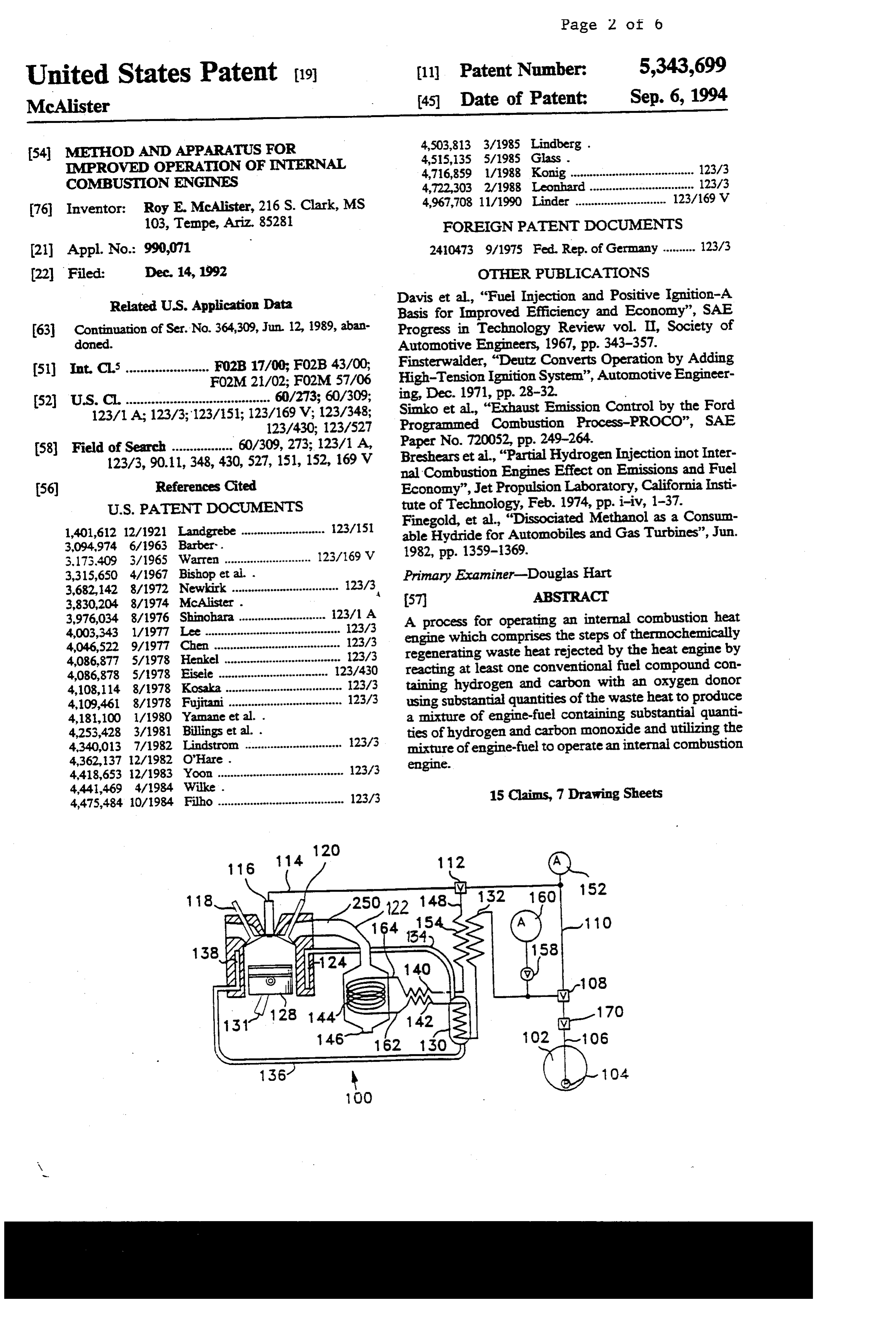
Page 22
Drawing sheet — no readable text.
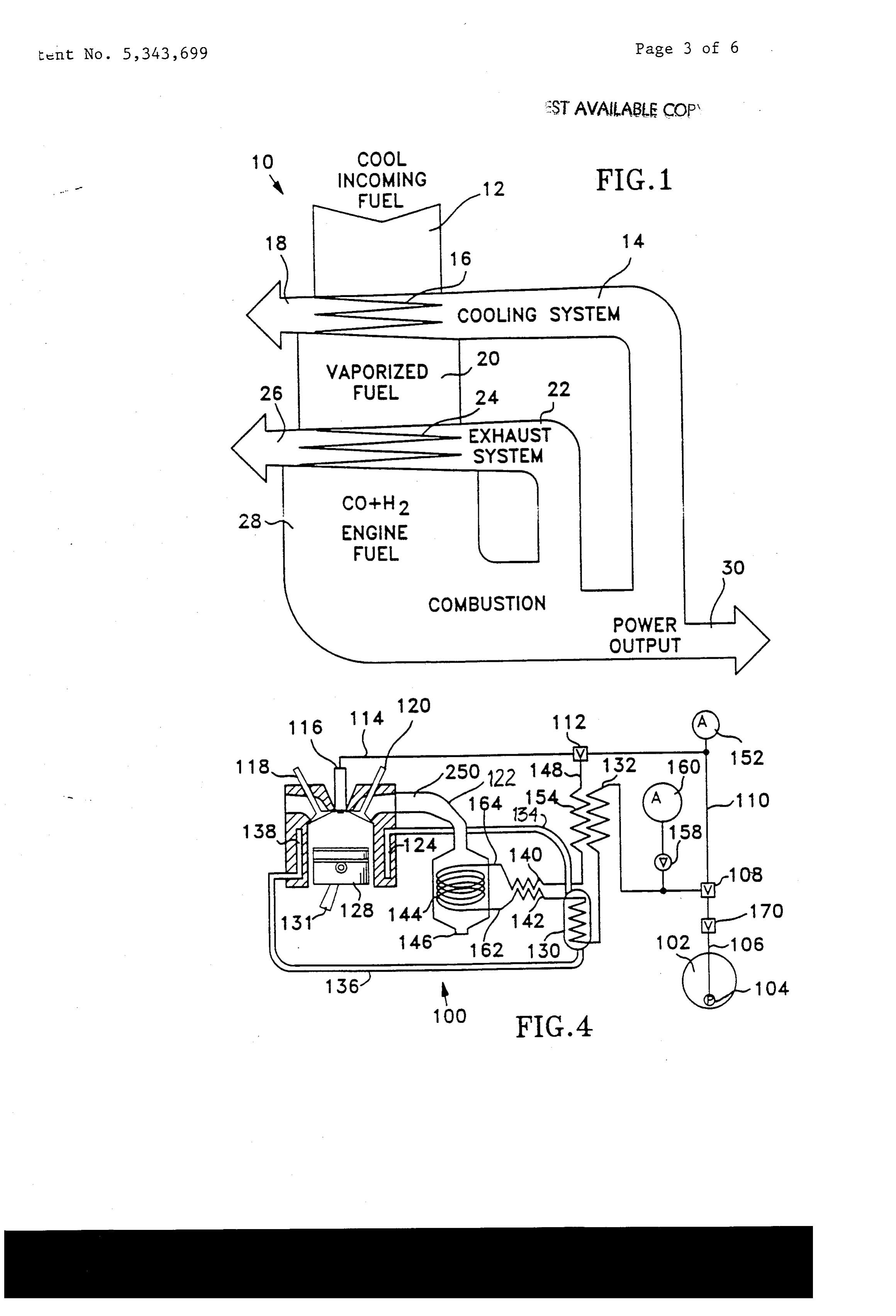
Page 23
Drawing sheet — no readable text.
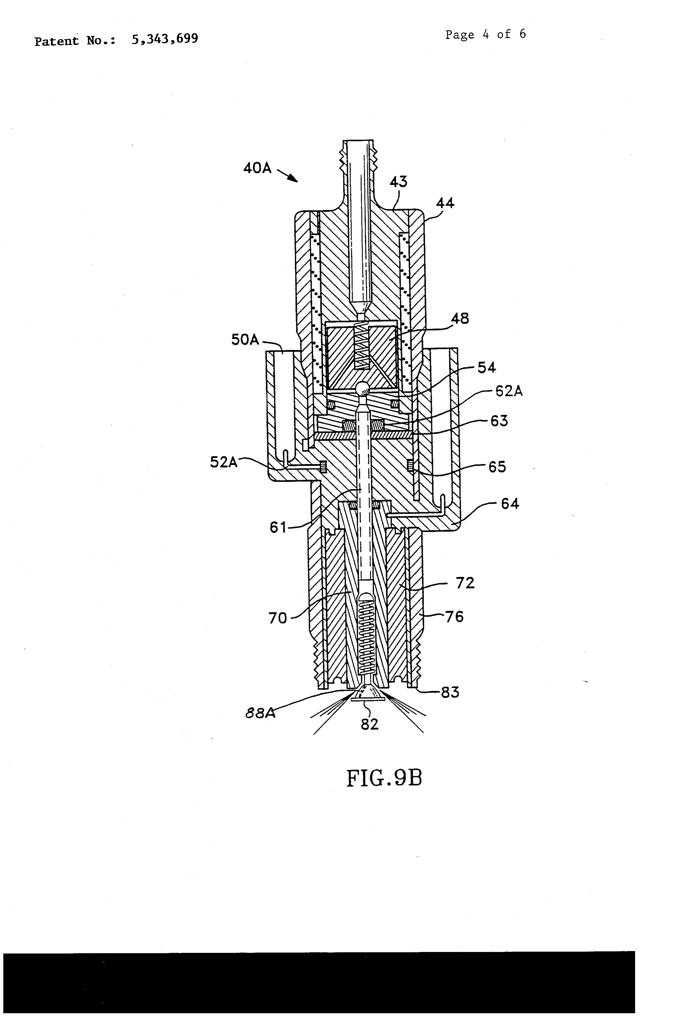
Page 24
UNITED STATES PATENT ANDTRADEMARK OFFICE
CERTIFICATE OF CORRECTION
DATED : September 6, 1994 Page 5 of 6 INVENTOR(S) : Roy E. McAlister
It is certified that error appears in the above-indentified patent and that said:lie: "...ate::::: *farery Corrected as shown belgw:
On title page item 56
In the list of "Other Publications" please correct the "inot" by replacing it with - into -in the Breshears
title and add the source for the Finegold publication which is -- Hydrogen Energy Progress els
In column 6, strike lines 43, 44, and 45.
In column 6, replace "8" in line 46 with - 7 -.
In column 6, in line 56 add the following:
-- Fig. 9A shows an embodiment of a combined fuel injector and ignition device constructed in accordance with the principles of the present invention.
Fig.9B shows another embodiment of the combined fuel injector and ignition device constructed in accordance with the principles of the invention --.
In column 9 on line 26 after "90" add -- as shown in Figures 9A and 9B
In column 12, in line 9 replace "7" with -- 6 --.
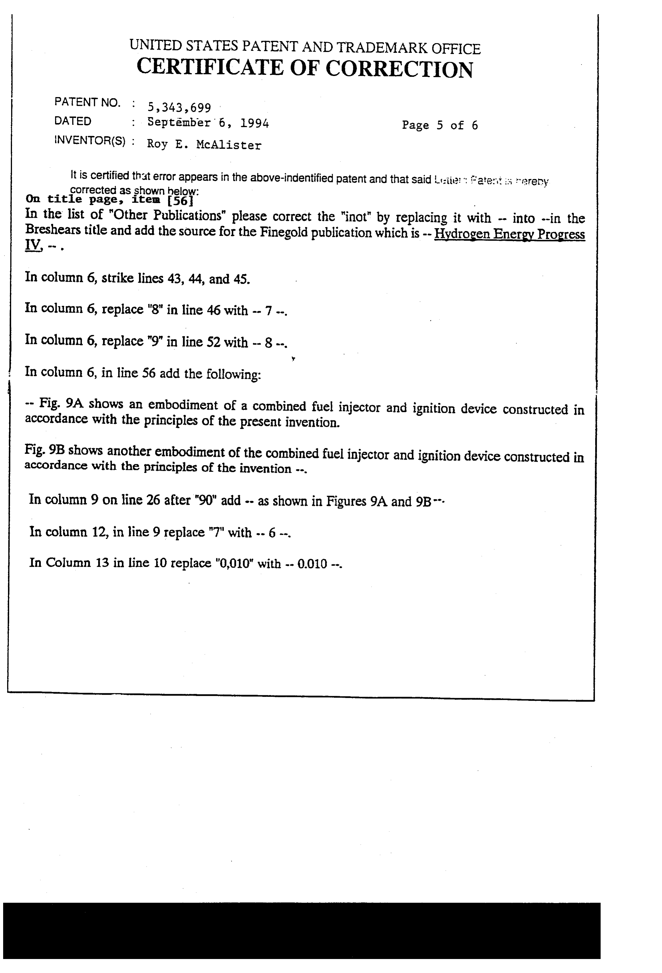
Page 25
UNITED STATES PATENT AND TRADEMARK OFFICE
CERTIFICATE OF CORRECTION
DATED : September 6, 1994 Page 6 of 6 INVENTOR(S) : Roy E. McAlister
It is certified that error appears in the above-indentified patent and that said Letters Patent is hereby Corrected as shown below:
In Column 13 in line 45 replace "177" with - 17-7PH
In Column 16 in line 60 replace "Fig. 8" with -- Figs. 5, 6, and 7 -- . In Column 17 in line 2 replace "8" with -- 7 --.
In Column 17 in line 57 do not subscript the first -- 2 -- In Column 19 in line 63 replace "9" with - 8
Signed and Sealed this
Twenty-fifth Day of April, 1995
BRUCELEHMAN
Attesting Officer Commissioner of Patents and Trademarks
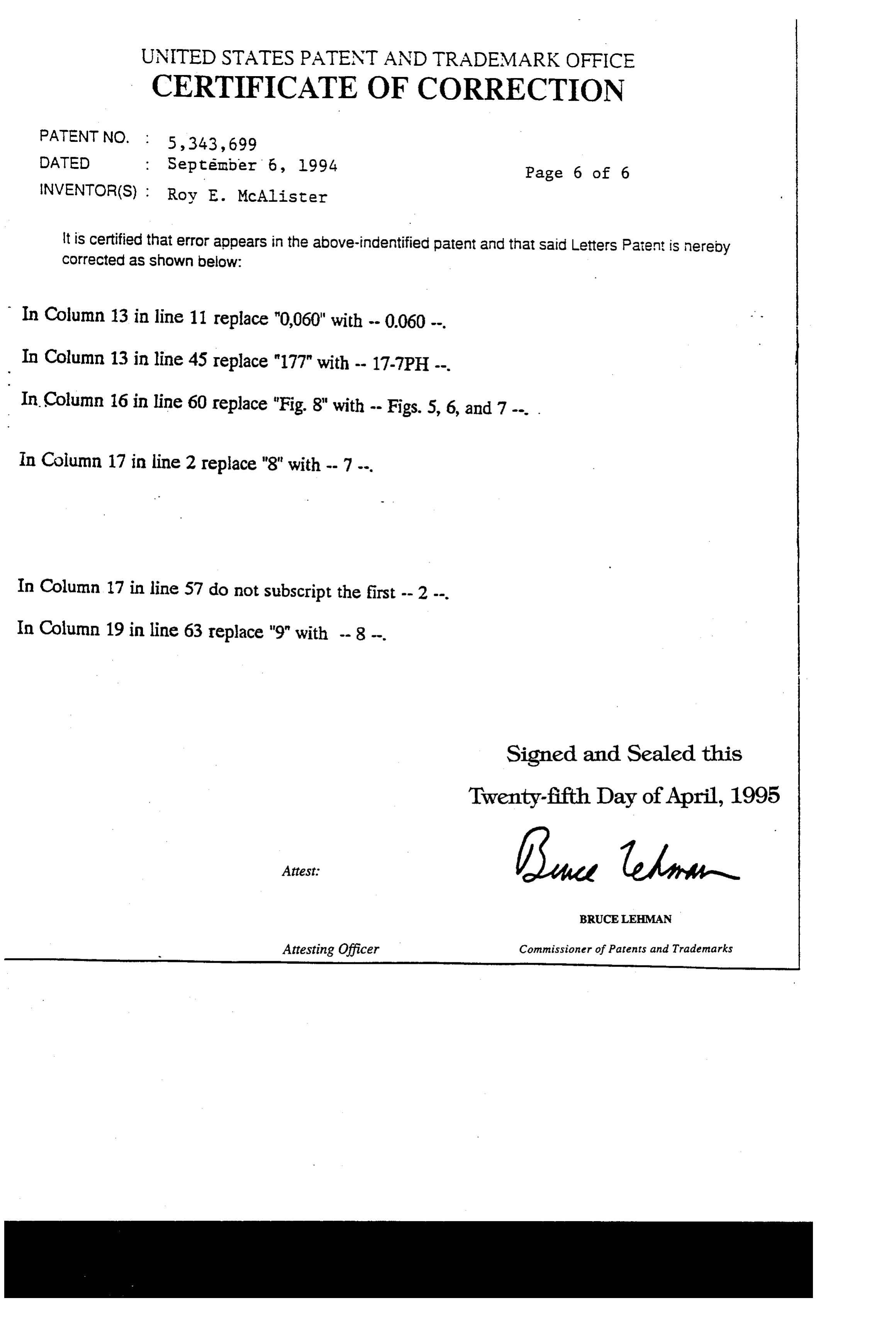
Provenance
- Collection
- Cited prior art
- Original PDF
- patentimages.storage.googleapis.com →
- Filed
- 1992-12-14
- Pages
- 25
- Method
- pdftotext (the PDF's own text layer) + pdftoppm 300dpi page scans
- Source
- Google Patents bibliographic record
- Granted
- 1994-09-06
- Inventors
- Roy E. McAlister
- Transcribed from
- patentimages.storage.googleapis.com →