patent · US3682142
Method and means for generating hydrogen and a motive source incorporating same
8 August 1972
Page 1 — bibliographic record
United States Patent (15) 3,682,142 Newkirk (45) Aug. 8, 1972 54) METHOD AND MEANS FOR 3,572,297 3/1971 Murray...................... 123/1 A GENERATING HYDROGEN AND A 3,608,660 9/1971 Smith et al................. 123/1 A
MOTIVE SOURCE INCORPORATENG
SAME Primary Examiner-Wendell E. Burns 72) Inventor: Marc S. Newkirk, Lynnfield, Mass. Attorney-Cesari & McKenna (73) Assignee: Mass.
International Materials, Lynnfield, 57 ABSTRACT
A hydrogen generation system mixes a liquid 22) Filed: May 6, 1971 hydrocarbon fuel with water and heats the mixture 21 Appl. No.: 140,858 sufficiently to thermally decompose the mixture to ob tain hydrogen gas. This gas is then fed to an internal 52 U.S. Cl............................ 123/3, 12311 A, 123/2, combustion engine capable of running on such gas. 23/21 1, 23/281 The engine generates exhaust products, consisting 51 Int. Cl......F02b 43/08, F02b 63/00, F02b 75/12 principally of water which is recycled back for mixing 58) Field of Search...... 12313, 2, 1 A, 1; 23/21 1,281 with the hydrocarbon fuel and carbon dioxide which is not considered a pollutant.
56) References Cited 20 Claims, 2 Drawing Figures
UNITED STATES PATENTS
2,152,196 3/1939 Kokatnur................... 123/1 A
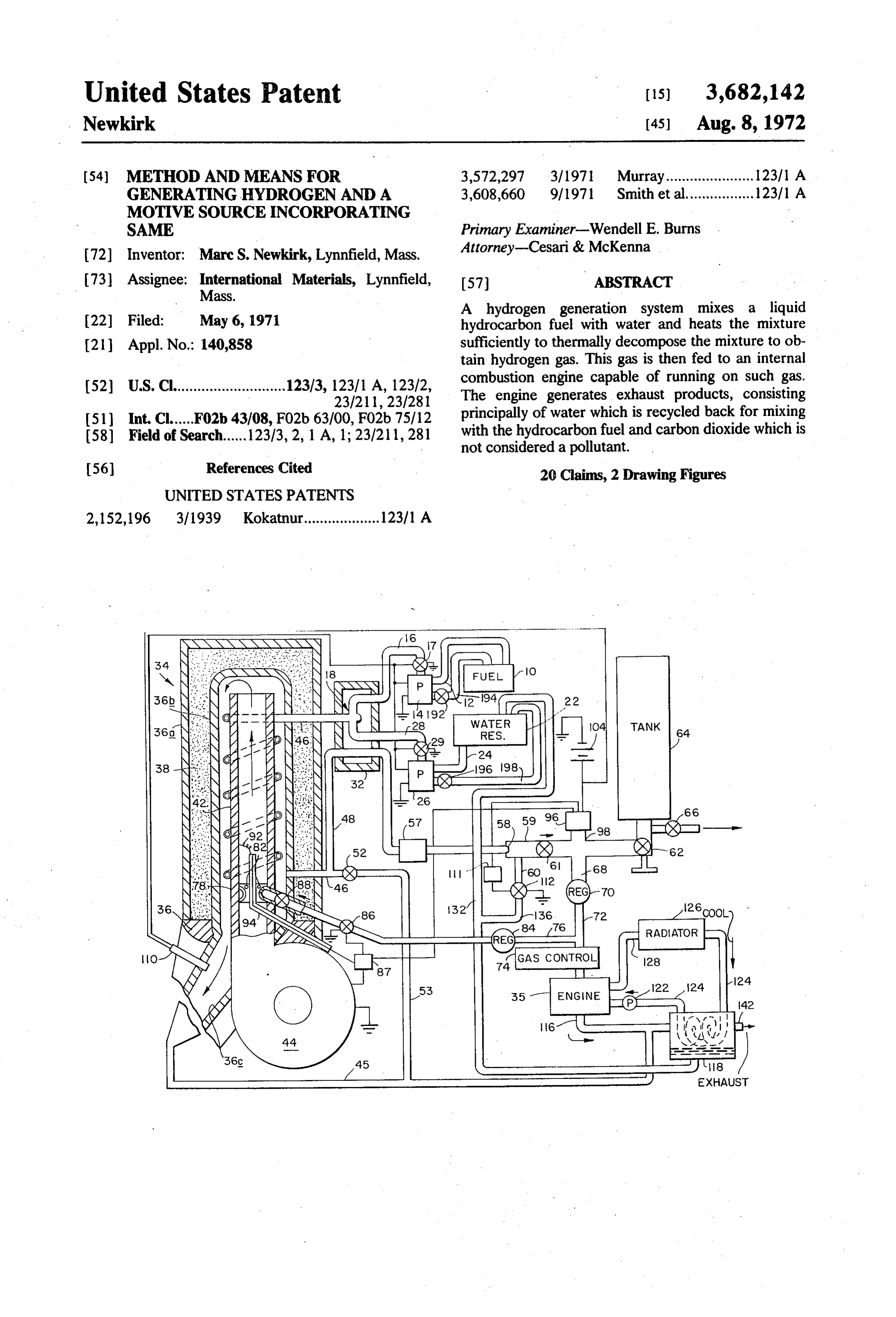
EXHAUST
Page 2
Drawing sheet — no readable text.
Page 3
Drawing sheet — no readable text.
Page 4
METHOD AND MEANSFOR GENERATING Briefly, the present system mixes a relatively inex HYDROGEN AND AMOTIVESOURCE pensive hydrocarbon fuel such as kerosene with water NCORPORATING SAME and heats the mixture in a thermal cracking unit suffi BACKGROUND OF THE INVENTION ciently to decompose the hydrocarbon to generate hydrogen gas. The hydrocarbon fuel and water are
This invention relates to a system for generating pumped into the unit using special high pressure, low hydrogen gas. It relates more particularly to a system of flow rate pumps to be described later which enable the this type which is compact and efficient enough to be unit to operate at relatively high pressure, on the order an on-board fuel source for a hydrogen fueled internal O of 1,200-1,400 psi, for maximum efficiency. Also, a combustion system. portion of the hydrogen gas generated by the unit is fed Hydrogen fueled engines are, of course, not new. back to the unit and mixed with air and ignited to People have sought to develop engines such as this develop the necessary heat to decompose the hydrocar because of the very low amount of pollutants which the bon.
engines emit. That is, the primary exhaust product of 15 The major portion of the gas produced by the hydrogen combustion is water vapor which does not cracking unit is stored under high pressure in a tank so contaminate the atmosphere. that a supply of fuel is always available for use by an as The utilization of a hydrogen fueled engine to power sociated engine. Consequently, the cracking unit does an automobile or other vehicle requires that a source of not have to operate continuously while the engine is hydrogen be maintained on the vehicle itself. Conven- 20 running. Rather, it operates only when the gas pressure tionally, this has been done by storing a quantity of in the system falls below the determined amount, e.g. hydrogen gas under pressure in a tank carried by the 1,200 psi.
vehicle. Obviously, that fuel source has its limitations The gaseous fuel is conducted as needed from the since the supply of gas is exhausted relatively quickly. It tank to an internal combustion engine which is capable has also been proposed to store a quantity of hydrogen 25 of running on hydrogen gas. A suitable engine of this in liquid form. However, this requires the utilization of type is disclosed in copending application Ser. No. a cryogenic tank or the like which is relatively bulky 47,990, filed June 22, 1970, entitled Gas Fueled Inter and quite expensive to make. Also, the amount of nal Combustion Engine. The engine exhaust is com hydrogen that can be stored in this fashion is still rela prised primarily of high energy steam, the major por tively limited. It has also been suggested to generate the 30 tion of which is condensed and pumped to a tank to hydrogen right on the vehicle either by electrolysis or provide a supply of water for mixing with the kerosene by chemical means. However, attempts such as this fuel. This further increases the overall efficiency and have not met with much success principally because of performance of the system.
the expense, but also because the amount of hydrogen Provision is also made for preventing excessive build that can be generated as a function of time for a 35 up of pressure in the system and for automatically sustained period is relatively small. shutting the cracking unit offin the event of a malfunc
SUMMARY OF THE INVENTION
tion. All of these factors make the present system espe cially safe and reliable for use as a self-contained mo
Accordingly, it is an object of the present invention 40 tive source for land, sea and air vehicles, for heating to provide a system for generating hydrogen gas which for and generating plants and as a source of hydrogen gas is compact and efficient enough to be carried on board aerospace applications, fuel cells and the like. a hydrogen fueled vehicle. BRIEF DESCRIPTION OF THE DRAWINGS Another object of the invention is to provide a system for generating hydrogen gas used to power an 45 For a fuller understanding of the nature and objects associated motive source. of the invention, reference should be had to the follow Yet another object of the invention is to provide a ing detailed description taken in connection with the system for generating hydrogen gas from a relatively in accompanying drawings, in which:
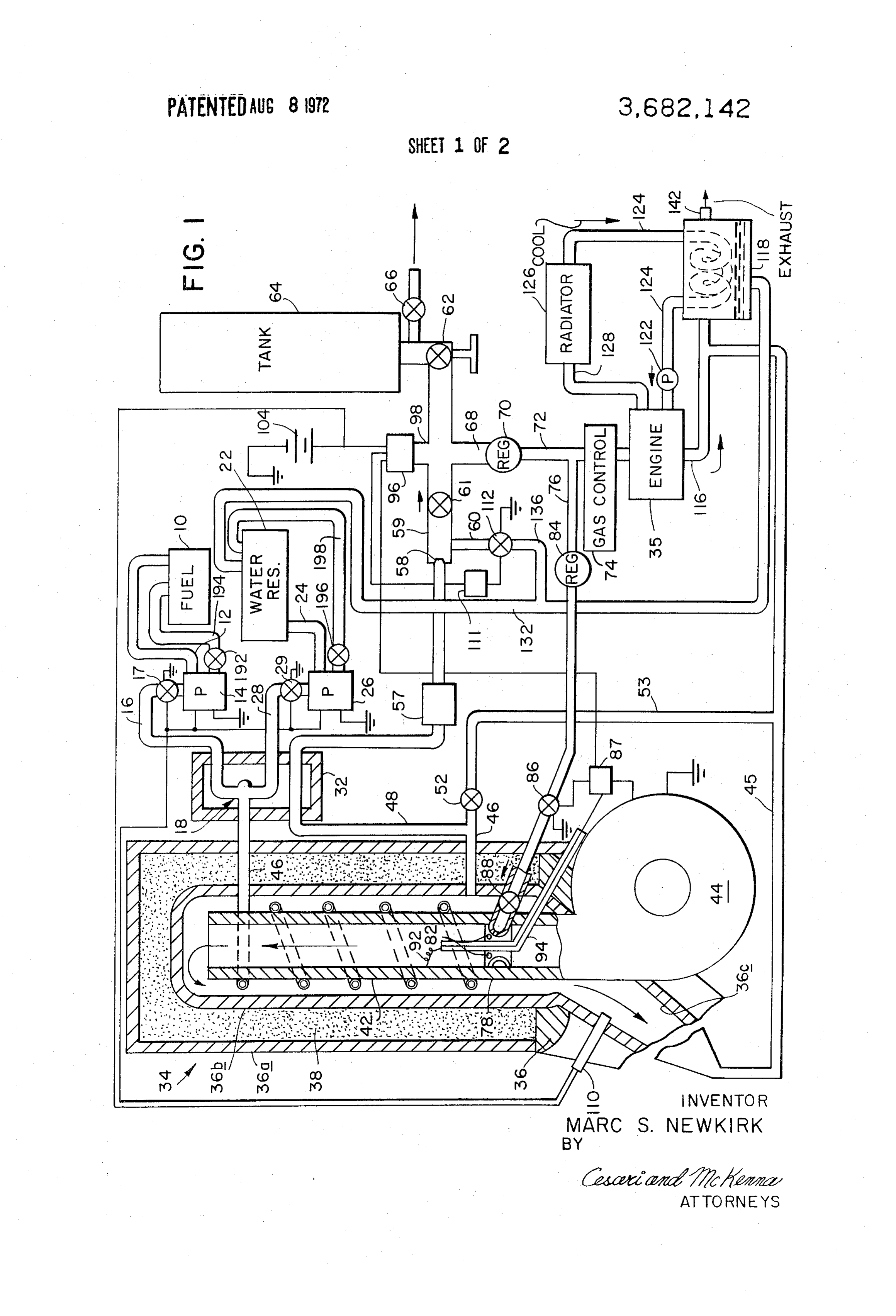
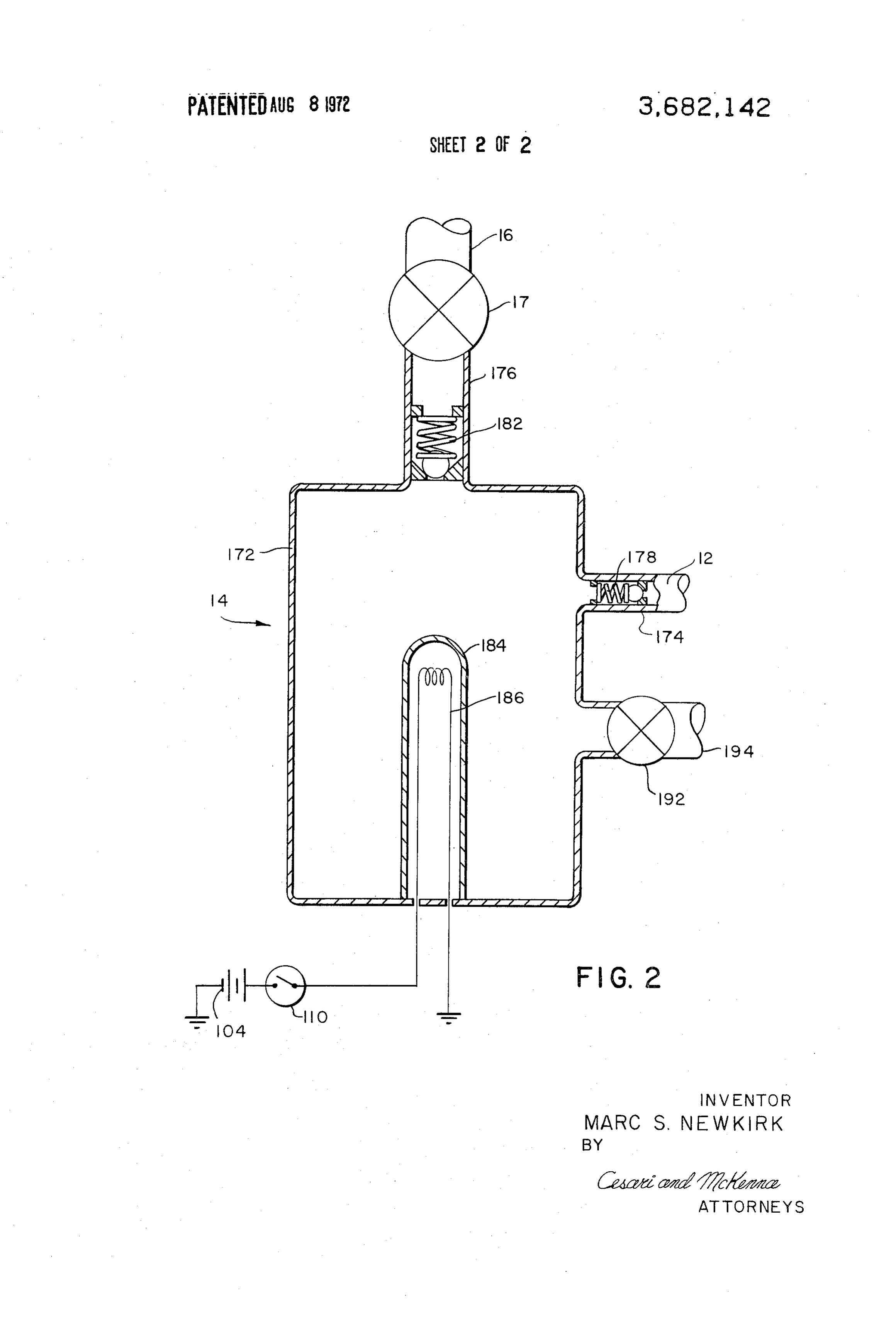
expensive hydrocarbon fuel. FIG. 1 is a diagrammatic view of a hydrogen genera Another object is to provide a system for generating 50 tion system embodying the principles of our invention; hydrogen gas for an internal combustion engine which and uses the engine's exhaust products in the hydrogen FIG. 2 is a view in medial section of a high pressure, generation process. low flow rate pump used in our system. A further object of the invention is to provide a DESCRIPTION OF THE PREFERRED hydrogen fueled engine having a self-contained 55 EMBODEMENT hydrogen source.
Another object of the invention is to provide a Turning now to FIG. 1 of the drawings, a relatively system for generating hydrogen which is relatively reli low-priced, easily available liquid fuel such as kerosene able and safe. is stored in tank 10. A conduit 12 conducts the fuel Other objects will in part be obvious and will in part 60 from tank 10 to a special high pressure, low volume appear hereinafter. pump 14 to be described in more detail later. The fuel The invention accordingly comprises the others and is then pumped through a conduit 16 including a sole the apparatus embodying the features of construction, noid-operated valve 17 to a mixing chamber 18 where combination of elements and arrangement of parts all it is thoroughly mixed with water. This water is supplied as exemplified in the following detailed disclosure, and 65 from a water reservoir 22 by way of a conduit 24 con the scope of the invention will be indicated in the taining a pump 26 similar to pump 14. Pump 26 pumps claims. the water at high pressure through conduit 28 contain
Page 5
ing a solenoid valve 29 to chamber 18 where it mixes storage tank 64. Valve 61 permits gases to flow toward with the fuel. Chamber 18 is located in a heat tank 64, but not in the opposite direction. Valve 62 is exchanger 32 so that the incoming fuel-water mixture is included in the event that it is desired to isolate tank 64 heated prior to entering a cracking unit shown when the system is being repaired. Also, tank 64 in generally at 34. Unit 34 generates sufficient hydrogen cludes the usual pressure relief valve 66 for safety gas to supply the needs of an internal combustion en reasons. This valve is set to relieve at a higher pressure gine 35 such as the one disclosed in the aforesaid pend than valve 52, e.g., 3,300 psi, and gases issuing from ing application. valve 66 may be disposed of in the same way as those Cracking unit 34 comprises an insulated housing 36 from valve 52, if desired. Since the gases are cooled as having a generally rectangular outer wall 36a and a 0 justmentioned, a maximum supply of fuel can be main generally cylindrical inner wall36b. The space between tained in tank 64 at the desired pressure. the two walls is filled with a suitable nonflammable in A conduit 68 connected to conduit 59 downstream sulating material 38. Situated inside housing 36 is an from check valve 61 leads the hydrogen and carbon open-ended tube 42. The lower end of tube 42 con 15 dioxide gases to a pressure regulator 70 that reduces nects to the outlet of a relatively powerful centrifugal the gas pressure to about 50 to 200 psi which is suitable blower 44 while the upper end of tube 42 is spaced for the engine. Another conduit 72 conducts the gases from the end of the housing wall 36b. When blower 44 from the regulator 70 to engine 35 by way of a gas con is operating, air is forced up through the tube 42 exiting trol system 74. System 74 controls the feeding of gas to through the upper end thereof and passing down 20 the engine when the engine is turned on and the throt through the space between tube 42 and the inside wall tle is moved to its various positions of adjustment. Such 36b of housing 36. The lower end of the housing 36 a system is disclosed in the copending application opens into an exhaust manifold 36c which may be con noted above.
nected by a conduit 45 to the engine 35 exhaust as will Conduit 72 also includes a branch line 76 ahead of be described later. 25 the gas control system 74. Line 76 conducts a portion The fuel-water mixture from chamber 18 is con of the hydrogen gas back to the cracking unit 34 where ducted via a conduit 46 into housing 36. The portion of it is mixed with air from blower 44 and ignited to supply conduit 46 inside the housing is wound in spiral fashion the heat for the unit. More particularly, a toroidal tightly around the tube 42, exiting the housing near the manifold 78 is situated inside tube 42 near the bottom lower end thereof. As the fuel-water mixture travels 30 thereof. This manifold has a number of openings 82 through conduit 46 inside unit 34, it is heated to a tem spaced around its inside wall. The conduit 76 extends perature in excess of 1,500 F. which is sufficient to through the housing walls 36a and 36b and the tube 42 vaporize the fuel and water and to thermally decom and communicates with the interior of manifold 78. pose the hydrocarbon-water mixture to hydrogen gas, 35 A pressure regulator 84 included in conduit 76 me water vapor and carbon dioxide, although minor ters the proper amount of gas to the manifold to create amounts of carbon monoxide and uncracked hydrocar with the air from blower 44 a highly combustible gas bon may also be present. air mixture. Also, a solenoid-operated valve 86 is in These hot gases are then conducted via a conduit 48 cluded in conduit 76 downstream from the regulator connected to conduit 46 through the heat exchanger 40 84. This valve is open only when the cracking unit 34 is 32, where they give up some of their heat to the incom in operation, as will be described in more detail later. ing fuel-water mixture and are cooled in the process. A Finally, a check valve 88 in conduit 76 just ahead of relief valve 52 provided at the junction of conduits 46 manifold 78 allows gas to flow into the manifold, but and 48 prevents the buildup of excessive pressures in not in the opposite direction. This is to prevent the buil the cracking unit 34, e.g. 1,500 psi. Also, to avoid re 45 dup of an explosive mixture inside the conduits. lieving these flammable gases directly to the at The gas-air mixture inside tube 42 is ignited at the mosphere, they may be fed through a conduit 53 into proper time by means of a hot filament wire 92 posi conduit 45 and thence to the engine exhaust, being tioned just above manifold 78. One end of wire 92 is diluted with engine exhaust products well below com connected to tube 42 which constitutes an electrical bustible mixtures. 50 ground, the other end of the wire is led out of the The cracked product from unit 34 is conducted from cracking unit through an insulating tube 94 which ex the heat exchanger 32 through a filter 57 and then ex tends down through manifold 78 and out through panded through an orifice 58 at the end of conduit 48 openings in tube 42 and housing walls 36a and 36b. Hot into a larger diameter conduit 59. Upon expansion wire 92 is connected in series electrically with a time through the orifice, the hot vapors and gases are cooled 55 delay relay 87, a pressure switch 96 responsive to the even more with the result that a large percentage of the pressure in a stub branch 98 of conduit 59 and a con steam content thereof is condensed to water. This ventional current source, illustratively a battery 104. water is removed by means of a steam trap 60 in con On the other hand, blower 44 is connected in parallel duit 59 just beyond restriction 58. Thus, the output of 60 with valve 86 and hot wire 92. Switch 96 closes only the generation system is primarily hydrogen and carbon when the pressure in conduit 59 (and tank 64) drops dioxide gases. The latter gas is inert and does not inter below the 1,200 psi normal operating pressure of the fere with the combustion of hydrogen in engine 35. In system. It remains closed until the pressure exceeds a fact, it acts as an expansion medium during the com selected value higher than 1,200 psi, e.g., 1,350 psi. bustion process so that engine efficiency is increased 65 Pressure switches having this operating "spread" are somewhat. commercially available.
Conduit 59 conducts the gases by way of a check When switch 96 closes, hot wire 92 begins to heat valve 61 and a shutoff valve 62 to a temporary gas and time-delay relay 87 begins to operate. After a short
Page 6
S 6 period of, for example, 5 seconds, time-delay relay 87 The system is designed in such a manner that pres actuates solenoid valve 86, allowing gas to flow across sure will be maintained in the tank 64 of at least 1,200 hot wire 92 where it is ignited. At the same time, psi regardless of engine operation. Naturally, an empty blower 44 is actuated by time-delay relay 87 and begins tank 64 would have to be charged initially with gas in to blow air through tube 42. After the solenoid valve 86 order to heat unit 34 for the first time. opens and blower 44 begins to operate, time-delay Pressure switch 96 is of a dual contact type. One set relay 87 turns off the hot wire 92 in order to conserve of contacts opens with rising pressure and closes with battery strength. Time-delay relay 87 is connected in falling pressure. This set of contacts is connected to series with hot wire 92 in such a manner that should hot 10 time-delay relay 87. A second set of contacts in switch wire 92 fail, the time-delay circuit would open, 96 closes with rising pressure and opens with falling preventing any flow of fuel through solenoid valve 86. pressure. This set of contacts is connected in series with The heat of combustion of the gas-air mixture in tube a time-delay relay 111 and a solenoid valve 112. When 42 is sufficient to heat tube 42 and the conduit wound the gas pressure in conduit 98 exceeds the desired around it to the preferred cracking temperature. 15 1,350 psi, the first set of contacts in switch 96 opens, Since the combustion inside tube 42 is not normally thereby shutting off the cracking unit 34 at the same entirely confined, it proceeds relatively efficiently so time. The second set of points closes, energizing sole that the combustion products are, for the most part, noid valve 112 and time-delay relay 111. Time-delay water vapor, although there will be some carbon diox relay 111 is of a type that allows solenoid valve 112 to ide and a small amount of unburned hydrocarbons as 20 open only for a brief period, for example, one second, well. Thus, even if these combustion products are to allow water to be expelled under pressure from trap released directly to the atmosphere, they cause a 60. After the desired brief period, the time-delay relay minimal amount of pollution. closes valve 112. When the pressure in conduit 98 The cracking unit 34 continues to generate hydrogen 25 again falls below the desired 1,200 psi pressure, the gas until the pressure in conduit 56 exceeds 1,350 psi. second set of contacts in switch96 will open and time Whereupon, blower 44 stops and solenoid valve 86 delay relay 111 will return to the beginning of its cycle. Inside engine 35, the hydrogen gas is mixed with air closes, thereby shutting off unit 34.
Still referring to FIG. 1, steps are taken to insure that waterconsumed and vapor with the carbon dioxide and residual acting as an expansion medium. The prin the cracking unit 34 is heated sufficiently to thermally 30 decompose the hydrocarbon before the fuel-water mix energy steam and carbonofdioxide.
cipal exhaust products the engine are therefore high ture is allowed to enter the cracking unit. This is to An exhaust manifold 16 conducts the exhaust prevent uncracked fuel from passing through the unit products and on into the associated engine 35. More particu where thefrom the engine 35 to a heat exchanger 118 larly, a heat-responsive switch 110 is installed in ex 35 and condensed energy high steam in the exhaust is cooled by the water in the engine's cooling haust manifold 36c. Switch i10 is in a series-parallel system. More particularly, the engine's water pump circuit with battery 104 and pumps 14 and 26 so that it 122 pumps cooling fluid through the engine and thence controls the operation of these pumps. Only when the through hose 128 to the automobile cracking unit 34 is heated to a temperature sufficient to Another conduit 124 carries the cooling radiator fluid in a
cir crack the incoming fuel-water mixture will switch 110 40 cuitous path through the heat exchanger 118 and turn on pumps 14 and 26. Further, in the event that the thence back to water pump 122. The radiator 126 flame inside tube 42 fails, the temperature of the unit will quickly drop, causing switch 110 to shut off pumps system has sufficient cooling capacity to cool both the engine and the exhaust gases in heat exchanger 118.
14 and 26, thereby stopping the flow of liquid into the 45 The water condensed in heat exchanger 118 is con cracking unit.
When the generation system is used in a vehicle, as il ducted
back to water reservoir 22 by way of return line
Thus, a large part of the water content in the ex lustrated, tank 64 contains a supply of hydrogen gas so haust is recycled to crack additional hydrocarbon fuel. that the engine 35 can be started and run for a time on This minimizes the necessity of replenishing the water the gas already contained in tank 64. As soon as the 50 supply carried by the vehicle. Also, the water obtained pressure in the tank drops below 1,200 psi, however, the pressure switch 96 will close, thereby energizing from trap 60 in the manner described above may be conducted back to reservoir 22 by means of the con hot wire 92 and time-delay relay 87 to ignite the com duit 136 extending from the outlet of valve 112 to con bustible mixture formed inside tube 42. Then when the duit 32. In addition, as noted previously, the exhaust temperature of the cracking unit 34 heats to the desired 55 products from the cracking unit 34 may be conducted temperature, i.e., in excess of 1,500 F., switch 110 by conduit 45 to the engine 35 exhaust and the steam closes, thereby allowing the fuel-water mixture to enter content thereof condensed in the heat exchanger 118 the cracking unit. The unit thermally decomposes the to provide even more water.
liquid to generate more gaseous fuel at high pressure With the water in the engine exhaust being removed which refills the tank 64 until the gas pressure therein 60 as aforesaid, the principal exhaust product issuing from exceeds the desired 1,350 psi value. At this point, heat exchanger 118 through the exhaust pipe 42 is switch96 opens, thereby shutting off the cracking unit carbon dioxide which is not considered a pollutant. 34. The system remains off until the next time the gas There may also be a minor amount of unburned pressure drops below 1,200 psi. Thus, the hydrogen hydrocarbons and carbon monoxide which are pollu generation system cycles on and off to meet the de 65 tants, although the amounts involved are far less than mands of the engine or other device consuming the would be the case with a conventional internal com hydrogen produced by the system. bustion engine burning a liquid hydrocarbon or a gas
Page 7
such as propane or natural gas. Moreover, the present The decomposition of other hydrocarbon fuels in system produces essentially no nitrogen oxides which cluding kerosene yields similar results. are especially harmful contaminants. Turning now to FIG. 2, since the thermal decomposi By controlling the proportions of water and fuel en tion process occurs at high pressure, on the order of tering the cracking unit 34, and the cracking tempera 1,200-1,350 psi, special high pressure, low flow rate ture, one may control to some extent the output of that electric pumps 14 and 26 are used to pump the liquids unit. More particularly, we have found that if there is into the cracking unit 34. These pumps have no moving an excess of water at a temperature of about 1,050 C., parts (except check valves) and are quite simple. Since the unit 34 output consists almost entirely of hydrogen the two pumps are identical, we will describe only gas, carbon dioxide gas and steam. These products are O pump 14 in detail.
not considered pollutants. Consequently, when the en Pump 14 comprises astrong, rigid housing 172 which gine 35 is run on these compounds, the engine exhaust is made of high tensile strength steel or equivalent is substantially pollution-free, even if the engine is not material. Housing 172 has an inlet 174 in its side wall tuned properly. On the other hand, if less water is used 15 which is connected to conduit 12 and an outlet 176 in and the input liquid heated to 700°C., the output of the its top wall which is connected to conduit 16. Conven cracking unit consists primarily of hydrogen gas and tional ball check valves 178 and 182 are situated in carbon monoxide. Finally, if no water at all is mixed inlet 174 and outlet 176, respectively. Valve 178 allows with the incoming fuel and the unit is maintained at a fluid to flow into housing 172 but not in the opposite temperature of approximately 1,000 C., then the ther 20 direction, while valve 182 allows fluid to flow only out mal decomposition products are primarily hydrogen of the housing.
gas and carbon. Obviously, for engine applications, the An upstanding tube 184 which is closed at its upper cracking unit 34 should ideally be controlled so that the end is welded to the bottom wall inside housing 172. decomposition products are, for the most part, the non This tube contains a Nichrome heating element 186 pollutant compounds of hydrogen, carbon dioxide and 25 whose leads extend through insulated openings in the Water. bottom wall of the housing. The element 186 is con The efficiency of the thermal decomposition process nected electrically with the battery 104 and heat can be improved even more by employing a catalyst in responsive switch 110.
the cracking unit, a suitable catalyst being alumina Assuming that housing 172 is filled with liquid (fuel grains with tungsten or molybdenum oxide surface 30 or water), when the heating element 186 is energized, it coatings. Also, particularly in the case where a catalyst heats up the contents of the housing, causing a slight is used, the exhaust products issuing from exhaust pipe expansion of the liquid. Thus, some of the liquid is 142 which are still rather hot can be routed back to the forced out through the outlet 176. On the other hand, cracking unit 34 to help heat the incoming fuel-water when the heating element 186 is deemergized, the liquid mixture before being expelled to the atmosphere. 35 in the housing cools and contracts to some extent, Other modifications of the present system suggest thereby developing a vacuum in the housing and draw themselves to improve its operation in particular appli ing additional liquid into the housing through its inlet cations. For example, the presence of carbon dioxide in 174.
the output of the cracking unit 34 may be undesirable Thus, each time the heating element 186 is turned in certain instances. In this event, that gas may be 40 on, additional liquid is pumped out through the valve separated from the hydrogen gas by means of a cen outlet 176 and each time the element is deemergized, trifugal separator or other similar device which is capa more liquid is drawn through the inlet 174. Con ble of separating these gases. sequently, the pump 14 may be cycled on and off con It is believed that the steam reformation of a tinuously, so as to pump liquid toward the cracking unit hydrocarbon fuel such as heptane (CH) proceeds in 45 34 (FIG. 1). Actually, a pump 14 operating over a tem accordance with the following equation: perature gradient of only 10-30 F. is able to develop CH-14H.0 - 7C0+22H very high pressures, on the order of 50,000 psi. This breaks down into the following equations: Further, the flow rate of the pump can be controlled somewhat by regulating the rate at which the heater 50 186 is cycled on and off by switch 110. Pumps 14 and
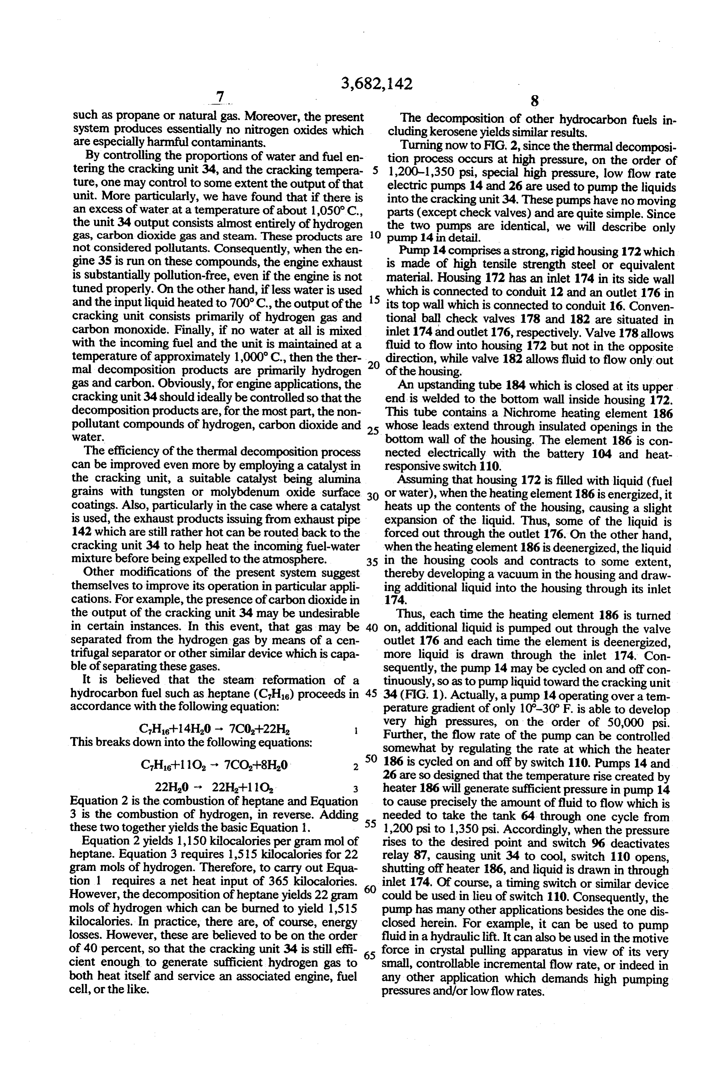
26 are so designed that the temperature rise created by heater 186 will generate sufficient pressure in pump 14
Equation 2 is the combustion of heptane and Equation to cause precisely the amount of fluid to flow which is 3 is the combustion of hydrogen, in reverse. Adding 55 needed to take the tank 64 through one cycle from these two together yields the basic Equation 1. 1,200 psi to 1,350 psi. Accordingly, when the pressure Equation 2 yields 1,150 kilocalories per gram mol of rises to the desired point and switch 96 deactivates heptane. Equation 3 requires 1,515 kilocalories for 22 relay 87, causing unit 34 to cool, switch 110 opens, gram mols of hydrogen. Therefore, to carry out Equa shutting off heater 186, and liquid is drawn in through tion 1 requires a net heat input of 365 kilocalories. inlet 174. Of course, a timing switch or similar device However, the decomposition of heptane yields 22 gram 60 could be used in lieu of switch 110. Consequently, the mols of hydrogen which can be burned to yield 1,515 pump has many other applications besides the one dis kilocalories. In practice, there are, of course, energy closed herein. For example, it can be used to pump losses. However, these are believed to be on the order fluid in a hydraulic lift. It can also be used in the motive of 40 percent, so that the cracking unit 34 is still effi 65 force in crystal pulling apparatus in view of its very cient enough to generate sufficient hydrogen gas to small, controllable incremental flow rate, or indeed in both heat itself and service an associated engine, fuel any other application which demands high pumping cell, or the like. pressures and/or low flow rates.
Page 8
The rise in ambient temperature could, of course, water together prior to their being thermally decom cause an increase in pressure within pump 14. In order posed.
to control this pressure and prevent undesired leakage 5. The motive source defined in claim 4 and further into the system, the solenoid valve 17 is provided in including a heat exchanger for preheating the conduit 16. This valve 17 is connected in parallel with hydrocarbon fuel and water prior to their decomposi heater 186 so that fuel flows out of the pump only when tion, the pumps are operating. Further, in order to prevent 6. The motive source defined in claim 5 wherein the undue pressure buildup in the system, a pressure relief thermal decomposition products are conducted valve 192 is provided in the pump housing 172 which through the heat exchanger to preheat the incoming opens at an appropriate pressure, e.g. 1,400 psi and al- 10 fuel and water.
lows liquid to be returned to storage tank 10 by way of 7. The motive source defined in claim 1 wherein the a conduit 194. fuel and water sources include high pressure, low volu The pump 26 operates in the same way with its sole metric flow rate pumps which maintain the fluids in the noid outlet valve 29 operating in unison with valve 17. 15 conduit under relatively high pressure during the decomposition process.
Also, it has a pressure relief valve 196 in a return line 198 leading back to reservoir 22 which operates like 8. The motive source defined in claim 7 and further valve 192 associated with pump 14. including a tank communicating with the conduit It is apparent from the foregoing then that the ahead of the engine for temporarily storing hydrogen present system which thermally decomposes hydrocar 20 gas generated during the thermal decomposition bon fuels using a steam reformation process is a par process so that such gas will be available immediately ticularly compact, reliable and efficient source of to 9.meet The the demands of the engine.
motive source defined in claim 8 wherein the hydrogen gas. Further, when combined with an engine conduit includes capable of running on such gas, an especially desirable and the engine which a pressure regulator between the tank motive source is produced which has many varied ap the gas being fed to thereduces
engine.
the gas pressure prior to plications in the automotive, marine and aerospace in 10. The motive source defined in claim 8 and further dustries.
It will thus be seen that the objects set forth above, including among those made apparent from the preceding 30 A.generated means in the conduit for condensing steam during the thermal decomposition description, are efficiently attained and, since certain process prior to its reaching the tank and the en changes may be made in the construction set forth gine, and without departing from the scope of the invention, it is B. means for removing the condensate from the con intended that all matter contained in the above descrip tion, or shown in the accompanying drawings, be in 35 11.duit. The motive source defined in claim 10 wherein terpreted as illustrative and not in a limiting sense.
It is also to be understood that the following claims and the removingmeans the condensing means includes an expansion chamber comprises are intended to cover all of the generic and specific fea A. atrap, and tures of the invention herein described. B. means for conducting the condensate from the I claim: 40 trap to the water source at predetermined times. 1. A hydrogen powered motive source comprising 12. The motive source defined in claim and further A. a source of hydrocarbon fuel, including means for controlling the operation of the B. a source of water, heating means so as to maintain the pressure of the gas C. an internal combustion engine, in the conduit above a selected minimum value. D. a conduit connecting the fuel and water sources 45 13. The motive source defined in claim 3 wherein and the engine, and A. the engine includes a cooling system, and E. means for heating the conduit to a temperature B. the condensing means is coupled to the cooling sufficient to thermally decompose the fuel-water system and cooled thereby.
mixture to hydrogen which is then conducted to 14. The motive source defined in claim 7 wherein the engine and consumed in the internal com 50 each pump comprises bustion process. A. afluidtighthousing, 2. The motive source defined in claim 1 and further B. an inlet containing a check valve, including C. an outlet containing a check valve, and A. means for conducting a portion of the hydrogen D. means for heating the contents of the housing at gas being fed to the engine back to the conduit 55 selected time intervals.
heating means, and 15. The motive source defined in claim 1 and further B. means in the heating means for igniting the including means for preventing flow of fuel and water hydrogen gas conducted thereto in the presence of through the conduit unless the heating means is heated Oxygen. to a selected temperature sufficient to thermally 3. The motive source defined in claim 1 and further 60 decompose the fuel and water mixture. including 16. The motive source defined in claim 1 wherein A. means for condensing steam in the engine ex A. the heating means comprises haust, and 1 aheat exchange element,
B. means for conducting condensate back to the 65 2 means for flowing air by the heat exchange ele Water SOurce. ment, 4. The motive source defined in claim 1 and further 3 means for flowing a gas by the element so as to including means for mixing the hydrocarbon fuel and create with the air a combustible mixture,
Page 9
4 means for igniting the mixture at selected time the airflowing means, the gas flowing means and the ig intervals to heat the element, and niting means so as to heat the element and conduit
the conduit is arranged in intimate heat exchange with the element so that when the air-gas when the gas pressure in the conduit falls below a predetermined value.
mixture is ignited, sufficient heat is generated to 5 19. The motive source defined in claim 1 and further the mally decompose the fuel and owater contained
including a catalyst inside the conduit and exposed to the fuel and water mixture therein.
17. The motive source defined in claim 16 wherein a 20. The motive source defined in claim 19 wherein portion w of the hydrogen gas generated in the conduit the catalysti 4. grains having a sur ystis comprised of alumina during thegas to supply thermal to heatdecomposition the element. process is tapped off 10 face coating selected of the group consisting of tung is the motive source defined in claim 16 and sten and molybdenum oxide. further including means for controlling the operation of xk k xk k k
Provenance
- Collection
- Cited prior art
- Original PDF
- patentimages.storage.googleapis.com →
- Filed
- 1971-05-06
- Pages
- 9
- Method
- pdftotext (the PDF's own text layer) + pdftoppm 300dpi page scans
- Source
- Google Patents bibliographic record
- Granted
- 1972-08-08
- Inventors
- Marc S Newkirk; INTERN MATERIALS
- Transcribed from
- patentimages.storage.googleapis.com →