patent · US3976034
Method for producing a combustible gas by partial oxidation for use in internal combustion engines
24 August 1976
Page 1 — bibliographic record
United States Patent 19 ( 11) 3,976,034 Shinohara et al. (45) Aug. 24, 1976 54 METHOD FOR PRODUCING A 220 1965 5/1940 Cook........................... 23f 9 E X COMBUSTBLE GAS BY PARTAL 2,295,209 9/1942 Guiles et al......................... 123/3 X OX DATION FOR USE IN INTERNAL 2,759,805 8/1956 Erickson et al................... 48/22 X COMBUSTION ENGINES 3.47 1274 0/1969 Quigley, Jr. et al......... 123/19 E X 3,717, 29 2/973 Fox ...................... ... 237 9 E X 75 Inventors: Hiroshi Shinohara, Okazaki; 3,828,736 8/974 Koch....................................... |2373 Kunihiko Masunaga, Toyota; 3,849,087 1 1/1974 Arakawa ct al... 48/23 X Toshihito Kondo, Toyota; Kazuhiko 3.87,838 3/1975 Henkel et al....................... 23/3 X Ishiguro, Toyota, all of Japan 3,930,476 1976 Koch............................... 1231 9 E
73 Assignee: Toyota Jidosha Kogyo Kabushiki Prinary Examiner-Charles J. Myhre Kaisha, Toyota, Japan Assistant Evan iner-Tony Argen bright 22 Filed: Jan. 25, 1974 Attorney, Agent, or Firna-Oblon, Fisher, Spivak, McClelland & Maier
3() Foreign Application Priority Data A method of operating an internal combustion engine Jan. 30, 1973 Japan................................ 48-1220) with a combustible gas which comprises the steps of transforming a refined product of crude oil into a 52 U.S. Cl..................................... 123/1 A; 123/3; combustible gas in a gas generator by admitting said 123/19 E; 48/197 FM; 48/199 FM refined product into said gas generator with 60-120% 5 l l Int. Cl........................................... F02B 43/04 of the stoichiometric volume of oxygen needed to oxi 58) Field of Search ........ 23/3, 34 R, 34 A, 119 E, dize said refined product under the partial oxidation 123/191 A. 23/288 B, 288 K. 48/97 R, 197 conditions of 400-800°C with a space velocity rang FM, 199 R, 99 FM, 21 1, 22, 23, DG. 8 ing from 5000~50,000 V/VC X hr'; passing the com bustible gas produced to an internal combustion en 56 References Cited gine to start and operate said internal combustion en UNITED STATES PATENTS gine; and discharging the exhaust gases from said in 777,554 10/1930 Ducloux.......................... 1231 19 E ternal combustion engine.
.989,927 2f 1935 Houdry ........................, 23/288 B X 9 Claims, 2 Drawing Figures
Page 2
Drawing sheet — no readable text.
Page 3
crude oil into a combustible gas in a gas generator by
METHOD FOR PRODUCING A COMBUSTIBLE admitting said refined product into said gas generator GAS BY PARTAL OXDATION FOR USE IN with 60 - 120% of the stoichiometric volume of oxygen INTERNAL COMBUSTION ENGINES needed to oxidize said refined product under the partial
BACKGROUND OF THE INVENTION
oxidation conditions of 400-800°C with a space veloc ity ranging from 5000~50,000 V/VC X hr'; passing 1. Field of the invention the combustible gas produced to an internal combus The present invention relates to a method for form tion engine to start and operate said internal combus ing a combustible gas from a refined product of crude tion engine; and discharging the exhaust gases from oil. More particularly, the invention relates to a method O said internal combustion engine. of operating an internal combustion engine with the DETALED DESCRIPTION OF THE PREFERRED combustible gas to reduce harmful automobile emis EMBODIMENTS sions.
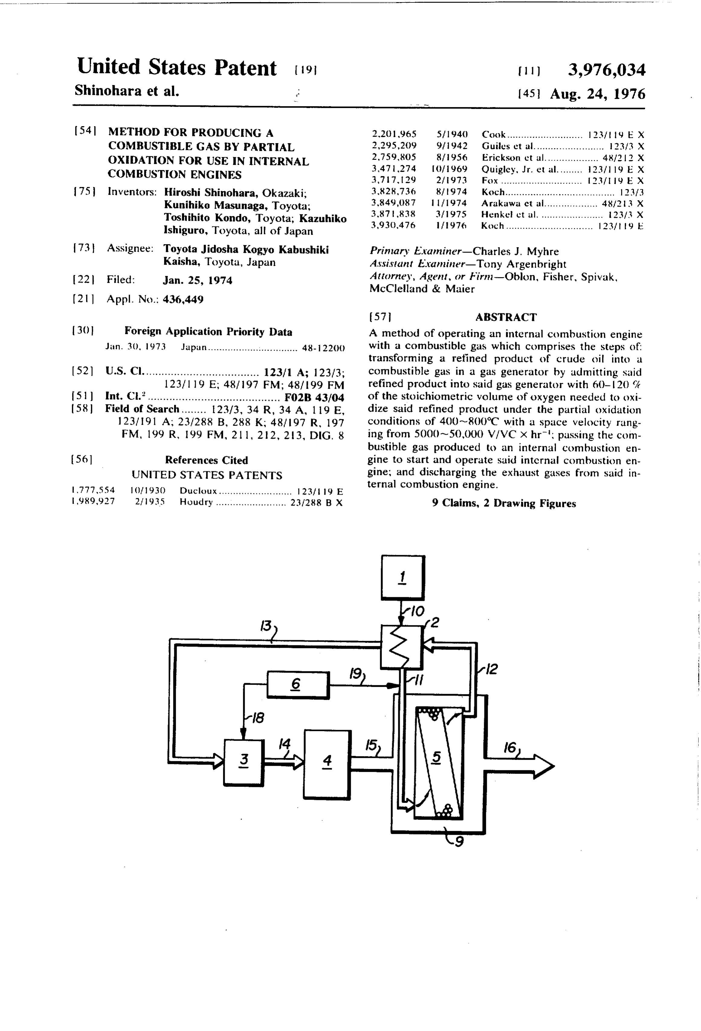
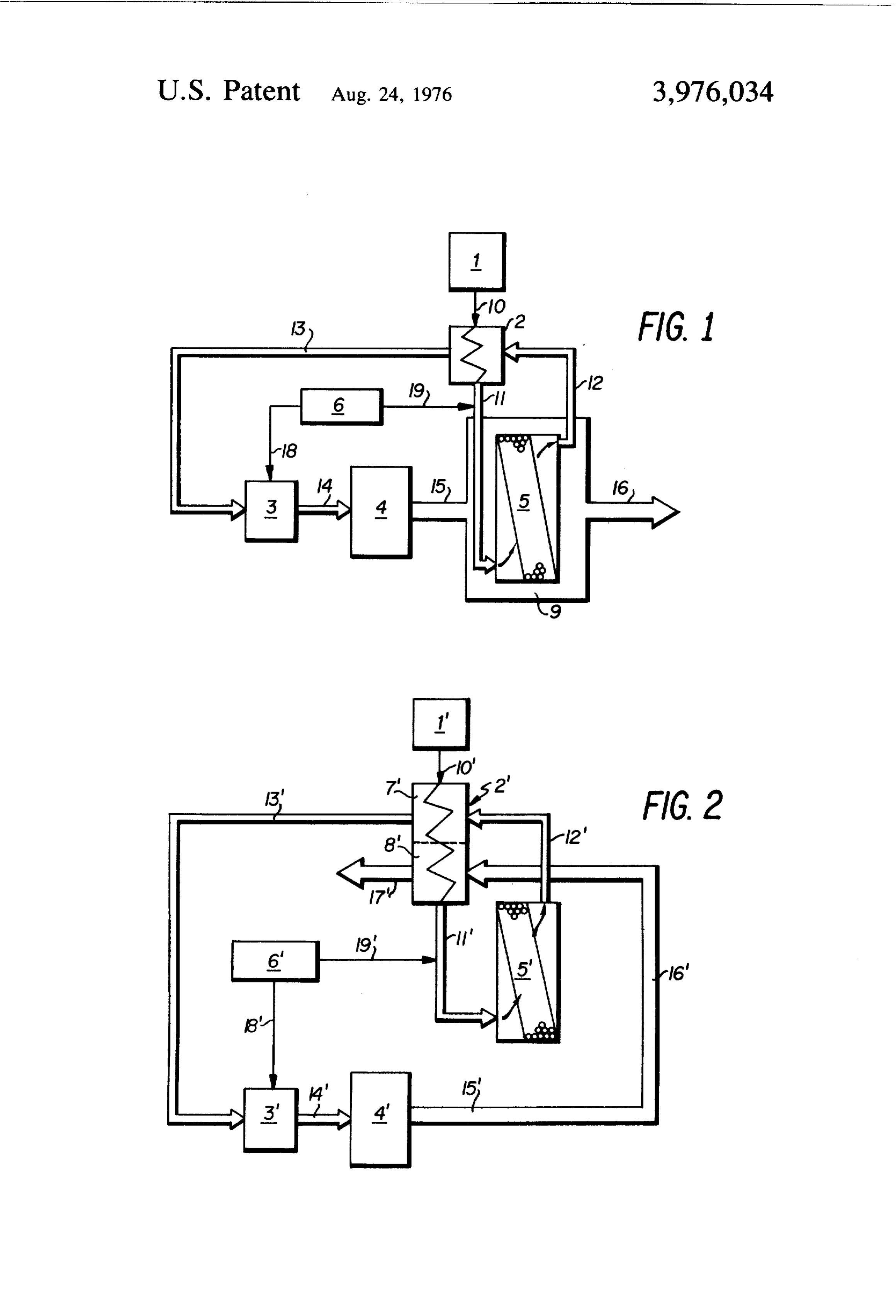
2. Description of the Prior Art Usually, when natural gas or LPG are used in auto Recently, air pollution caused by the exhaust gas 5 mobile engines, poor suction efficiency results with a emissions from internal combustion engines, particu resultant decrease in output. The feature of the present larly gasoline engines has become a serious public con invention is that even non-reacting materials. Such as cern. In order to solve this problem, various procedures liquid hydrocarbons, including gasoline and distillate have been developed and placed in practice such as the oil which cannot be transformed into combustible reduction of engine compression ratios, the burning of gases, are supplied to the engine, which prevents any fuel in the presence of excess amounts of air, the ad decrease in the engine's output. Also, no apparatus is justment of ignition timing and other engine controls, needed for disposal of the exhaust gas, and as illus and the use of special devices such as positive crank trated in the drawings, the internal combustion engines case ventilators, exhaust gas recirculators, catalytic can be started simply and economically. mufflers and exhaust manifold reactors. These meas 2 s In one embodiment of the invention as shown in FIG. ures, however, have not been able to satisfactorily solve 1, fuel is introduced from fuel tank 1 into fuel pipe 10, the exhaust gas emission problem. These techniques heated in the heat exchanger 2, and then passed also have the disadvantages of having complicated through pipe 1 1. The fuel, together with the air intro structures, they use expensive, precious metals such as duced into the duct 19 through the air cleaner 6, goes palladium or platinum, or they have limited durability. 30 into the heat exchanger 9 which contains built-in gas Other procedures for solving the pollution problem generator 5. The fuel is heated in the heat exchanger have focused on modifications of the fuels used. How and transformed into a combustible gas by partial oxi ever, the modifications that would be required for the dation in the gas generator 5. refineries would involve enormous costs. Even with The combustible gas then goes through the pipe 12, is these changes, however, there would still be no signifi 35 cooled by the heat exchanger 2 and then passes cant changes in the quality of gasoline marketed, through pipe 13 into the carburetor 3 which contains Recently, other fuels such as natural gas and LPG air which has come through duct 18 from the air have received attention as possible fuels for automobile cleaner 6. The mixture of the combustible gas and air, engines. The use of these fuels has met with a degree of supplied through the intake manifold 14, starts the success in reducing automobile emissions. However, 40 engine 4. The exhaust gases from the combustion in the use of natural gas or LPG in automobile engines engine 4 pass through exhaust manifold 15 into the requires pressure vessels for storage of the gases. In heat exchanger 9, in which is contained gas generator addition, the methods of supply of the gases involve 5, where the gases heat gas generator 5 and the pipe 1 1 hazards. Also, compressors for compressing the gases for the fuel-air mixture. The exhaust gas then passes as well as storage tanks are required. Thus the use of 45 from heat exchanger 9 and exits through the pipe 16. natural gas or LPG in automobile engines in an addi In a second embodiment of the invention as shown in tional heavy economic burden, although these fuels are FIG. 2, the fuel is introduced from the fuel tank 1' effective in mitigating the exhaust gas emissions in through the fuel pipe 10' into the heat exchanger 2' comparison to gasoline. consisting of an upper layer and a lower layer where the A need, therefore, continues to exist for a method of 50 fuel is heated. The fuel then passes into the pipe 11. satisfactorily reducing the pollutants in automobile The fuel, together with the air passed into the duct 19' emissions. through the air cleaner 6', flows into the gas generator SUMMARY OF THE INVENTION 5' where it is transformed into a combustible gas. The combustible gas flows through the pipe 12' into
Accordingly, one object of the present invention is to 55 the top layer 7" of the heat exchanger 2' where it is provide a method of reducing harmful exhaust gas cooled. The gas then flows through the pipe 13' into emissions from automobiles. the carburetor 3' into which air is taken via the duct Another object of the invention is to provide a com 8 from the air cleaner 6'.
bustible gas from refined products of crude oil. The mixture of the combustible gas and air, supplied Yet another object of the invention is to provide a 60 through the intake manifold 14" starts the engine 4". method of operating an internal combustion engine on The exhaust gas from the combustion process in the a combustible gas to reduce automobile exhaust gas engine 4, passes through the exhaust manifold 15' and emissions. the duct 16' into the bottom layer 8' of the double layer Briefly, these objects and other objects of the inven heat exchanger 2' where the fuel already heated in the tion as hereinafter will become more readily apparent 65 top layer 7" is again intensely heated. can be attained by a method of operating an internal Suitable fuels for the present invention include re combustion engine with a combustible gas, which com fined products of crude oil such as LPG, gasoline, dis prises the steps of transforming a refined product of tillate oil, kerosene and fuel oil; alcohols such as methyl
Page 4
alcohol, ethyl alcohol, propyl alcohol and butyl alco fore, the optimum temperature for these materials hol, aromatic hydrocarbons such as benzene, toluene, ranges from 400 to 800°C.
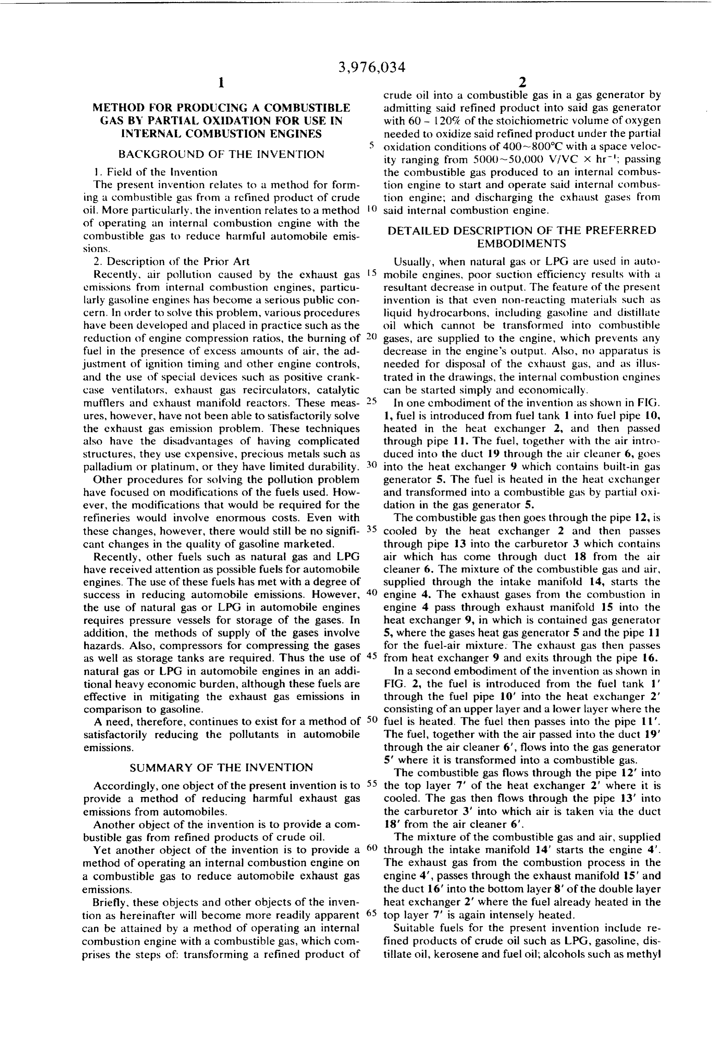
xylene, mesitylene and ethylbenzene, saturated hydro A catalyst for the partial oxidation of the fuel is not carbons such as ethane, propane, butane, pentane. always necessary for the gas generator of the present hexane, heptane, octane, cyclopentane and cyclohex invention. However, a more efficient generation of ane, and unsaturated hydrocarbons such as acetylene, combustible gas is possible in the presence of catalysts. ethylene, propylene, but ene, pentene, hexene and hep Suitable catalysts for the conversion reaction include tene. Among these fuels, the most preferred are gaso transition metals such as nickel, iron, cobalt, chro line, light oil, heating oil, benzene, toluene, hexane. mium, platinum, tungsten, rhodium, molybdenum, pill isooctane. hexene, cyclohexane. methyl alcohol and () ladiun, uranium, rhenium and oxides of these ele ethyl alcohol. ments. Suitable reaction promoters include the oxides, The partial oxidation of the fuel may be expressed as carbonates and nitrates of alkali metals such as lithium, a partial oxidation reaction or CO generating reaction sodium, potassium and cesium and alkaline earth met as shown by equation (i). Equations (ii) and (iii) repre als such as beryllium, magnesium, calcium, barium and sent secondary reactions which also have been ob 5 strontium.
served. Suitable carriers for supporting the catalysts include alumina, silica, magnesia, dolomite, zeolite, cement
CH + 2 () - , (O + 1 . . i. and brick (procelain or pottery).
(c) + H. - CH H.() ii. In the tests of the combustion system, it has been
found that the best results can be obtained when the
The volume of oxygen added to the fuel in the partial catalyst is nickel oxide supported on alumina or silica, oxidation reaction can be determined from equation and the reaction promoter is an oxide of calcium, mag nesium or vanadium.
(iv) and consequently the volume of air can be calcu The use of inorganic heat-resistant substances such lated from the volume of oxygen added. as glass wool or stainless steel balls as a filler material
for the gas generator is also very effective. A further wherein useful improvement is the installation of a partition, X = volume of oxygen added (g/l mole of fuel); wall or baffle wall made of chamotte brick, agalmato Y - stoichiometric volume of oxygen needed to pur lite brick, magnesium brick, chrome brick or carborun tially oxidize the fuel (g/l mole of fuel). dum brick in the gas generator.
The ratio of oxygen added in the industrial genera It is unclesirable that the volume of oxygen supplied tion of combustible gases from the fuel is usually about to the gas generator be less than 60% of its stoichiomet 100 - 150%, and therefore, a catalyst is used. In the ric volume because volumes less than that increase the present invention, the available range of the oxygen 35 amount of carbon generated, decrease the amount of added is 5 - 50%. At oxygen ratios less than 20%, gas gas generated, thus decreasing the calorific value of the carbon is likely to precipitate on the walls of the tube of ture which consequently lowers the reaction tempera and slows down the rate of reaction. If, however, the gas generator with a resultant decrease in the vol the stoichiometric volume of the oxygen exceeds ume of gas produced. If the oxygen ratio exceeds 120%, the content of the non-combustible CO, and N, 130%, the quantities of carbon dioxide or unreacted components in the generated gas increase and quanti oxygen may increase. However, no great increases in ties of unreacted oxygen are present in the gas which is the volume of combustible gas can be achieved. very dangerous. Also, the presence of oxygen in the In both of the operable embodiments of the inven combustible gas increases the calorific value of the gas tion, the most favorable exhaust gas conditions were while it accelerates the deterioration of the catalyst. obtained when the ratio of oxygen was 60 - 20%. 45
In the operation of the system, the fuel in the heat Thus, the stoichiometric volume of the gas should be exchanger is usually heated to 200-1200°C. If the limited If the to the range of 60 to 120%.
reaction temperature is less than 400°C the rate temperature is below 200°C, the partial oxidation of of reaction decreases which results in a decrease in the the fuel is slow which results in only a relatively small amount of gas generated, the reactivity is lower, which amount of gas generation.
If the temperature is over 1200°C, the content of drocarbons, and carbonin begins results in an increase the amount of unreacted hy to precipitate, which is carbon dioxide in the gas increases, the thermal decom not desirable. If the reaction temperature is allowed to position intensifies, and the precipitation of carbon exceed 800°C, the hydrocarbon fuel undergoes normal increases which results in a decrease in the gas energy density and of the output. At temperatures ranging 55 decomposition which results in an increase of the non combustible CO component in the generated gas and from 1 000 to 1200°C, the red-hot tube wall of the gas instability concerning the amount and composition of generator induces thermal decomposition of the hydro the generated gas. Also, the heat resistance of the cata carbons which results in reduced levels of generation of lyst becomes questionable. Thus, the optimum reaction the combustible gas and an uncertainty concerning the temperature ranges from 400 to 800°C. gas composition. At temperatures ranging from 200 to As for the space velocity of the gases within the gas 300°C, kerosene and fuel oil do not readily evaporate generator, velocities less than 500 VIVC X hr' are not and substantially reduced levels of conversion of the desirable, because at these velocities relatively large oils into a combustible gas results. Alcohols and lower amounts of catalyst are needed and accordingly the hydrocarbons, however, readily evaporate at these capacity of the reactor has to be larger. Velocities temperatures and are readily converted into a combus 65 greater than 50,000 VIVC X hr' are equally undesir tible gas, even at 200~300°C. Lower hydrocarbons able, because at these velocities the progress of the are useful as a fuel, but they are easily affected by the reaction is insufficient which results in an increased temperature of the partial oxidation conditions. There content of the unreacted hydrocarbons, a decrease in
Page 5
the amount of generated gas and an increase in the EXAMPLE amount of precipitated carbon. Also the durability of the catalyst is questionable. Thus, the optimum space A combustible gas was formed in an apparatus de velocity ranges from 5000 to 50,000 V/VC X hr (Vis scribed in the first embodiment of the invention and defined as the volume (liters) of gas material flowing then burned in an internal combustion engine 4. The over the catalyst per hour and VC is defined as the combustible gas was formed by admitting n-hexane and volume of catalyst in liters.). air into the gas generator which was maintained at a In the absence of a catalyst in the gas generator, temperature of 700°C. The temperature of the gas precipitation of carbon can be prevented by optimizing () mixture, i.e., n-hexane and oxygen added as air (50% the volume of added air. ' ' - oxygen ratio) in the entrance to the gas generator was After the combustible gas is generated in the gas 350°C. The gas mixture was partially oxidized over a generator, it is cooled in the heat exchanger and sent to catalyst in the generator and the composition of the the engine where, of course, ignition takes place. resulting gas was 36 vol% hydrogen, 40 vol% nitrogen, The composition of the combustible gas produced in 6 vol% methane, 17 vol% carbon monoxide, and l vol the gas generator which varies depending upon the 5 % carbon dioxide. The composition of the combustible partial oxidation conditions, is generally as follows in gas in the absence of a catalyst was l l vol% hydrogen, the absence of a catalyst: hydrogen 10~40%, carbon 46 vol% nitrogen, 15 vol% methane, 16 vol% carbon monoxide 30-~75%, methane 20-60%, dry gases other vol%. monoxide, 9 vol% dry gases other than methane and 3 than methane (C. C. gas distillate) 5~20%, and car 20 carbon dioxide.
bon dioxide 0-5%. If a catalyst is present in the gas EXAMPLE 2 generator for the partial oxidation conversion, the composition of the combustible gas is generally as foll When the system described in the second enabodi lows: hydrogen 50~70%, carbon monoxide 20-30%, scribedwasment operated under the same conditions de in Example 1, no great difference was found in methane 5 - 5%, dry gases other than methane (C, C the compositions of the combustible gas and the gener gas distillate) trace, and carbon dioxide O-2%.
The water content of the generated gas in the ab ated ple gas obtained in comparison to the system of Exam
sence of catalyst or in the presence of a partial oxida In the first and second cnbodiments of the invention, tion catalyst is in the range of O to 2 volume 7. full transformation of fuel into combustible gases in The combustible gas cooled in the heat exchanger is 30 internal combustion engine systems is illustrated. In an mixed in the carburetor with an adduate amount of air. alternative situation a mixture of combustible gases In ordinary gasoline engines the airffuel ratio ranges containing partially unreacted hydrocarbons, instead of from 7 - 16:1, but the stoichiometric air/fuel ratio, though variable depending upon the fuel composition is aingas order consisting of a fully transformed fuel can be used to improve the power output of an engine by
The range of airffuel ratios useful in the present in chamber ofthetheefficiency increasing engine.
of suction into the combustion vention is from 0.2~8: 1. However, the lower ratios are Having now fully described the invention, it will be effective for anti-pollution purposes, the optimum apparent to one of ordinary skill in the art that many ranging from 1 to 6. changes and modifications can be made thereto with The combustible gas of the present invention has a 40 out departing from the spirit or scope of the invention high spontaneous ignition point and a wide explosive as set forth herein.
range. Therefore, it can be used both as a lean mixture What is claimed as new and intended to be covered and as a rich mixture. These properties of the combus by Letters Patent is:
tible gas of the present invention is found useful. 1. A method of operating an internal combustion The vaporous mixture with the air/fuel ratio indi 45 engine with a combustible gas, which comprises the cated above burns in the combustion chamber of the steps of transforming a refined product of crude oil engine thereby, of course, developing engine power into a combustible gas characterized by a composition and emitting burned exhaust gas. The composition of comprising 10% - 70% hydrogen, 20% - 75% carbon the harmful elements in the burned exhaust gas can be monoxide, 5 - 60% methane, 0 - 5% carbon dioxide, reduced by the procedure of the present invention to 50 and up to 20% dry hydrocarbon gases in a generator by the same levels achieved when the engine is run under admitting said refined product into said gas generator the steam cracking conditions disclosed in SAE Paper with 60 - 120% of the stoichiometric volume of oxygen No. 68.0769 by R. C. Lee and D. B. Wimmer (published needed to oxidize said refined product under the partial 1968 by SAE) wherein n-hexane was burned at 1,000 oxidation conditions of 400-800°C with a space ve F (540°C) at 3.4 atms pressure with a steam/hexane locity ranging from 5000 ~ 50,000 V/VC X hr'; pass weight ratio of 1.71 Lb/Lb. Under these operating ing the combustible gas produced to an internal com conditions a clean exhaust was produced of 2.52g/mile bustion engine to start and operate said internal com of NO, 0.86 g/mile of hydrocarbons and 1.59 g/mile of bustion engine; and discharging the exhaust gases from CO. R. C. Lee and others have called this exhaust gas said internal combustion engine. composition a “clean-exhaust'. In the present inven 60 2. The method of claim 1, wherein said refined prod tion, the clean exhaust passes through the exhaust man uct is oxidized with said oxygen in said gas generator in ifold where it subsequently preheats the gas generator the presence of a catalyst.
or the gas mixture, and then exits the system. 3. The method of claim 1, wherein said exhaust gases Having generally described this invention, a further are sent to Said gas generator to heat said gas generator understanding can be obtained by reference to certain before said exhaust gases are discharged. specific examples which are provided herein for pur 4. The method of claim 1, wherein said exhaust gases poses of illustration only and are not intended to be are sent to a heat exchanger to heat said heat ex limiting unless otherwise specified. changer before said exhaust gases are discharged.
Page 6
5. The method of claim 1, which further comprises: gases from said operating engine into the lower layer of cooling said combustible gas in a heat exchanger; pass said heat exchanger, whereby the combustible gas pre ing said cooled combustible gas to a carburetor, passing sent in the upper layer of said heat exchanger is more said cooled combustible gas from said carburetor into intensely heated; and discharging the exhaust gas from said internal combustion engine together with air from the heat exchanger into the atmosphere. an air cleaner to start the engine; discharging the ex 7. The method of claim 2, wherein said catalyst is haust gas from the engine to a heat exchanger which nickel, iron, cobalt, chromium, platinum, tungsten, contains a gas generator; heating an air and fuel mix rhodium, molybdenum, palladium, uranium, rhenium ture within said gas generator with said discharged exhaust gas, and discharging said exhaust gas into the () or oxides thereof.
atmosphere. 8. The method of claim 2, wherein said catalyst is 6. The method of claim 1, which further comprises: combined with a reaction promoter selected from the cooling said gas in the upper layer of a heat exchanger group consisting of the oxides, carbonates and nitrates which contains an upper and lower layer; passing said of sodium, lithium, cesium, potassium, magnesium, cooled combustible gas into a carburetor; passing the 5 beryllium, calcium, strontium and barium. combustible gas from said carburetor into said internal 9. The method of claim 2, wherein said catalyst is combustion engine together with the air from an air supported on a silica, alumina, magnesia, dolomite, cleaner, starting and operating said engine with said zeolite, cement or brick carrier. combustible gas and air; passing the evolved exhaust sk 2; x xk k
Provenance
- Collection
- Cited prior art
- Original PDF
- patentimages.storage.googleapis.com →
- Filed
- 1974-01-25
- Pages
- 6
- Method
- pdftotext (the PDF's own text layer) + pdftoppm 300dpi page scans
- Source
- Google Patents bibliographic record
- Granted
- 1976-08-24
- Inventors
- Hiroshi Shinohara; Kunihiko Masunaga; Toshihito Kondo; Kazuhiko Ishiguro; Toyota Jidosha Kogyo KK
- Transcribed from
- patentimages.storage.googleapis.com →