patent · US4086878
Combustion process for externally controlled reciprocating piston internal combustion engine operating with hydrogen injection
2 May 1978
Page 1 — bibliographic record
United States Patent (19)
Eisele et al.
(54) COMBUSTON PROCESS FOR 2,205,493 6/1940 Saurer ................................ 123/30 C EXTERNALLY CONTROLLED 2,470,747 5/1949 Shepherd ... ... 123/27 GE X RECIPROCATING PSTON INTERNAL 2,921,566 1/1960 Meurer............................... 123/30 C COMBUSTION ENGINE OPERATING WITH 2,982,270 5/1961 Seegelken .......................... 123/30 C HYDROGENNECTION 3,425,399 2/1969 Ward et al. ................ 123/27 GE X
FOREIGN PATENT DOCUMENTS
75 Inventors: Erwin Eisele, Stuttgart; Klaus Binder,
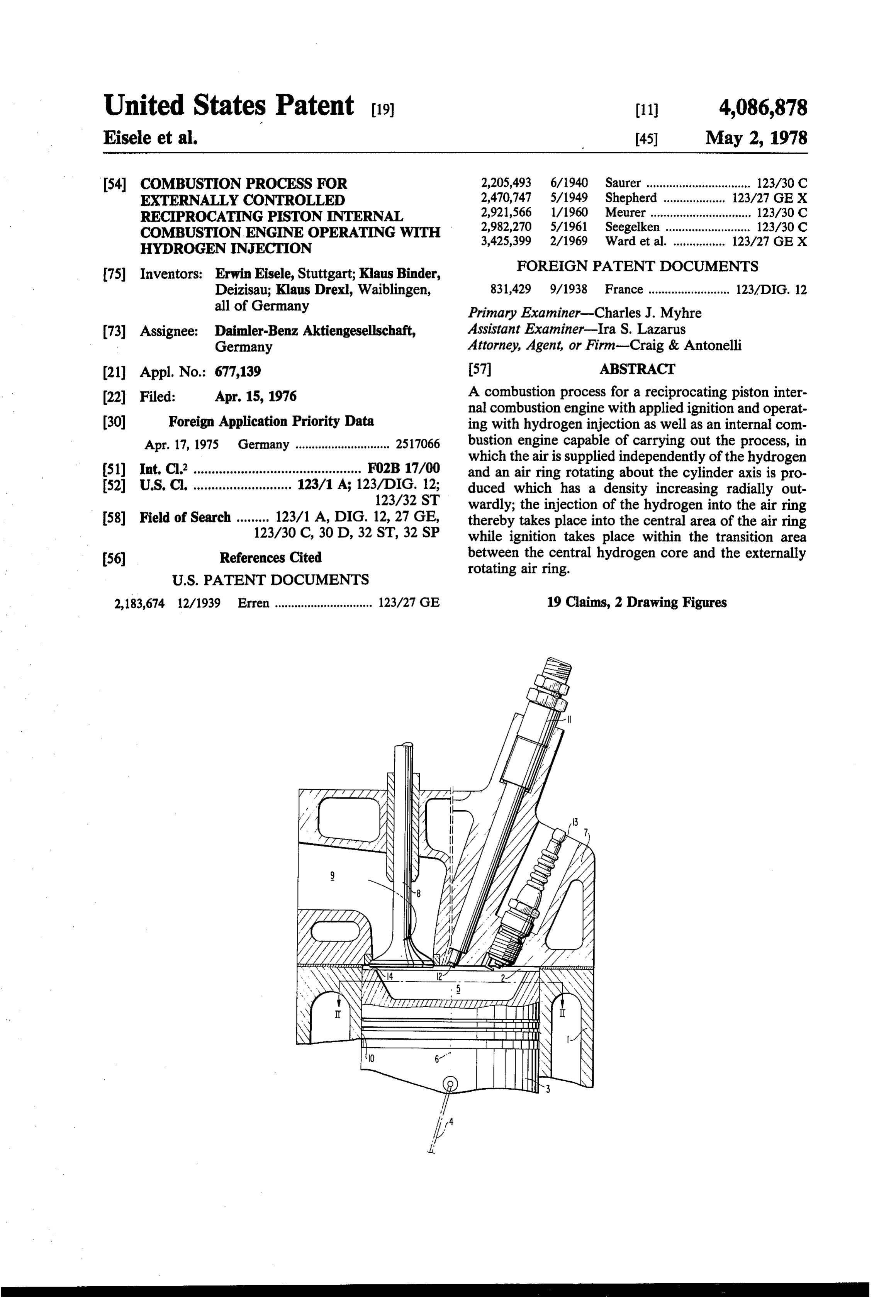
Deizisau; Klaus Drexl, Waiblingen, 831,429 9/1938 France ......................... 123/DIG. 12 all of Germany Primary Examiner-Charles J. Myhre (73) Assignee: Daimler-Benz Aktiengesellschaft, Assistant Examiner-Ira S. Lazarus Germany Attorney, Agent, or Firm-Craig & Antonelli (21) Appl. No.: 677,139 57 ABSTRACT 22 Filed: Apr. 15, 1976 A combustion process for a reciprocating piston inter nal combustion engine with applied ignition and operat (30) Foreign Application Priority Data ing with hydrogen injection as well as an internal com Apr. 17, 1975 Germany ............................. 2517066 bustion engine capable of carrying out the process, in which the air is supplied independently of the hydrogen (51) Int, Cl” .............................................. FO2B 17/00 and an air ring rotating about the cylinder axis is pro (52) U.S. C. ........................... 123/1 A; 123/DIG. 12; duced which has a density increasing radially out 123/32 ST wardly; the injection of the hydrogen into the air ring 58) Field of Search ......... 123/1 A, DIG. 12, 27 GE, thereby takes place into the central area of the air ring 123/30 C, 30 D, 32 ST, 32 SP while ignition takes place within the transition area (56) References Cited between the central hydrogen core and the externally rotating air ring.
2,183,674 12/1939 Erren .............................. 123/27 GE 19 Claims, 2 Drawing Figures
/ 3
Page 2
Drawing sheet — no readable text.
Page 3
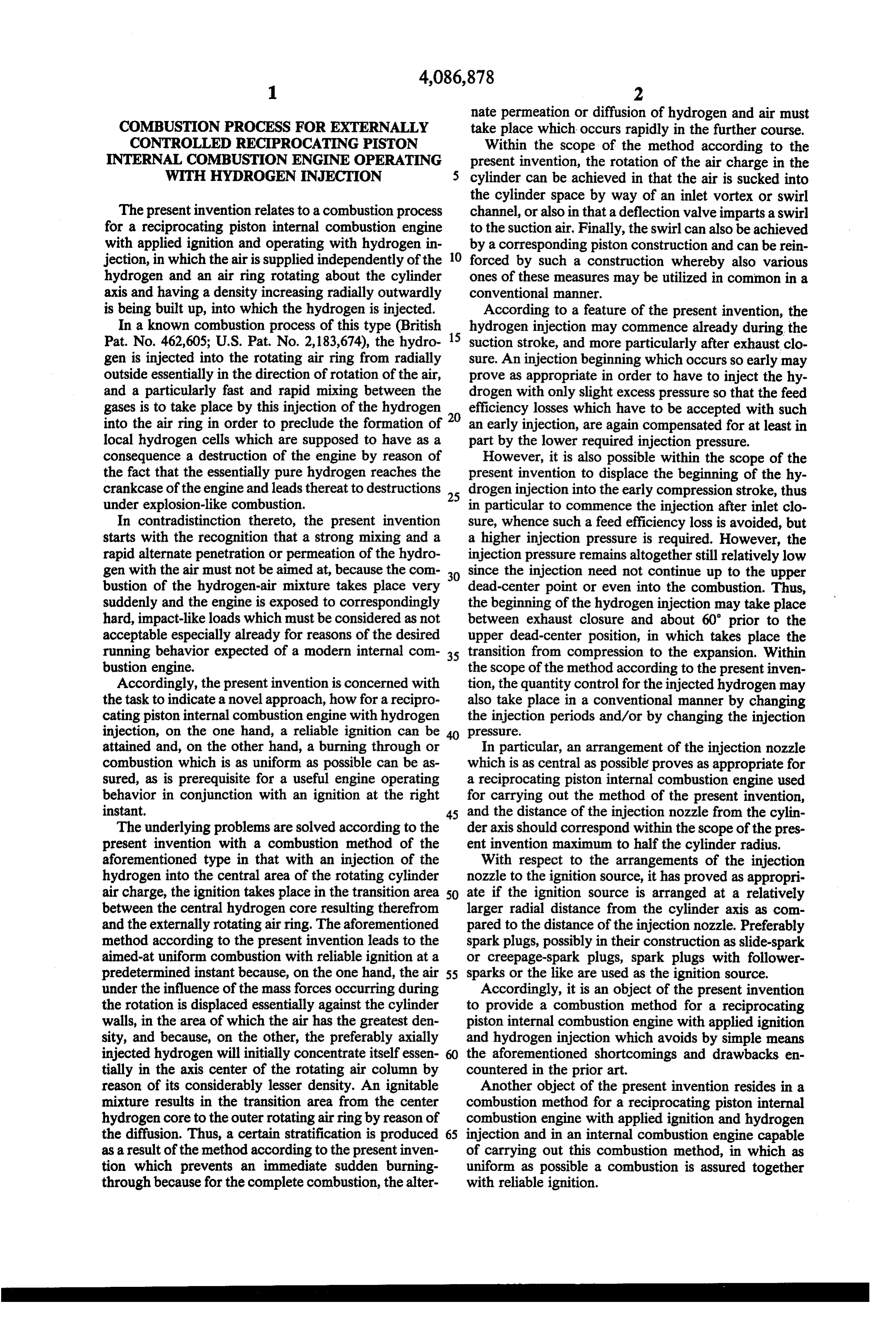
nate permeation or diffusion of hydrogen and air must
COMBUSTION PROCESS FOR EXTERNALLY take place which occurs rapidly in the further course. CONTROLLED REC PROCATING PSTON Within the scope of the method according to the INTERNAL COMBUSTON ENGINE OPERATING present invention, the rotation of the air charge in the WITH HYDROGEN INJECTION cylinder can be achieved in that the air is sucked into the cylinder space by way of an inlet vortex or swirl
The present invention relates to a combustion process channel, or also in that a deflection valve imparts a swirl for a reciprocating piston internal combustion engine to the suction air. Finally, the swirl can also be achieved with applied ignition and operating with hydrogen in by a corresponding piston construction and can be rein jection, in which the air is supplied independently of the 10 forced by such a construction whereby also various hydrogen and an air ring rotating about the cylinder ones of these measures may be utilized in common in a axis and having a density increasing radially outwardly conventional manner.
is being built up, into which the hydrogen is injected. According to a feature of the present invention, the In a known combustion process of this type (British 15 hydrogen injection may commence already during the Pat. No. 462,605; U.S. Pat. No. 2,183,674), the hydro suction stroke, and more particularly after exhaust clo gen is injected into the rotating air ring from radially sure. An injection beginning which occurs so early may outside essentially in the direction of rotation of the air, prove as appropriate in order to have to inject the hy and a particularly fast and rapid mixing between the drogen with only slight excess pressure so that the feed gases is to take place by this injection of the hydrogen 20 efficiency losses which have to be accepted with such into the air ring in order to preclude the formation of an early injection, are again compensated for at least in local hydrogen cells which are supposed to have as a part by the lower required injection pressure. consequence a destruction of the engine by reason of However, it is also possible within the scope of the the fact that the essentially pure hydrogen reaches the present invention to displace the beginning of the hy crankcase of the engine and leads thereat to destructions 25 drogen injection into the early compression stroke, thus under explosion-like combustion. in particular to commence the injection after inlet clo In contradistinction thereto, the present invention sure, whence such a feed efficiency loss is avoided, but starts with the recognition that a strong mixing and a a higher injection pressure is required. However, the rapid alternate penetration or permeation of the hydro injection pressure remains altogether still relatively low gen with the air must not be aimed at, because the com since the injection need not continue up to the upper bustion of the hydrogen-air mixture takes place very 30 dead-center point or even into the combustion. Thus, suddenly and the engine is exposed to correspondingly the beginning of the hydrogen injection may take place hard, impact-like loads which must be considered as not between exhaust closure and about 60 prior to the acceptable especially already for reasons of the desired upper dead-center position, in which takes place the running behavior expected of a modern internal com 35 transition from compression to the expansion. Within bustion engine. the scope of the method according to the present inven Accordingly, the present invention is concerned with tion, the quantity control for the injected hydrogen may the task to indicate a novel approach, how for a recipro also take place in a conventional manner by changing cating piston internal combustion engine with hydrogen the injection periods and/or by changing the injection injection, on the one hand, a reliable ignition can be pressure.
attained and, on the other hand, a burning through or In particular, an arrangement of the injection nozzle combustion which is as uniform as possible can be as which is as central as possible proves as appropriate for sured, as is prerequisite for a useful engine operating a reciprocating piston internal combustion engine used behavior in conjunction with an ignition at the right for carrying out the method of the present invention, instant. 45 and the distance of the injection nozzle from the cylin The underlying problems are solved according to the der axis should correspond within the scope of the pres present invention with a combustion method of the ent invention maximum to half the cylinder radius. aforementioned type in that with an injection of the With respect to the arrangements of the injection hydrogen into the central area of the rotating cylinder nozzle to the ignition source, it has proved as appropri air charge, the ignition takes place in the transition area 50 ate if the ignition source is arranged at a relatively between the central hydrogen core resulting therefrom larger radial distance from the cylinder axis as com and the externally rotating air ring. The aforementioned pared to the distance of the injection nozzle. Preferably method according to the present invention leads to the spark plugs, possibly in their construction as slide-spark aimed-at uniform combustion with reliable ignition at a or creepage-spark plugs, spark plugs with follower predetermined instant because, on the one hand, the air 55 sparks or the like are used as the ignition source. under the influence of the mass forces occurring during Accordingly, it is an object of the present invention the rotation is displaced essentially against the cylinder to provide a combustion method for a reciprocating walls, in the area of which the air has the greatest den piston internal combustion engine with applied ignition sity, and because, on the other, the preferably axially and hydrogen injection which avoids by simple means injected hydrogen will initially concentrate itself essen the aforementioned shortcomings and drawbacks en tially in the axis center of the rotating air column by countered in the prior art.
reason of its considerably lesser density. An ignitable Another object of the present invention resides in a mixture results in the transition area from the center combustion method for a reciprocating piston internal hydrogen core to the outer rotating air ring by reason of combustion engine with applied ignition and hydrogen the diffusion. Thus, a certain stratification is produced 65 injection and in an internal combustion engine capable as a result of the method according to the present inven of carrying out this combustion method, in which as tion which prevents an immediate sudden burning uniform as possible a combustion is assured together through because for the complete combustion, the alter with reliable ignition.
Page 4
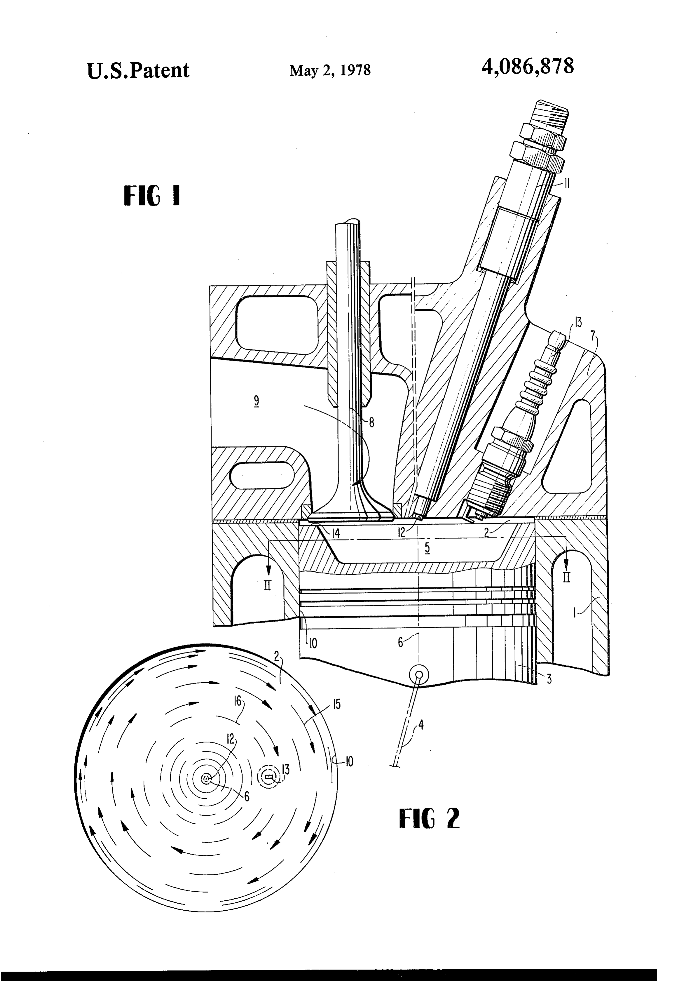
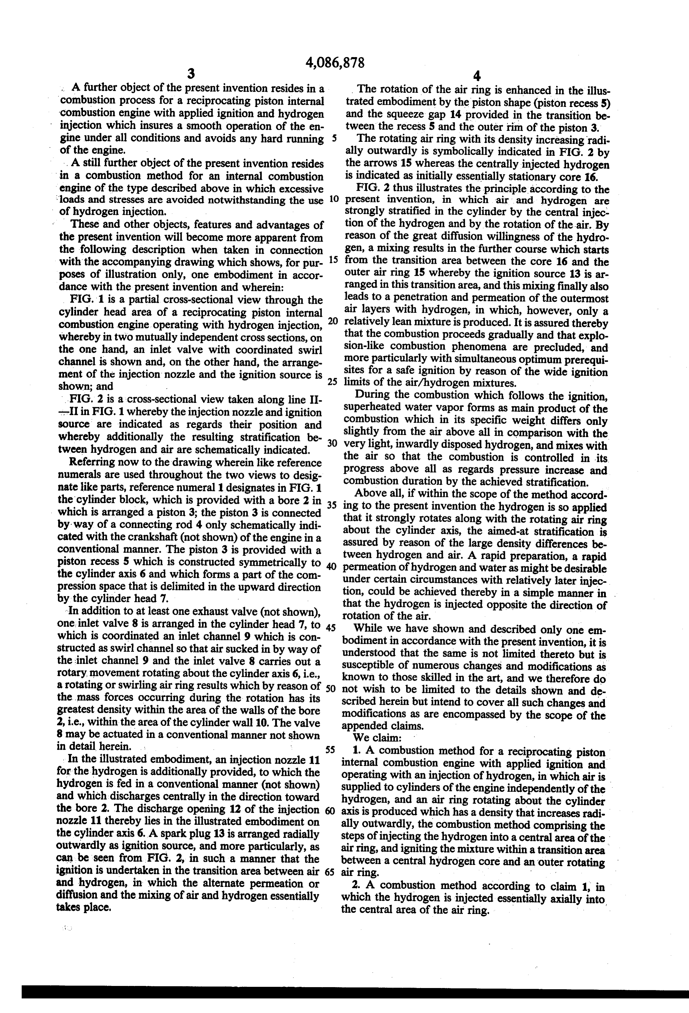
A further object of the present invention resides in a The rotation of the air ring is enhanced in the illus combustion process for a reciprocating piston internal trated embodiment by the piston shape (piston recess 5) combustion engine with applied ignition and hydrogen and the squeeze gap 14 provided in the transition be injection which insures a smooth operation of the en tween the recess 5 and the outer rim of the piston 3. gine under all conditions and avoids any hard running The rotating air ring with its density increasing radi of the engine, ally outwardly is symbolically indicated in FIG. 2 by . . A still further object of the present invention resides the arrows 15 whereas the centrally injected hydrogen in a combustion method for an internal combustion is indicated as initially essentially stationary core 16. engine of the type described above in which excessive FIG. 2 thus illustrates the principle according to the Sloads and stresses are avoided notwithstanding the use 10 present invention, in which air and hydrogen are of hydrogen injection. strongly stratified in the cylinder by the central injec These and other objects, features and advantages of tion of the hydrogen and by the rotation of the air. By the present invention will become more apparent from reason of the great diffusion willingness of the hydro the following description when taken in connection 15 gen, a mixing results in the further course which starts with the accompanying drawing which shows, for pur from the transition area between the core 16 and the poses of illustration only, one embodiment in accor outer air ring 15 whereby the ignition source 13 is ar dance with the present invention and wherein: ranged in this transition area, and this mixing finally also FIG. 1 is a partial cross-sectional view through the leads to a penetration and permeation of the outermost cylinder head area of a reciprocating piston internal air layers with hydrogen, in which, however, only a combustion engine operating with hydrogen injection, 20 relatively lean mixture is produced. It is assured thereby whereby in two mutually independent cross sections, on that the combustion proceeds gradually and that explo the one hand, an inlet valve with coordinated swirl sion-like combustion phenomena are precluded, and channel is shown and, on the other hand, the arrange more particularly with simultaneous optimum prerequi ment of the injection nozzle and the ignition source is 25 sites for a safe ignition by reason of the wide ignition limits of the air/hydrogen mixtures.
shown; and
During the combustion which follows the ignition,
FIG. 2 is a cross-sectional view taken along line II superheated --II in FIG. 1 whereby the injection nozzle and ignition water vapor forms as main product of the source are indicated as regards their position and slightly combustion which in its specific weight differs only whereby additionally the resulting stratification be very light, from the air above all in comparison with the tween hydrogen and air are schematically indicated. 30 the inwardly disposed hydrogen, and mixes with Referring now to the drawing wherein like reference air so that the combustion is controlled in its numerals are used throughout the two views to desig progress above all as regards pressure increase and nate like parts, reference numeral 1 designates in FIG. 1 combustion
Above duration by the achieved stratification.
all, if within the scope of the method accord the cylinder block, which is provided with a bore 2 in 35 ing to the present invention the hydrogen is so applied which is arranged a piston 3; the piston 3 is connected that it strongly rotates along with the rotating air ring by way of a connecting rod 4 only schematically indi about cated with the crankshaft (not shown) of the engine in a assured by reason of the the the cylinder axis, aimed-at stratification is large density differences be conventional manner. The piston 3 is provided with a tween hydrogen and air. A rapid piston recess 5 which is constructed symmetrically to permeation of hydrogen and water aspreparation, might be a rapid desirable the cylinder axis 6 and which forms a part of the com under certain circumstances with relatively later injec pression space that is delimited in the upward direction tion, could be achieved thereby in a simple manner in . by the cylinder head 7.
In addition to at least one exhaust valve (not shown), rotation hydrogen that the of the air.
is injected opposite the direction of one inlet valve 8 is arranged in the cylinder head 7, to 45 While we have shown and described only one em which is coordinated an inlet channel 9 which is con structed as swirl channel so that air sucked in by way of bodiment understood in accordance with the present invention, it is that the same is not limited thereto but is the inlet channel 9 and the inlet valve 8 carries out a rotary movement rotating about the cylinder axis 6, i.e., known to thosenumerous susceptible of changes and modifications as a rotating or swirling air ring results which by reason of 50 not wish to be limited tothetheart,details skilled in and we therefore do shown and de the mass forces occurring during the rotation has its scribed herein but intend to cover all such changes and greatest density within the area of the walls of the bore modifications as are encompassed by the scope of the 2, i.e., within the area of the cylinder wall 10. The valve appended claims.
8 may be actuated in a conventional manner not shown We claim:
in detail herein. 55 1. A combustion method for a reciprocating piston . In the illustrated embodiment, an injection nozzle 11 internal combustion engine with applied ignition and for the hydrogen is additionally provided, to which the operating with an injection of hydrogen, in which air is hydrogen is fed in a conventional manner (not shown) supplied to cylinders of the engine independently of the and which discharges centrally in the direction toward hydrogen, and an air ring rotating about the cylinder the bore 2. The discharge opening 12 of the injection axis is produced which has a density that increases radi nozzle 11 thereby lies in the illustrated embodiment on ally the cylinder axis 6. A sparkplug 13 is arranged radially stepsoutwardly, the combustion method comprising the of injecting the hydrogen into a central area of the outwardly as ignition source, and more particularly, as air ring, and igniting the mixture within a transition area can be seen from FIG. 2, in such a manner that the between a central hydrogen core and an outer rotating ignition is undertaken in the transition area between air 65 air ring.
and hydrogen, in which the alternate permeation or 2. A combustion method according to claim 1, in diffusion and the mixing of air and hydrogen essentially which the hydrogen is injected essentially axially into takes place, the central area of the air ring.
Page 5
3. A combustion method according to claim 1, in from the longitudinal axis of the cylinder corresponding which the step of injecting includes beginning the hy at least essentially to the distance of the injection nozzle. drogen injection between an exhaust closure and about 12. An internal combustion engine according to claim 60 prior to an upper dead-center position, in which 11, characterized in that the injection nozzle is located takes place the transition from a compression to an 5 within a center area of a cylinder and the ignition expansion. source is located at a radial distance from the injection 4. A combustion method according to claim 3, char nozzle which amounts to between one-third to two acterized in that the step of injecting includes beginning thirds the radial length.
the hydrogen injection in a suction stroke of the engine. 10 13. An internal combustion engine according to claim 5. A combustion method according to claim 3, char 11, characterized in that the injection means is operable acterized in that the step of injecting includes beginning to begin an injection of the hydrogen between exhaust the hydrogen injection after an inlet closing. closure and about 60' of the upper dead-center position, 6. A combustion method according to claim 3, char in which takes place a transition from a compression to acterized in that the step of injecting includes beginning 15 an 14.
expansion.
An internal combustion engine according to claim the hydrogen injection early in a compression stroke of the engine. 11, characterized in that the injection means is operable 7. A combustion method according to claim 3, in to commence the injection of the hydrogen during a which the hydrogen is injected essentially axially into suction stroke of the engine. 15. An internal combustion engine according to claim the central area of the air-ring. 11, characterized in that the injection means is operable 8. A reciprocating piston internal combustion engine to with applied ignition and operating with a hydrogen inletcommence closure.
the injection of the hydrogen after an injection, means for supplying air to cylinders of the engine, independently of the hydrogen, in the form of 11,16.characterized
An internal combustion engine according to claim an air ring rotating essentially about a longitudinal axis 25 to commence theininjection that the injection means is operable of the hyrogen early in a of symmetry of respective cylinders, the air ring has a density that increases radially outwardly, characterized compression stroke.
by injection means for injecting the hydrogen into a 12, characterized combustion 17. An internal in that the engine according to claim injection means is arranged central area of the air ring so as to form a central hydro in the engine so as to inject the hydrogen essentially gen core in the rotating air ring, and externally con 30 axially into the central area of the air ring. trolled ignition means for igniting a hydrogen-air mix 18. A combustion method for a reciprocating piston ture within a transition area between the central hydro internal combustion engine operating with a hydrogen gen core and an outer rotating air ring. injection, means for supplying air to cylinders of the 9. An internal combustion engine according to claim engine in the form of an air ring rotating about a longi 8, characterized in that the injection means is arranged 35 tudinal axis of symmetry of the respective cylinders, the in the engine so as to inject the hydrogen essentially rotating air having a density that increases radially out axially into the central area of the air ring, wardly, the method comprising the steps of: 10. An internal combustion engine according to claim injecting the hydrogen into a central area of the air 8, with a cylinder head in which the injection means ring so as to form a central hydrogen core in the includes an injection nozzle which is arranged in an area 40 rotating air ring, and of the cylinder head near the longitudinal axis of sym igniting the mixture within a transition area between metry of the cylinder, characterized in that the injection the central hydrogen core and an outer rotating air nozzle is located at a distance from the longitudinal axis ring.
of symmetry of the cylinder corresponding at most to 19. A combustion method according to claim 18, about half the cylinder radius. 45 wherein the step of injecting the hydrogen includes 11. An internal combustion engine according to claim directing the hydrogen essentially axially into the cen 10, characterized in that the ignition means includes an tral area of the air ring.
ignition source which is arranged at a radial distance
Provenance
- Collection
- Cited prior art
- Original PDF
- patentimages.storage.googleapis.com →
- Filed
- 1976-04-15
- Pages
- 5
- Method
- pdftotext (the PDF's own text layer) + pdftoppm 300dpi page scans
- Source
- Google Patents bibliographic record
- Granted
- 1978-05-02
- Inventors
- Erwin Eisele; Klaus Binder; Klaus Drexl; Daimler Benz AG
- Transcribed from
- patentimages.storage.googleapis.com →