patent · US4722303
Method for operating an internal combustion engine
2 February 1988
Page 1 — bibliographic record
United States Patent (19) 11 Patent Number: 4,722,303 Leonhard 45 Date of Patent: Feb. 2, 1988 54 METHOD FOR OPERATING AN INTERNAL 4,476,818 10/1984 Yoon mor 123/3 COMBUSTON ENGINE 4,499,863 2/1985 Gandhi et al. ... 123/3
75 Inventor: Rolf Leonhard, Schwieberdingen,
Fed. Rep. of Germany OTHER PUBLICATIONS 73 Assignee: Robert Bosch GmbH, Stuttgart, Fed. SAE Technical Papers, Series 790 427 (Feb. 25-Mar. 2, Rep. of Germany 1979)-Methanol Decomposition Bottoming Cycle for
Primary Examiner-E. Rollins Cross 22 Filed: Jun. 10, 1986 Attorney, Agent, or Firm-Edwin E. Greigg 30 Foreign Application Priority Data 57 ABSTRACT Jul. 4, 1985 (DE Fed. Rep. of Germany ....... 3523855 A method is proposed for operating an internal combus 51) Int. Cl.' .............................................. FO2B 43/08 tion engine with decomposition gas generated by gas 52 U.S. Cl. ............................... 123/3; 123/DIG. 12; ifying methanol into hydrogen and carbon monoxide in 123/. A a gasification reactor. The enthalpy necessary for gas 58 Field of Search ................... 123/1 A, 3, DIG. 12 ifying the methanol is obtained from the heat of the (56) References Cited exhaust gas of the engine. To attain high efficiency and high power, the decomposition gas is injected at high
4,366,782 1/1983 Jackson et al. .................. ... 123/3 engine.
4,425,876 1/1984 Rutledge et al. ... 123/3 424,146 2/1984 Yoona. 123/3 21 Claims, 3 Drawing Figures
Page 2
Drawing sheet — no readable text.
Page 3
Drawing sheet — no readable text.
Page 4
Drawing sheet — no readable text.
Page 5
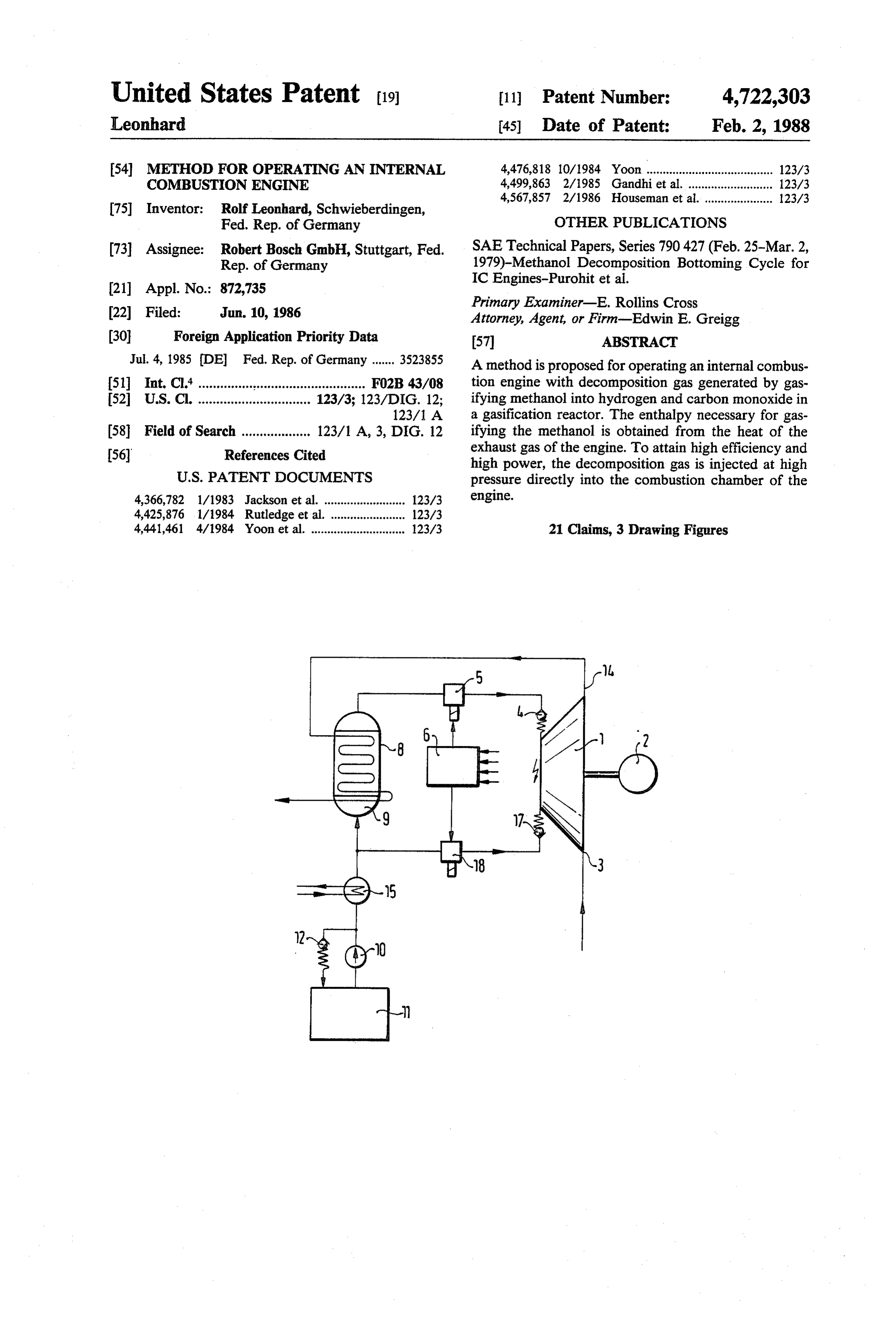
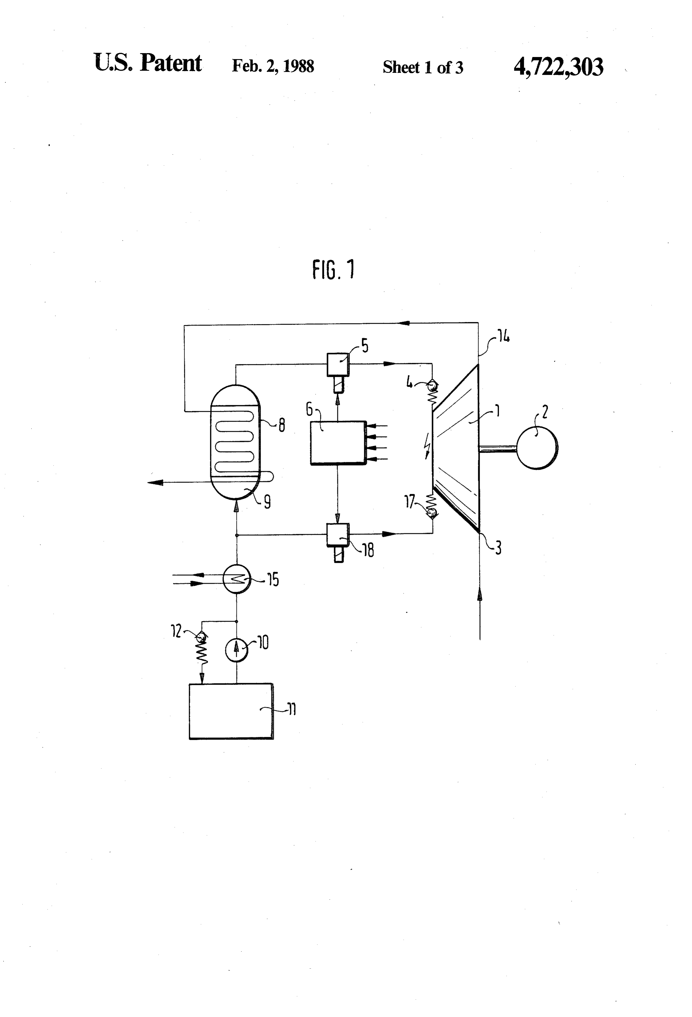
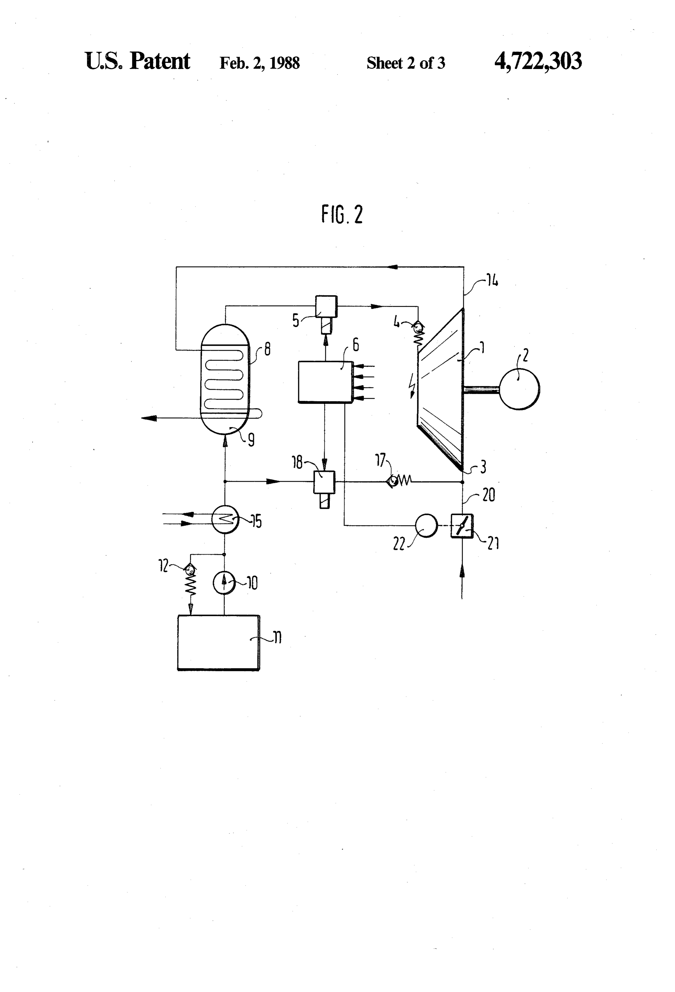
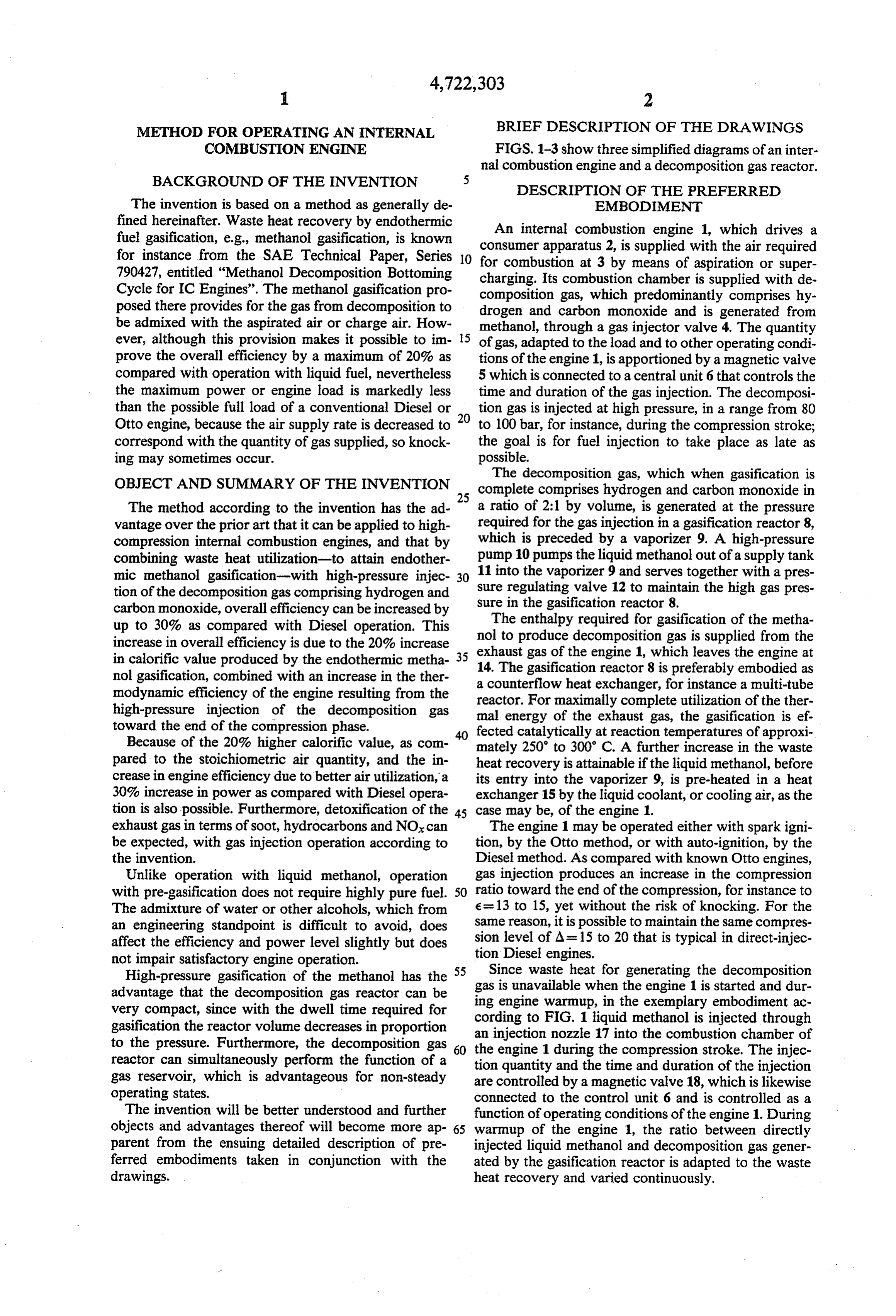
METHOD FOR OPERATING AN INTERNAL BRIEF DESCRIPTION OF THE DRAWINGS COMBUSTION ENGINE FIGS. 1-3 show three simplified diagrams of an inter nal combustion engine and a decomposition gas reactor.
DESCRIPTION OF THE PREFERRED
The invention is based on a method as generally de EMBODIMENT fined hereinafter. Waste heat recovery by endothermic An internal combustion engine 1, which drives a fuel gasification, e.g., methanol gasification, is known consumer apparatus 2, is supplied with the air required for instance from the SAE Technical Paper, Series 10 for combustion at 3 by means of aspiration or super 790427, entitled "Methanol Decomposition Bottoming
Cycle for IC Engines'. The methanol gasification pro charging. Its combustion chamber is supplied with de composition gas, which predominantly comprises hy posed there provides for the gas from decomposition to drogen and carbon monoxide and is generated from be admixed with the aspirated air or charge air. How methanol, through a gas injector valve 4. The quantity ever, although this provision makes it possible to im 15 of gas, adapted to the load and to other operating condi prove the overall efficiency by a maximum of 20% as tions of the engine 1, is apportioned by a magnetic valve compared with operation with liquid fuel, nevertheless 5 which is connected to a central unit 6 that controls the the maximum power or engine load is markedly less time and duration of the gas injection. The decomposi than the possible full load of a conventional Diesel or 20 tion gas is injected at high pressure, in a range from 80 Otto engine, because the air supply rate is decreased to to 100 bar, for instance, during the compression stroke; correspond with the quantity of gas supplied, so knock the goal is for fuel injection to take place as late as ing may sometimes occur. possible.
The decomposition gas, which when gasification is
OBJECT AND SUMMARY OF THE INVENTION
25 complete comprises hydrogen and carbon monoxide in
The method according to the invention has the ad a ratio of 2:1 by volume, is generated at the pressure vantage over the prior art that it can be applied to high required for the gas injection in a gasification reactor 8, compression internal combustion engines, and that by which is preceded by a vaporizer 9. A high-pressure combining waste heat utilization-to attain endother pump 10 pumps the liquid methanol out of a supply tank mic methanol gasification-with high-pressure injec 30 11 into the vaporizer 9 and serves together with a pres tion of the decomposition gas comprising hydrogen and sure regulating valve 12 to maintain the high gas pres carbon monoxide, overall efficiency can be increased by sure in the gasification reactor 8. up to 30% as compared with Diesel operation. This nolThe enthalpy required for gasification of the metha to produce decomposition gas is supplied from the increase in overall efficiency is due to the 20% increase exhaust in calorific value produced by the endothermic metha 35 14. The gas of the engine 1, which leaves the engine at gasification reactor 8 is preferably embodied as nol gasification, combined with an increase in the ther a counterflow heat exchanger, for instance a multi-tube modynamic efficiency of the engine resulting from the reactor. For maximally complete utilization of the ther high-pressure injection of the decomposition gas mal energy of the exhaust gas, the gasification is ef toward the end of the compression phase. fected catalytically at reaction temperatures of approxi Because of the 20% higher calorific value, as com mately 250 to 300° C. A further increase in the waste pared to the stoichiometric air quantity, and the in heat recovery is attainable if the liquid methanol, before crease in engine efficiency due to better air utilization, a its entry into the vaporizer 9, is pre-heated in a heat 30% increase in power as compared with Diesel opera exchanger 15 by the liquid coolant, or cooling air, as the tion is also possible. Furthermore, detoxification of the 45 case may be, of the engine 1. exhaust gas in terms of soot, hydrocarbons and NOx can The engine 1 may be operated either with spark igni be expected, with gas injection operation according to tion, by the Otto method, or with auto-ignition, by the the invention. Diesel method. As compared with known Otto engines, Unlike operation with liquid methanol, operation gas injection produces an increase in the compression with pre-gasification does not require highly pure fuel. 50 ratio toward the end of the compression, for instance to The admixture of water or other alcohols, which from e=13 to 15, yet without the risk of knocking. For the an engineering standpoint is difficult to avoid, does same reason, it is possible to maintain the same compres affect the efficiency and power level slightly but does sion level of A= 15 to 20 that is typical in direct-injec not impair satisfactory engine operation. tion Diesel engines.
High-pressure gasification of the methanol has the 55 Since waste heat for generating the decomposition advantage that the decomposition gas reactor can be gas isengine unavailable when the engine 1 is started and dur very compact, since with the dwell time required for ing warmup, in the exemplary embodiment ac gasification the reactor volume decreases in proportion an injectionFIG.
cording to 1 liquid methanol is injected through to the pressure. Furthermore, the decomposition gas the engine 1 during 17nozzle into the combustion chamber of the compression stroke. The injec reactor can simultaneously perform the function of a gas reservoir, which is advantageous for non-steady tion are quantity and the time and duration of the injection controlled by a magnetic valve 18, which is likewise operating states. connected to the control unit 6 and is controlled as a The invention will be better understood and further function of operating conditions of the engine 1. During objects and advantages thereof will become more ap 65 warmup of the engine 1, the ratio between directly parent from the ensuing detailed description of pre injected liquid methanol and decomposition gas gener ferred embodiments taken in conjunction with the ated by the gasification reactor is adapted to the waste drawings. heat recovery and varied continuously.
Page 6
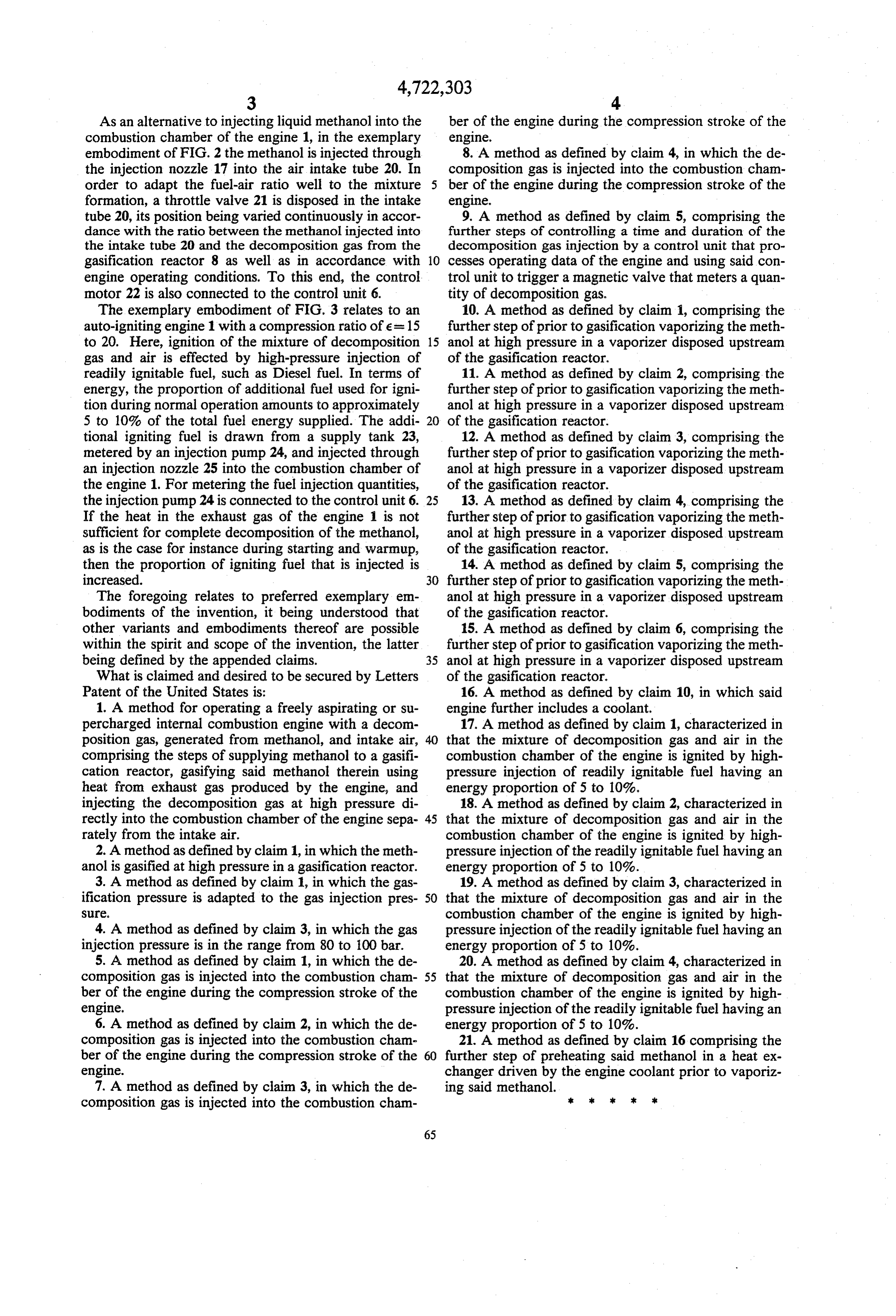
As an alternative to injecting liquid methanol into the ber of the engine during the compression stroke of the combustion chamber of the engine 1, in the exemplary engine.
embodiment of FIG. 2 the methanol is injected through 8. A method as defined by claim 4, in which the de the injection nozzle 17 into the air intake tube 20. In composition gas is injected into the combustion cham order to adapt the fuel-air ratio well to the mixture ber of the engine during the compression stroke of the formation, a throttle valve 21 is disposed in the intake engine.
tube 20, its position being varied continuously in accor 9. A method as defined by claim 5, comprising the dance with the ratio between the methanol injected into further steps of controlling a time and duration of the the intake tube 20 and the decomposition gas from the decomposition gas injection by a control unit that pro gasification reactor 8 as well as in accordance with O cesses operating data of the engine and using said con engine operating conditions. To this end, the control trol unit to trigger a magnetic valve that meters a quan motor 22 is also connected to the control unit 6. tity of decomposition gas.
The exemplary embodiment of FIG.3 relates to an 10. A method as defined by claim 1, comprising the auto-igniting engine 1 with a compression ratio of e = 15 further step of prior to gasification vaporizing the meth to 20. Here, ignition of the mixture of decomposition 15 anol at high pressure in a vaporizer disposed upstream gas and air is effected by high-pressure injection of of the gasification reactor.
readily ignitable fuel, such as Diesel fuel. In terms of 11. A method as defined by claim 2, comprising the energy, the proportion of additional fuel used for igni further step of prior to gasification vaporizing the meth tion during normal operation amounts to approximately anol at high pressure in a vaporizer disposed upstream 5 to 10% of the total fuel energy supplied. The addi 20 of the gasification reactor.
tional igniting fuel is drawn from a supply tank 23, 12. A method as defined by claim 3, comprising the metered by an injection pump 24, and injected through further step of prior to gasification vaporizing the meth an injection nozzle 25 into the combustion chamber of anol at high pressure in a vaporizer disposed upstream the engine 1. For metering the fuel injection quantities, of the gasification reactor.
the injection pump 24 is connected to the control unit 6. 25 13. A method as defined by claim 4, comprising the If the heat in the exhaust gas of the engine 1 is not further step of prior to gasification vaporizing the meth sufficient for complete decomposition of the methanol, anol at high pressure in a vaporizer disposed upstream as is the case for instance during starting and warmup, of the gasification reactor.
then the proportion of igniting fuel that is injected is 14. A method as defined by claim 5, comprising the increased. further step of prior to gasification vaporizing the meth The foregoing relates to preferred exemplary en anol at high pressure in a vaporizer disposed upstream bodiments of the invention, it being understood that of the gasification reactor.
other variants and embodiments thereof are possible 15. A method as defined by claim 6, comprising the within the spirit and scope of the invention, the latter further step of prior to gasification vaporizing the meth being defined by the appended claims. 35 anol at high pressure in a vaporizer disposed upstream What is claimed and desired to be secured by Letters of the gasification reactor.
Patent of the United States is: 16. A method as defined by claim 10, in which said 1. A method for operating a freely aspirating or su engine further includes a coolant.
percharged internal combustion engine with a decom 17. A method as defined by claim 1, characterized in position gas, generated from methanol, and intake air, that the mixture of decomposition gas and air in the comprising the steps of supplying methanol to a gasifi combustion chamber of the engine is ignited by high cation reactor, gasifying said methanol therein using pressure injection of readily ignitable fuel having an heat from exhaust gas produced by the engine, and energy proportion of 5 to 10%.
injecting the decomposition gas at high pressure di 18. A method as defined by claim 2, characterized in rectly into the combustion chamber of the engine sepa 45 that the mixture of decomposition gas and air in the rately from the intake air. combustion chamber of the engine is ignited by high 2. A method as defined by claim 1, in which the meth pressure injection of the readily ignitable fuel having an anol is gasified at high pressure in a gasification reactor. energy proportion of 5 to 10%.
3. A method as defined by claim 1, in which the gas 19. A method as defined by claim 3, characterized in ification pressure is adapted to the gas injection pres 50 that the mixture of decomposition gas and air in the Se combustion chamber of the engine is ignited by high 4. A method as defined by claim 3, in which the gas pressure injection of the readily ignitable fuel having an injection pressure is in the range from 80 to 100 bar. energy proportion of 5 to 10%. 5. A method as defined by claim 1, in which the de 20. A method as defined by claim 4, characterized in composition gas is injected into the combustion cham 55 that the mixture of decomposition gas and air in the ber of the engine during the compression stroke of the combustion chamber of the engine is ignited by high engine. pressure injection of the readily ignitable fuel having an 6. A method as defined by claim 2, in which the de energy proportion of 5 to 10%.
composition gas is injected into the combustion cham 21. A method as defined by claim 16 comprising the ber of the engine during the compression stroke of the 60 further step of preheating said methanol in a heat ex engine. changer driven by the engine coolant prior to vaporiz 7. A method as defined by claim 3, in which the de ing said methanol.
composition gas is injected into the combustion cham s sk
Provenance
- Collection
- Cited prior art
- Original PDF
- patentimages.storage.googleapis.com →
- Filed
- 1986-06-10
- Pages
- 6
- Method
- pdftotext (the PDF's own text layer) + pdftoppm 300dpi page scans
- Source
- Google Patents bibliographic record
- Granted
- 1988-02-02
- Inventors
- Rolf Leonhard; Robert Bosch GmbH
- Transcribed from
- patentimages.storage.googleapis.com →