patent · US4604867
Method and apparatus for implementing a thermodynamic cycle with intercooling
12 August 1986
Page 1 — bibliographic record
United States Patent (19) 11 Patent Number: 4,604,867 Kalina 45) Date of Patent: Aug. 12, 1986 (54) METHOD AND APPARATUS FOR Attorney, Agent, or Firm-Arnold, White & Durkee MPLEMENTING ATHERMODYNAMIC (57) ABSTRACT
CYCLE WITH INTERCOOLNG
A method and apparatus for implementing a thermody 76 Inventor: Alexander I. Kalina, 12214 Clear namic cycle with intercooling, includes a condensing Fork, Houston, Tex. 77077 subsystem, a boiler, and a turbine. The boiler may in (21) Appl. No.: 705,906 clude a preheater, an evaporator, and a superheater. (22 Filed: Feb. 26, 1985 After initial expansion in the turbine, the fluid may be diverted to a reheater to increase the temperature avail 51) Int. C. ......................... F01K 7/38; F01K 25/00 able for superheating. After return to the turbine and 52 U.S. C. ........................................ 60/653; 60/670; additional expansion, the fluid may be withdrawn from 60/649 the turbine and cooled in an intercooler. Thereafter the 58) Field of Search ................. 60/653, 670, 677, 678, fluid is returned to the turbine for additional expansion. 60/679, 649, 673 The cooling of the turbine gas may provide additional 56 References Cited heat for evaporation. Intercooling may provide com
vide recuperation of available heat which would other 3,979,914 9/1976 Weber ................................... 60/678 wise remain unused following final turbine expansion. 4,433,545 2/1984 Chang ................................... 60/677
Primary Examiner-Allen M. Ostrager 30 Claims, 4 Drawing Figures
Page 2
Drawing sheet — no readable text.
Page 3
Drawing sheet — no readable text.
Page 4
Drawing sheet — no readable text.
Page 5
source and the working fluid in the boiler. Simply put,
METHOD AND APPARATUS FOR for any given enthalpy the temperature of the heat IMPLEMENTING ATHERMODYNAMIC CYCLE source is always greater than the temperature of the WITH INTERCOOLING working fluid. Ideally, this temperature difference would be almost, but not quite, zero.
BACKGROUND OF THE INVENTION This mismatch occurs both in the classical Rankine 1. Field of the Invention cycle, using a pure substance as a working fluid, as well This invention relates generally to methods and appa as in the Kalina and Exergy cycles described above, ratus for transforming energy from a heat source into usingasa amixture as the working fluid. The use of a mix usable form using a working fluid that is expanded and 10 ture working fluid in the manner of the Kalina and regenerated. This invention further relates to a method Exergy cycles reduces these losses to a significant ex and apparatus for improving the heat utilization effi tent. However, it would be highly desirable to further ciency of a thermodynamic cycle. reduce these losses in any cycle. 2. Brief Description of the Background Art In the conventional Rankine cycle, the losses arising In the Rankine cycle, a working fluid such as water, 15 from mismatching of the enthalpy-temperature charac ammonia or a freon is evaporated in an evaporator teristics of the heat source and the working fluid would utilizing an available heat source. The evaporated gase constitute about 25% of the available exergy. With a ous working fluid is expanded across a turbine to trans cycle such as that described in U.S. Pat. No. 4,489,563, form its energy into usable form. The spent gaseous 20 the loss of exergy in the boiler due to enthalpy-tempera working fluid is then condensed in a condenser using an ture characteristics mismatching would constitute about available cooling medium. The pressure of the con 14% of all of the available exergy.
densed working medium is increased by pumping, fol The overall boiling process in a thermodynamic cycle lowed by evaporation and so on to continue the cycle. can be viewed for discussion purposes as consisting of The Exergy cycle, described in U.S. Pat. No. three distinct parts: preheating, evaporation, and super 4,346,561, utilizes a binary or multi-component working 25 heating. With conventional technology, the matching fluid. This cycle operates generally on the principle that of a heat source and the working fluid is reasonably a binary working fluid is pumped as a liquid to a high adequate during preheating. However, the quantity of working pressure and is heated to partially vaporize the heat in the temperature range suitable for superheating working fluid. The fluid is then flashed to separate high is generally much greater than necessary, while the and low boiling working fluids. The low boiling compo 30 quantity of heat in the temperature range suitable for nent is expanded through a turbine, to drive the turbine, evaporation is much smaller than necessary. The inven while the high boiling component has heat recovered tor of the present invention has appreciated that a por for use in heating the binary working fluid prior to tion of the high temperature heat which would be suit evaporation. The high boiling component is then mixed able for high temperature superheating is used for evap with the spent low boiling working fluid to absorb the 35 spent working fluid in a condenser in the presence of a oration very in previously known processes. This causes large temperature differences between the two cooking medium. streams, and as a result, irreversible losses of exergy. The theoretical comparison of the conventional Ran kine cycle and the Exergy cycle demonstrates the im ingThese irreversible losses may be lessened by reheat the stream of working fluid after it has been partially proved efficiency of the new cycle over the Rankine 40 expanded in a turbine. However, reheating results in cycle when an available, relatively low temperature repeated superheating.
heat source such as ocean water, geothermal energy or the necessary quantity As of a result, reheating increases heat for superheating. This the like is employed. increase in the required heat provides better matching In applicant's further invention, referred to as the between the heat source and the working fluid enthal Basic Kalina cycle, the subject of U.S. Pat. No. 45 py-temperature characteristics. However, reheating has 4,489,563, relatively lower temperature available heat is no beneficial effect with respect to the quantity of heat utilized to effect partial distillation of at least a portion necessary for evaporation. Thus, the total quantity of of a multi-component fluid stream at an intermediate heat necessary per unit of weight of working fluid sig pressure to generate working fluid fractions of differing nificantly increases with reheating. Therefore, the total compositions. The fractions are used to produce at least 50 weight flow rate of working fluid through the boiler one main rich solution which is relatively enriched with respect to the lower boiling component, and to produce turbine is reduced. Thus, the benefits of reheating are largely transitory in that the reduced weight flow rate one lean solution which is relatively impoverished with limits the possible increase in overall efficiency that respect to the lower boiling component. The pressure of the main rich solution is increased; thereafter, it is evap 55 may be derived.
orated to produce a charged gaseous main working The ideal solution to the age old dilemma of poorly fluid. The main working fluid is expanded to a low matched heat source and working fluid enthalpy-tem pressure level to convert energy to usable form. The perature characteristics would be one that makes high spent low pressure level working fluid is condensed in a in temperature heat available from the heat source for use main absorption stage by dissolving with cooling in the 60 superheating thereby reducing the temperature dif lean solution to regenerate an initial working fluid for ferences during superheating, but at the same time pro reuse, vides lower temperature heat which minimizes the tem In any process of converting thermal energy to a perature differences in the process of evaporation. It usable form, the major loss of available energy in the should be evident that these two goals are apparently heat source occurs in the process of boiling or evaporat 65 mutually inconsistent since increasing the superheating ing the working fluid. This loss of available energy heat would appear to require either increasing the over (known as exergy or essergy) is due to the mismatch of all heating source temperature or using reheating. As the enthalpy-temperature characteristics of the heat discussed above, reheating has certain drawbacks,
Page 6
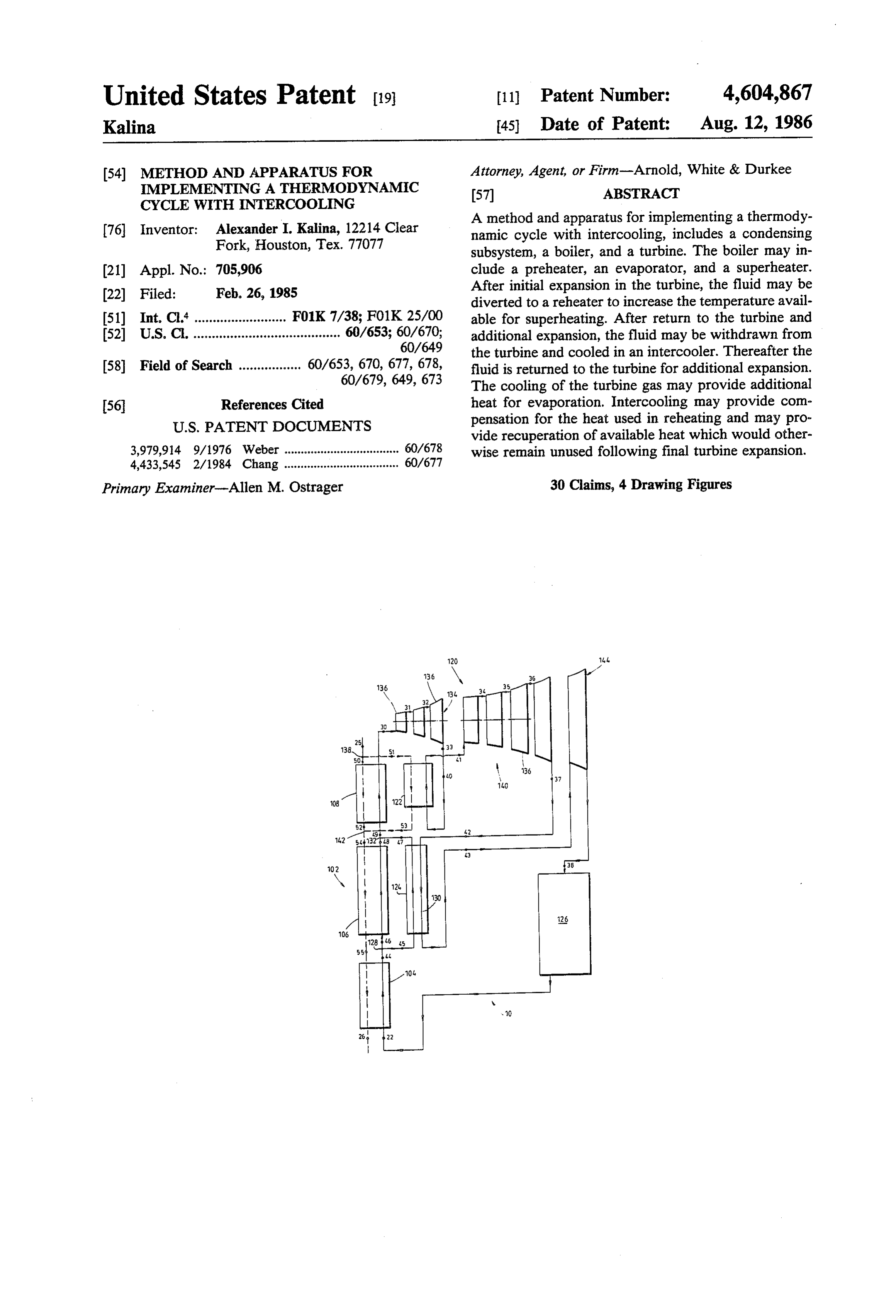
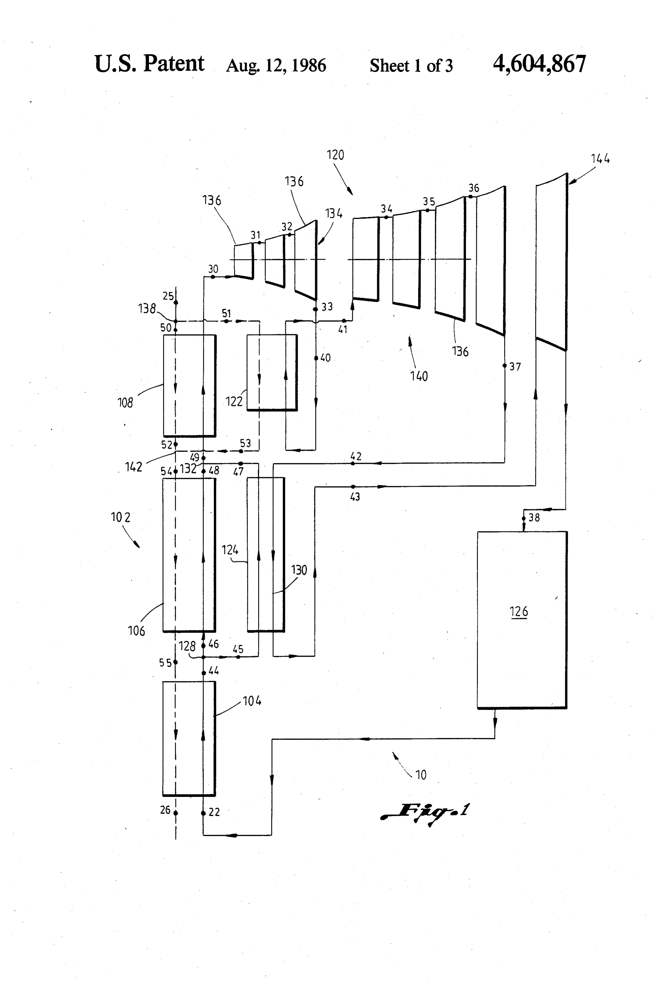
which to a large degree mitigate the partly transitory In accordance with still another embodiment of the gains achieved. present invention, an apparatus for implementing a ther Moreover, the greater the available heat for super modynamic cycle includes a turbine device. The turbine heating, the greater would be the output temperature of device has first and second turbine sets each including the gaseous spent working fluid from the turbine. This is 5 at least one turbine stage. Each of the turbine sets has a undesirable from an efficiency standpoint since the su gas inlet and a gas outlet. A turbine gas cooler is con perheating of the exiting steam makes subsequent con nected between the gas outlet of the first set and the gas densing more difficult and causes additional losses of inlet of the second set, such that most of the fluid pass exergy. Thus, any effort to improve efficiency with ing through the turbine would pass through the turbine respect to one part of the cycle seems to eventually 10 gas cooler and then back to said turbine device. cause lower efficiency in another part of the cycle. BRIEF DESCRIPTION OF THE DRAWING SUMMARY OF THE INVENTION FIG. 1 is a schematic representation of one system for It is one feature of the present invention to provide a carrying out one embodiment of the method and appa significant improvement in the efficiency of a thermo 15 ratus of the present invention;
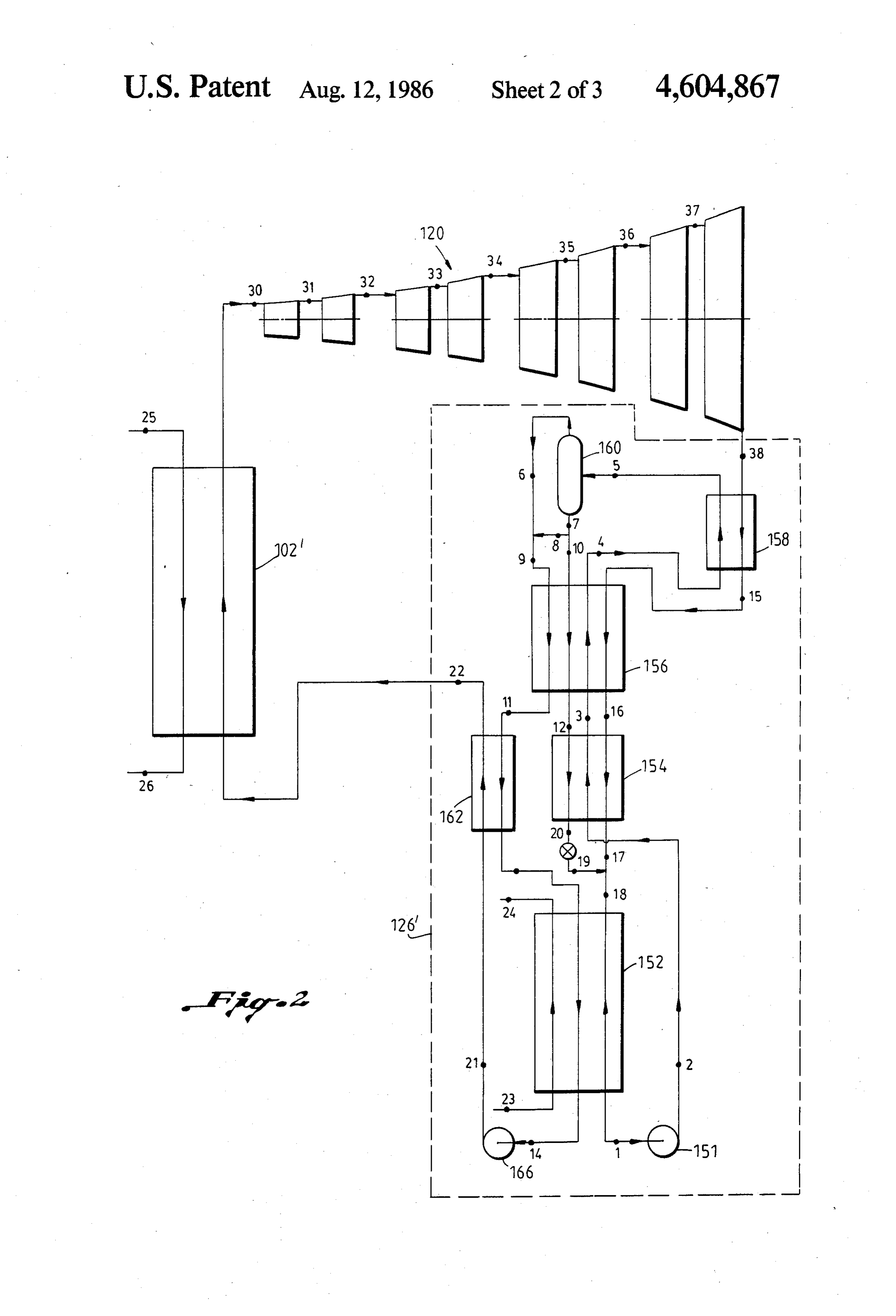
dynamic cycle by permitting closer matching of the FIG. 2 is a schematic representation of one exem working fluid and the heat source enthalpy-temperature plary embodiment of Applicant's previous invention, characteristics in the boiler. It is also a feature of the showing within dashed lines a schematic representation present invention to provide a system which both in of one exemplary condensing subsystem for use in the creases the efficiency of superheating while providing 20 system shown in FIG. 1;
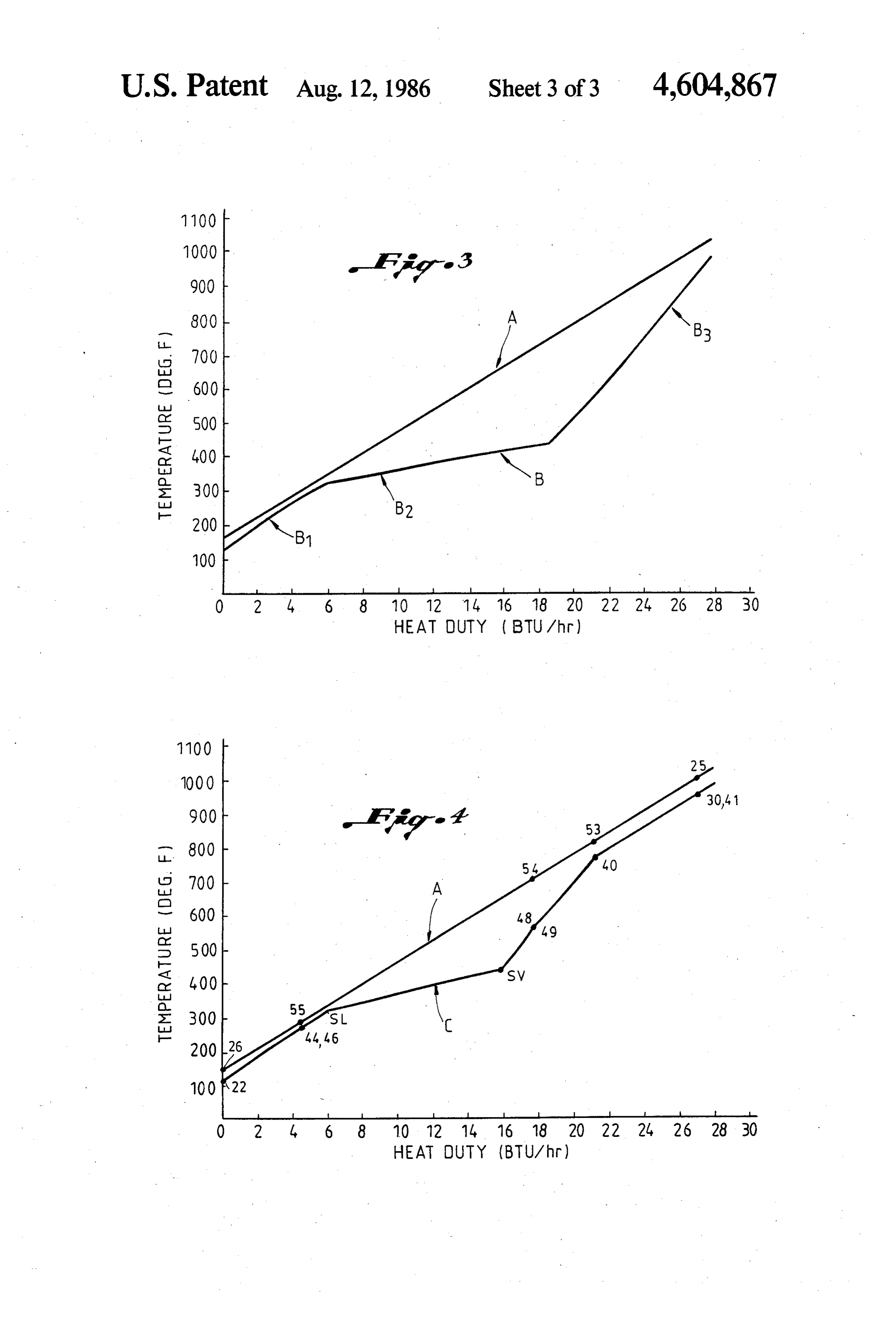
concommitant advantages during evaporation. Another FIG. 3 is a graph of calculated temperature in degrees feature of the present invention is to enable these advan Fahrenheit versus boiler heat duty or enthalpy in BTU's tages to be attained without necessarily adversely re per hour for the exemplary embodiment of Applicant's ducing the mass flow rate of the cycle. previous invention shown in FIG. 2; and In accordance with one embodiment of the present 25 FIG. 4 is a graph of calculated temperature in degrees invention, a method of implementing a thermodynamic Fahrenheit versus boiler heat duty or enthalpy in BTU's cycle includes the step of expanding a gaseous working per hour in accordance with one exemplary embodi fluid to transform its energy into a usable form. The ment of the present invention.
expanded gaseous working fluid is cooled and subse DESCRIPTION OF A PREFERRED quently expanded to a spent low pressure level to trans 30 EMBODIMENT form its energy into a usable form. The spent working fluid is condensed. The condensed fluid is then evapo Referring to the drawing wherein like reference char rated using the heat transferred during the cooling of acters are utilized for like parts throughout the several the expanded gaseous working fluid. views, a system 10, shown in FIG. 1, implements a In accordance with another embodiment of the pres 35 thermodynamic cycle, in accordance with one embodi ent invention, a method of implementing a thermody ment of the present invention. The system 10 includes a namic cycle includes the step of superheating an evapo boiler 102, in turn made up of a preheater 104, an evapo rated working fluid. The superheated fluid is expanded rator 106, and a superheater 108. In addition, the system to transform its energy into usable form. The expanded 10 includes a turbine 120, a reheater 122, an intercooler fluid is then reheated and subsequently further ex 40 124, and a condensing subsystem 126. panded to transform additional energy into a usable The condenser 126 may be any type of known heat form. The expanded, reheated fluid is cooled and again rejection device. In the Rankine cycle, heat rejection expanded, this time to a spent low pressure level to occurs in a simple heat exchanger and thus, for Rankine transform its energy into a usable form. The spent applications, the condensing subsystem 126 may take working fluid is condensed and subsequently evapo 45 the form of a heat exchanger or condenser. In the rated using heat transferred during cooling from the Kalina cycle, described in U.S. Pat. No. 4,489,563 to expanded, reheated fluid. Kalina, the heat rejection system requires that gases In accordance with yet another embodiment of the leaving the turbine be mixed with a multi-component present invention, a method for implementing a thermo fluid stream, for example, comprised of water and am dynamic cycle includes the step of preheating an initial 50 monia, condensed and then distilled to produce the working fluid to a temperature approaching its boiling original state of the working fluid. Thus, when the pres temperature. The preheated initial working fluid is split ent invention is used with a Kalina cycle, the distillation into first and second fluid streams. The first fluid stream subsystem described in U.S. Pat. No. 4,489,563 may be is evaporated using a first heat source while a second utilized as the condensing subsystem 126. U.S. Pat. No. fluid stream is evaporated using a second heat source. 55 4,489,563 is hereby expressly incorporated by reference The first and second evaporated fluid streams are com herein.
bined and subsequently superheated to produce a Various types of heat sources may be used to drive charged gaseous main working fluid. The charged gase the cycle of this invention. Thus, for example, heat ous main working fluid is expanded to transform its sources with temperatures as high as, say 1000 C. or energy into a usable form. Then the expanded, charged 60 more, down to low heat sources such as those obtained main working fluid is reheated and again expanded. The from ocean thermal gradients may be utilized. Heat expanded, reheated, charged main working fluid is sources such as, for example, low grade primary fuel, cooled to provide the heat source for evaporating the waste heat, geothermal heat, solar heat or ocean ther second fluid stream. The cooled main working fluid is mal energy conversion systems may be implemented again expanded, this time to a spent low pressure level 65 with the present invention.
to transform its energy into a usable form. The spent A variety of working fluids may be used in conjunc main working fluid is cooled and condensed to form the tion with this system depending on the kind of condens intial working fluid. ing subsystem 126 utilized. In conjunction with a con
Page 7
densing subsystem 126 as described in the U.S. patent each of the turbine sets described herein may be varied incorporated by reference herein, any multi-component widely depending on particular circumstances. working fluid that comprises a lower boiling point fluid The working fluid in the second turbine set 140 is and a relatively higher boiling point fluid may be uti expanded from the first intermediate pressure to a sec lized. Thus, for example, the working fluid employed ond intermediate pressure, thus generating power. The may be an ammonia-water mixture, two or more hydro total stream of working fluid is then sent to the inter carbons, two or more freons, mixtures of hydrocarbons cooler 124 where it is cooled, providing the heat neces and freons or the like. In general, the fluid may be mix sary for the evaporation of the second working fluid tures of any number of compounds with favorable ther stream. The intercooler 124 may be a simple heat ex modynamic characteristics and solubility. However, 10 changer. The fluid stream travels along the line 130 to when implementing the conventional Rankine cycle, a the last turbine set 144.
conventional single component working fluid such as The last turbine set 144 is illustrated as having only a water, ammonia, or freon may be utilized. single stage 136. However, the number of stages in the As shown in FIG. 1, a completely condensed work last turbine set 144 may be subject to considerable varia ing fluid passes through a preheater 104 where it is 15 tion depending on specific circumstances. The working heated to a temperature a few degrees below its boiling fluid expands to the final spent fluid pressure level thus temperature. This preheating is provided by the cooling producing additional power. From the last turbine set of all streams of a heat source indicated in dashed lines 144 the fluid stream is passed through the condensing through the preheater 104. The working fluid which subsystem 126 where it is condensed, pumped to a exits the preheater 104 is divided at point 128 into two 20 higher pressure and sent to the preheater 104 to con separate streams. tinue the cycle.
A first stream, separated at point 128, enters the evap A Kalina cycle condensing subsystem 126", shown in orator 106 while the second stream enters the inter FIG. 2, may be used as the condensing subsystem 126 in cooler 124. The first stream is heated in the evaporator the system shown in FIG. 1. In analyzing the condens 106 by the countercurrent heating fluid flow indicated 25 ing subsystem 126, it is useful to commence with the in dashed lines through the evaporator 106 and commu point in the subsystem identified by reference numeral 1 nicating with the heating fluid flow through the pre comprising the initial composite stream having an initial heater 104. The second fluid stream passing through the composition of higher and lower boiling components in intercooler 124 is heated by the fluid flow proceeding the form of ammonia and water. At point 1 the initial along line 130. Both the first and second streams are 30 composite stream is at a spent low pressure level. It is completely evaporated and initially superheated. Each pumped by means of a pump 151 to an intermediate of the streams has approximately the same pressure and pressure level where its pressure parameters will be as temperature but the streams may have different flow at point 2 following the pump 151.
rates. The fluid streams from the evaporator 106 and From point 2 of the flow line, the initial composite intercooler 124 are then recombined at point 132. 35 stream at an intermediate pressure is heated consecu The combined stream of working fluid is sent into the tively in the heat exchanger 154, in the recuperator 156 superheater 108 where it is finally superheated by heat and in the main heat exchanger 158. exchange with only part of the heat source stream indi The initial composite stream is heated in the heat cated by dashed lines extending through the super exchanger 154, in the recuperator 156 and in the main heater 108. Thus, the heat source stream extending from 40 heat exchanger 158 by heat exchange with the spent point 25 to point 26 passes first through the superheater composite working fluid from the turbine 120". When 108, then through the evaporator 106 and finally the system of FIG. 1 is being implemented with the through the preheater 104. The enthalpy-temperature condensing subsystem 126 the turbine 120 may be used characteristics of the illustrated heating fluid stream, 45 in place of the turbine 120". In addition, in the heat indicated by the line A in FIG. 4, is linear. exchanger 154 the initial composite stream is heated by From the superheater 108, the total stream of work the condensation stream as will be hereinafter de ing fluid enters the first turbine set 134 of turbine 120. scribed. In the recuperator 156 the initial composite The turbine set 134 includes one or more stages 136 and, stream is further heated by the condensation stream and in the illustrated embodiment, the first turbine set 134 by heat exchange with lean and rich working fluid frac includes three stages 136. In the first turbine set 134 the 50 tions as will be hereinafter described. working fluid expands to a first intermediate pressure The heating in the main heat exchanger 158 is per thereby converting thermal energy into mechanical formed only by the heat of the flow from the turbine energy. outlet and, as such, is essentially compensation for The whole working fluid stream from the first turbine under recuperation.
set 134 is reheated in the reheater 122. The reheater 122 55 At point 5 between the main heat exchanger 158 and is a conventional superheater or heat exchanger. With the separator stage 160 the initial composite stream has this reheating process the remaining portion of the heat been subjected to distillation at the intermediate pres source stream, split at point 138 from the flow from sure in the distillation system comprising the heat ex point 25 to point 26, is utilized. Having been reheated to changers 154 and 158 and the recuperator 156. If de a high temperature, the stream of working fluid leaves 60 sired, auxiliary heating means from any suitable or the reheater 122 and travels to the second turbine set available heat source may be employed in any one of the 140. At the same time the heating fluid flow from point heat exchangers 154 or 158 or in the recuperator 156. 51 to point 53 is returned to the main heating fluid flow At point 5 the initial composite stream has been par at point 142 to contribute to the processes in the evapo tially evaporated in the distillation system and is sent to rator 106 and preheater 104. The second turbine set 140 65 the gravity separator stage 160. In this stage 160 the may include a number of stages 136. In the illustrated enriched vapor faction which has been generated in the embodiment, the second turbine set 140 is shown as distillation system, and which is enriched with the low having four stages, however, the number of stages in boiling component, namely ammonia, is separated from
Page 8
the remainder of the initial composite stream to produce of the working fluid to accommodate the higher tem an enriched vapor fraction at point 6 and a stripped perature reheating process.
liquid fraction at point 7 from which the enriched vapor The parameters of flow at points 40, 41, 42 and 43 are fraction has been stripped. design variables and can be chosen in a way to obtain Further, the stripped liquid fraction from point 7 is the maximum advantage from the system 10. One divided into first and second stripped liquid fraction skilled in the art will be able to select the design vari streams having parameters as at points 8 and 10 respec ables to maximize performance under the various cir tively. cumstances that may be encountered. The enriched fraction at point 6 is enriched with the 10 The parameters of the various process points, shown lower boiling component, namely ammonia, relatively in FIG. 1, are subject to considerable variation depend to a lean working fluid fraction as discussed below. ing on specific circumstances. However, as a general The first enriched vapor fraction stream from point 6 type, itorcanrulebeofpointed guide thumb to the design of systems of this out that it may often be advanta is mixed with the first stripped liquid fraction stream at geous to make the temperature at point 40 as close as point 8 to provide a rich working fluid fraction at point 15 possible to the temperature of point 37 so that the effi
The rich working fluid fraction is enriched relatively ciencies of the first turbine set 134 and the second tur to the composite working fluid (as hereinafter dis bine set 140 are close to equal. In addition, it may be desirable in many situations to design the system so that cussed) with the lower boiling component comprising the temperature at point 42 is generally higher than the ammonia. The lean working fluid fraction, on the other 20 temperature of the saturated vapor of the working fluid hand, is impoverished relatively to the composite work in the evaporator 106. It may also often be desirable to ing fluid (as hereinafter discussed) with respect to the make the temperature at point 43 generally higher than lower boiling component.
The second stripped liquid fraction at point 10 com fluid in the boiler 102. saturated liquid of the working the temperature of a prises the remaining part of the initial composite stream 25 While a single pressure in the evaporator 106 and and is used to constitute the condensation stream.
The rich working fluid fraction at point 9 is partially intercooler one skilled 124 is utilized in the illustrated embodiment, in the art will appreciate that dual, triple condensed in the recuperator 156 to point 11. Thereaf and even higher numbers of boiler pressures may be ter the rich working fluid fraction is further cooled and selected for specific circumstances. The present inven condensed in the preheater 162 (from point 11 to 13), 30 tion is also applicable to multiple boiling cycles. While and is finally condensed in the absorption stage 152 by special advantages may be achieved through the use of means of heat exchange with a cooling water supply intercooler 124 heat in the evaporation process, the use through points 23 to 24. of the intercooler 124 between turbine sets can be ap The rich working fluid fraction is pumped to a plied to any portion of a thermodynamic system where charged high pressure level by means of the pump 166. 35 there is a shortage of adequate temperature heat. Inter Thereafter it passes through the preheater 162 to arrive cooling could provide heat to supplement boiling or to at point 22. From point 22 it may continue through the supplement heating in a superheater. system shown in FIG. 1. It should be understood that the present invention is When a Kalina cycle is implemented, the composite not limited to the use of intercooling in combination working fluid at point 38 exiting from the turbine 120 with reheating. Although this combination results in has such a low pressure that it cannot be condensed at significant advantages, many advantages can be this pressure and at the available ambient temperature. achieved with intercooling without reheating. For ex From point 38 the spent composite working fluid flows ample, intercooling may be utilized without reheating through the main heat exchanger 158, through the recu whenever the fluid exiting from the final turbine stage is perator 156 and through the heat exchanger 154. Here it 45 superheated. In general, it is important that intercooling is partially condensed and the released heat is used to be taken between turbine stages in order to obtain a preheat the incoming flow as previously discussed. sufficiently high fluid temperature. The spent composite working fluid at point 17 is then It is generally advantageous that at least most of the mixed with the condensation stream at point 19. At fluid flow through the turbine be passed through the point 19 the condensation stream has been throttled 50 intercooler. Even more advantageously, substantially from point 20 to reduce its presure to the low presure all of the flow through the turbine is passed through the level of the spent composite working fluid at point 17. intercooler. Advantageously, substantially all of the The resultant mixture is then fed from point 18 through cooled fluid is returned to the turbine for further expan the absorption stage 152 where the spent composite SO.
working fluid is absorbed in the condensation stream to 55 The advantages of the present invention may be ap regenerate the initial composite stream at point 1. preciated by comparison of FIGS. 3 and 4. In FIG.3 a The intercooling process accomplished by the inter boiler heat duty cycle for a thermodynamic cycle is cooler 124, shown in FIG. 1, reduces the output of the illustrated for a system of the type shown in FIG. 2, last turbine stage per pound of working fluid. However, pursuant to the teachings of U.S. Pat. No. 4,489,563, intercooling also enables reheating without sacrificing 60 previously incorporated herein. The heat source is indi the quantity of working fluid per pound. Thus, com cated by the line A while the working fluid is indicated pared to reheating without intercooling, the use of in by the line B. The enthalpy-temperature characteristics tercooling achieves significant advantages. of the working fluid during preheating are represented The heat returned by the intercooler 124 to the evap by the curve portion B1. Similarly, evaporation is indi oration process is advantageously approximately equal 65 cated by the portion B2 and superheating is indicated by the heat consumed in the reheater 122. This assures that the portion B3. The pinch point is located in the region the weight flow rate of the working fluid is restored. of the intersection of the portions B1 and B2. The extent Then it is not necessary to decrease the mass flow rate of the gap between the curves A and B represents irre
Page 9
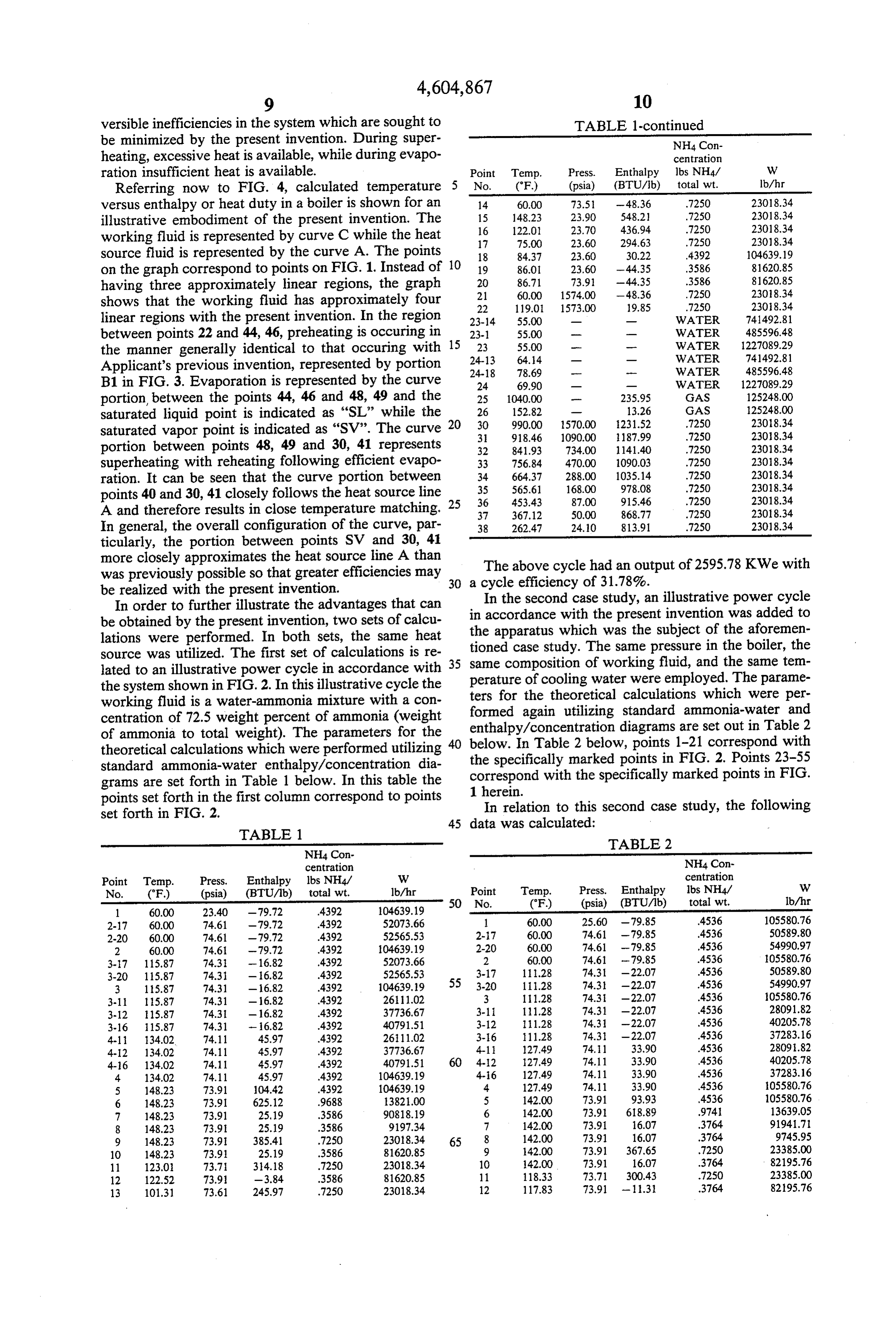
versible inefficiencies in the system which are sought to TABLE 1-continued be minimized by the present invention. During super NH4 Con heating, excessive heat is available, while during evapo centration ration insufficient heat is available. Point Temp. Press. Enthalpy lbs NH4/ W Referring now to FIG. 4, calculated temperature 5 No. (°F) (psia) (BTU/lb) total wt. lb/hr versus enthalpy or heat duty in a boiler is shown for an 14
illustrative embodiment of the present invention. The 16 122.01 23.70 436.94 .7250 23018.34 working fluid is represented by curve C while the heat 17 75.00 23.60 2.94.63 7250 23018.34 source fluid is represented by the curve A. The points 18 8437 23.60 30.22 4392 104639.19 on the graph correspond to points on FIG. 1. Instead of 10 19 86.0 23.60 - 44.35 .3586 81620.85 having three approximately linear regions, the graph 20
shows that the working fluid has approximately four 22 119.0 1573.00 9.85 .7250 2308.34 linear regions with the present invention. In the region 23-14 55.00 - WATER 74.1492.81 between points 22 and 44, 46, preheating is occuring in 23-1 55.00 - - WATER 485596.48 the manner generally identical to that occuring with 15 24-13 23 55.00 - - WATER 227089.29
Applicant's previous invention, represented by portion 24-18 64.14 78.69
WATER
WATER
B1 in FIG. 3. Evaporation is represented by the curve 24 69.90 - - WATER 1227089.29 portion, between the points 44, 46 and 48, 49 and the 25 1040.00 - 235.95 GAS 125248.00 saturated liquid point is indicated as "SL" while the 26 152.82 - 13.26 GAS 125248.00 saturated vapor point is indicated as "SV". The curve 20 3.30 990.00 1570.00
portion between points 48, 49 and 30, 41 represents 32 841.93 734.00 1141.40 .7250 23018.34 superheating with reheating following efficient evapo 33 756.84 470.00 1090.03 7250 2308.34 ration. It can be seen that the curve portion between 34 664.37 288.00 1035.14 .7250 2308.34 points 40 and 30, 41 closely follows the heat source line 25 3536 453.43
A and therefore results in close temperature matching, 37 367,12 50.00 868.77 .7250 2308.34 In general, the overall configuration of the curve, par 38 262.47 24.10 813.91 .7250 23018.34 ticularly, the portion between points SV and 30, 41 more closely approximates the heat source line A than The above cycle had an output of 2595.78 KWe with was previously possible so that greater efficiencies may 30 a cycle efficiency of 31.78%.
be realized with the present invention.
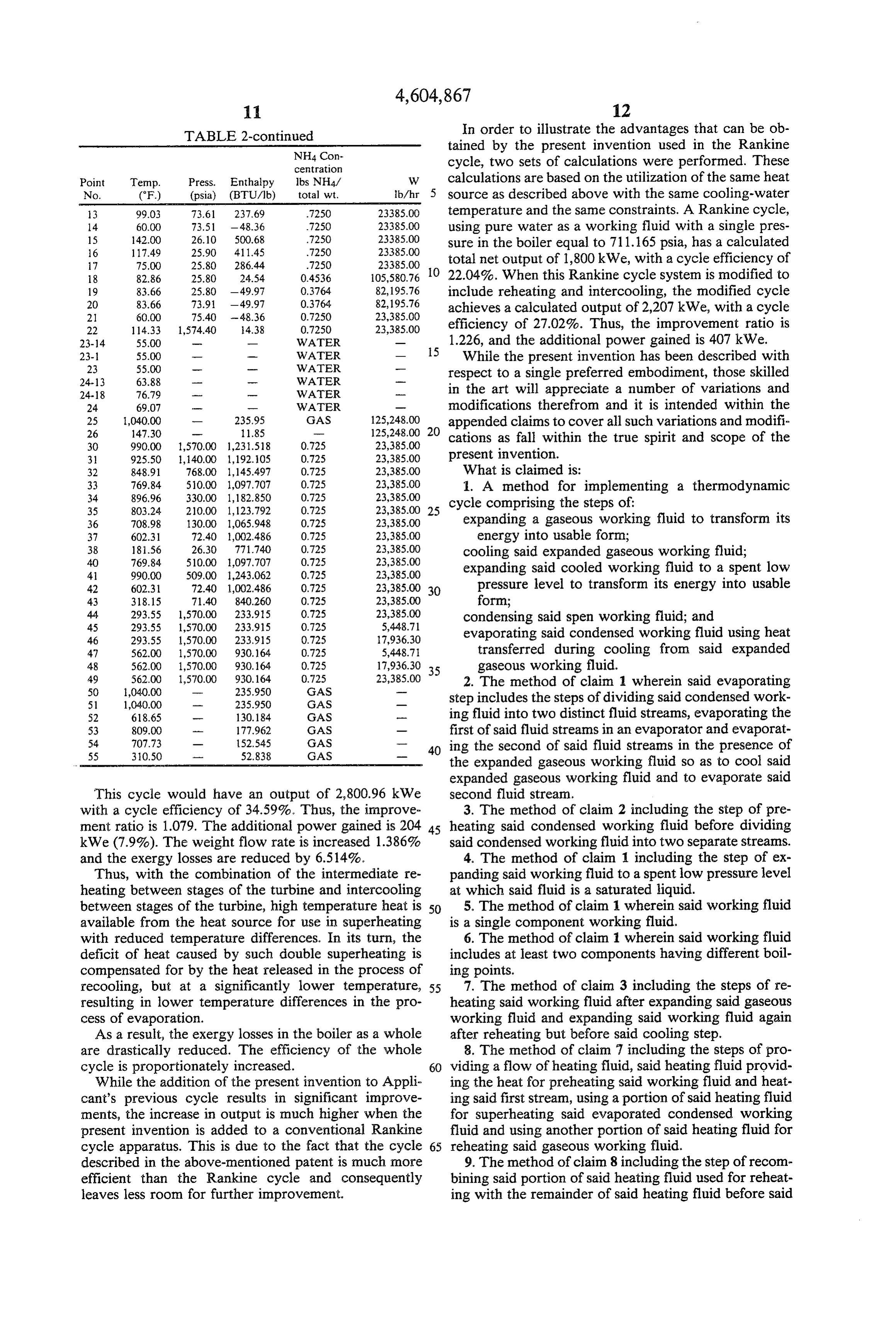
In order to further illustrate the advantages that can in In the second case study, an illustrative power cycle be obtained by the present invention, two sets of calcu theaccordance with the present invention was added to lations were performed. In both sets, the same heat tioned case study. Thewas apparatus which same the subject of the aforemen pressure in the boiler, the source was utilized. The first set of calculations is re 35 same composition of working fluid, and the same tem lated to an illustrative power cycle in accordance with the system shown in FIG. 2. In this illustrative cycle the perature of cooling water were employed. The parame working fluid is a water-ammonia mixture with a con formed againtheoretical ters for the calculations which were per utilizing standard ammonia-water and centration of 72.5 weight percent of ammonia (weight enthalpy/concentration of ammonia to total weight). The parameters for the 40 below. In Table 2 below,diagrams points are set out in Table 2 1-21 correspond with theoretical calculations which were performed utilizing standard ammonia-water enthalpy/concentration dia the specifically marked points in FIG. 2. Points 23-55 grams are set forth in Table 1 below. In this table the correspond with the specifically marked points in FIG. points set forth in the first column correspond to points 1 herein.
In relation to this second case study, the following set forth in FIG. 2.
data was calculated:
TABLE 2
NH4 Con centration NH4 Con
Point Temp. Press. Enthalpy lbs NH4/ W centration No. (F) (psia) (BTU/lb) total wt. 1b/hr Point Temp. Press. Enthalpy lbs NH4/ W
l 60.00 23.40 -79.72 4392 50 2-17 60.00 74.61 -79.72 4392 52073.66 1 60.00 25.60 - 79.85 4536 105580.76 2-20 60.00 74.61 -79.72 4392 52.565.53 2-17 60.00 74.61 - 79.85 4536 50589.80 2 60.00 74.6 -79.72 4392 104639.19 2-20 60.00 74.61 - 79.85 4536 54990.97 3.17 115.87 74.3 - 16.82 4392 52O73.66 2 60.00 74.61 - 79.85 4536 105580.76 3-20 115.87 74.31 - 6.82 .4392 52.565.53 3-17 11.28 74.31 -2207 4536 50589.80 3 15.87 74.31 - 16.82 4392 104639.19 55 3-20 11.28 74.31 -22.07 4536 54990.97 3-1 15.87 74.31 - 6.82 4392 261.02 3 11.28 74.3 - 22.07 4536 05580.76 3-12 15.87 74.3 - 16.82 4392 37736.67 3-1 11.28 74.31 - 22.07 4536 28091.82 3-16 15.87 74.31 - 6.82 4392 40791.51 3-12 111.28 74.31 -22.07 4536 40205.78 4-11 134.02 74.11 45.97 4392 26.11.02 3-6 11.28 74.3 - 22.07 4536 37283.16 4-12 134.02 74.11 45.97 4392 37736.67 4-1 127.49 74.1 33.90 4536 2809.82 4-16 134.02 74.11 45.97 4392 40791.51 60 4-12 127.49 74.11 33.90 4536 40205.78 4 134.02 74.11 45.97 4392 104639.19 4-6 127.49 74.11 33.90 4536 37283.16
12 122.52 73.9 -3.84 .3586 81620,85 11 118.33 73.71 300.43 .7250 23385.00 13 101.31 73.61 245.97 .7250 23018.34 12 117.83 73.91 - 1.3 3764 8295.76
Page 10
TABLE 2-continued In order to illustrate the advantages that can be ob NH4 Con tained by the present invention used in the Rankine centration cycle, two sets of calculations were performed. These
Point Temp. Press. Enthalpy Ibs NH4/ W calculations are based on the utilization of the same heat No. (°F) (psia) (BTU/lb) total wt. b/hr 5 source as described above with the same cooling-water 3 99.03 73.61 237.69 7250 23.385.00 temperature and the same constraints. A Rankine cycle, 14 60.00 73.51 - 48.36 7250 23385.00 using pure water as a working fluid with a single pres 15 4200 26.10 500.68 7250 23385.00 sure in the boiler equal to 711.165 psia, has a calculated 6 117.49 25.90 A1145 7250 23385.00 7 75.00 25.80 286.44 7250 23385.00 total net output of 1,800kWe, with a cycle efficiency of 18 82.86 25.80 24.54 0.4536 105,580.76 O 22.04%. When this Rankine cycle system is modified to 19 83.66 25.80 - 49.97 0.3764 82,195.76 include reheating and intercooling, the modified cycle 20 83.66 73.91 - 49.97 0.3764 82,195.76 achieves a calculated output of 2,207 kWe, with a cycle 21 60.00 75.40 - 48.36 0.7250 23,385.00 22 114.33 1,574.40 4.38 0.7250 23,385.00 efficiency of 27.02%. Thus, the improvement ratio is
1.226, and the additional power gained is 407 kWe.
23- 55.00 m- WATER While the present invention has been described with
WATER
WATER
respect to a single preferred embodiment, those skilled 24-18 76.79 WATER w in the art will appreciate a number of variations and 24 69,07 r -- WATER m modifications therefrom and it is intended within the
GAS
appended claims to cover all such variations and modific 30 99000 1,570.00 1,231.518 0.725 23,385.00 cations as fall within the true spirit and scope of the 3. 925.50 1,140.00 1,192.105 0.725 23,385.00 present invention.
32 848.91 768.00 1,145.497 0.725 23,385.00 What is claimed is:
1. A method for implementing a thermodynamic 35 8O3.24. 210.00 1,123.792 0.725 23,385.00 25 cycle comprising the steps of:
36 708.98 130.00 1,065.948 0.725 23,385.00 expanding a gaseous working fluid to transform its 37 602.31 72.40 1,002.486 0.725 23,385.00 energy into usable form;
38 1856 26.30 771,740 0.725 23,385.00 cooling said expanded gaseous working fluid; AO 769.84 510.00 1,097,707 0.725 23,385.00 41 99000 509.00 1,243.062 0.725 23,385.00 expanding said cooled working fluid to a spent low 42 602.31 72.40 1,002.486 0.725 23,385.00 30 pressure level to transform its energy into usable 43 318.15 71.40 840,260 0.725 23,385.00 form;
condensing said spen working fluid; and 46 293.55 1,570.00 233.915 0.725 17,936.30 evaporating said condensed working fluid using heat 47 562.00 1,570.00. 930, 164 0.725 5,448.71 transferred during cooling from said expanded 48 562.00 1,570.00 930, 164 0.725 17,936.30 35 gaseous working fluid.
GAS 23,385.00 2. The method of claim 1 wherein said evaporating 51 1,040.00 235.950 GAS step includes the steps of dividing said condensed work S2 618.65 ra 130.84 GAS ing fluid into two distinct fluid streams, evaporating the 53 809.00 177.962 GAS m first of said fluid streams in an evaporator and evaporat 40 ing the second of said fluid streams in the presence of 54 707.73 o 152,545 GAS ---
the expanded gaseous working fluid so as to cool said expanded gaseous working fluid and to evaporate said
This cycle would have an output of 2,800.96 kWe second fluid stream.
with a cycle efficiency of 34.59%. Thus, the improve 3. The method of claim 2 including the step of pre ment ratio is 1.079. The additional power gained is 204 45 heating said condensed working fluid before dividing kWe (7.9%). The weight flow rate is increased 1.386% said condensed working fluid into two separate streams. and the exergy losses are reduced by 6.514%. 4. The method of claim 1 including the step of ex Thus, with the combination of the intermediate re panding said working fluid to a spent low pressure level heating between stages of the turbine and intercooling at which said fluid is a saturated liquid.
between stages of the turbine, high temperature heat is SO 5. The method of claim 1 wherein said working fluid available from the heat source for use in superheating is a single component working fluid.
with reduced temperature differences. In its turn, the 6. The method of claim 1 wherein said working fluid deficit of heat caused by such double superheating is includes at least two components having different boil compensated for by the heat released in the process of ing points.
recooling, but at a significantly lower temperature, 55 7. The method of claim 3 including the steps of re resulting in lower temperature differences in the pro heating said working fluid after expanding said gaseous cess of evaporation. working fluid and expanding said working fluid again As a result, the exergy losses in the boiler as a whole after reheating but before said cooling step. are drastically reduced. The efficiency of the whole 8. The method of claim 7 including the steps of pro cycle is proportionately increased. 60 viding a flow of heating fluid, said heating fluid provid While the addition of the present invention to Appli ing the heat for preheating said working fluid and heat cant's previous cycle results in significant improve ing said first stream, using a portion of said heating fluid ments, the increase in output is much higher when the for superheating said evaporated condensed working present invention is added to a conventional Rankine fluid and using another portion of said heating fluid for cycle apparatus. This is due to the fact that the cycle 65 reheating said gaseous working fluid.
described in the above-mentioned patent is much more 9. The method of claim 8 including the step of recom efficient than the Rankine cycle and consequently bining said portion of said heating fluid used for reheat leaves less room for further improvement. ing with the remainder of said heating fluid before said
Page 11
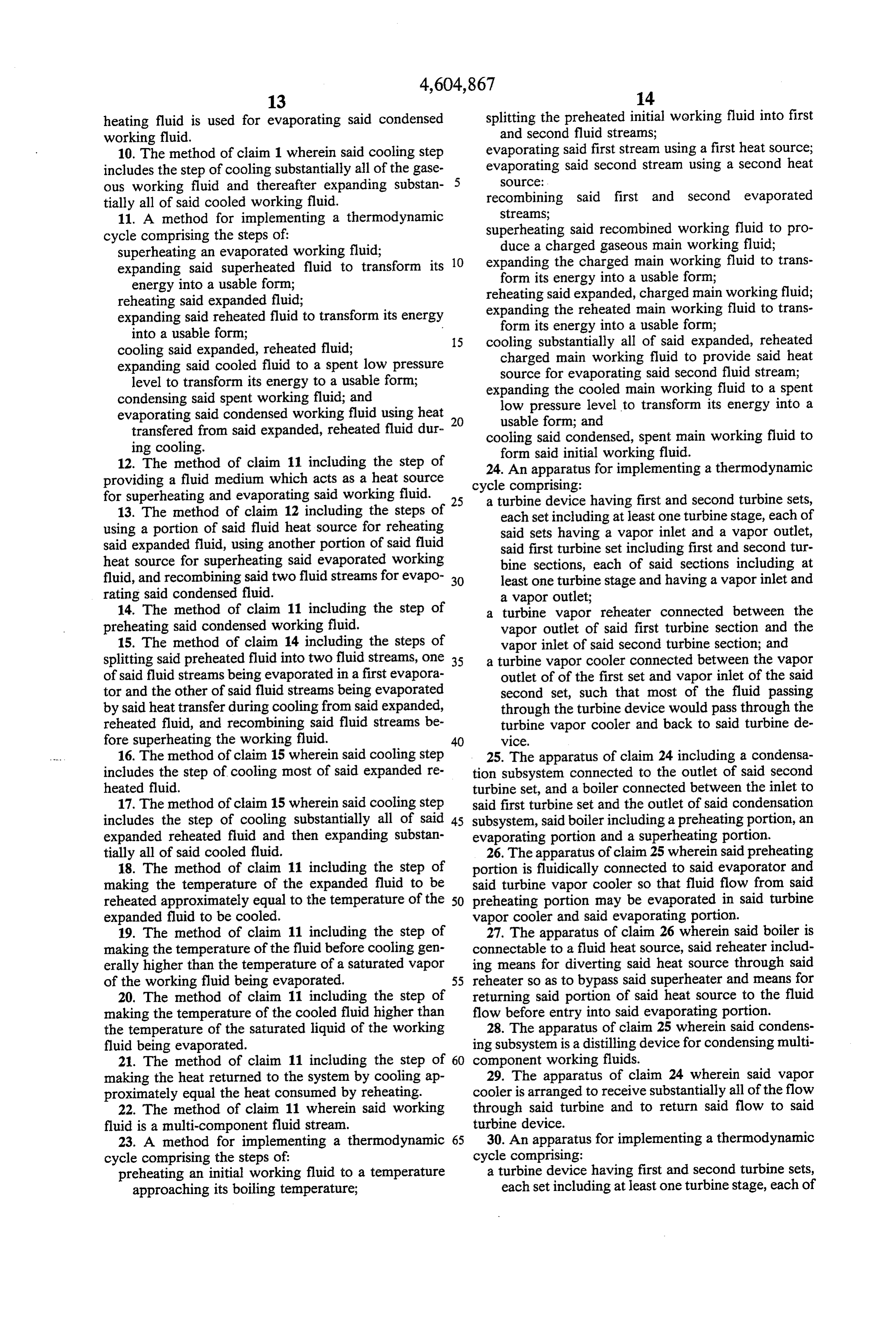
heating fluid is used for evaporating said condensed splitting the preheated initial working fluid into first working fluid. and second fluid streams; 10. The method of claim 1 wherein said cooling step evaporating said first stream using a first heat source; includes the step of cooling substantially all of the gase evaporating said second stream using a second heat ous working fluid and thereafter expanding substan- 5 SOUCe:
tially all of said cooled working fluid. recombining said first and second evaporated 11. A method for implementing a thermodynamic streams;
cycle comprising the steps of: superheating said recombined working fluid to pro superheating an evaporated working fluid; duce a charged gaseous main working fluid; expanding said superheated fluid to transform its 10 expanding the charged main working fluid to trans energy into a usable form; form its energy into a usable form; reheating said expanded fluid; reheating said expanded, charged main working fluid; expanding said reheated fluid to transform its energy expanding the reheated main working fluid to trans into a usable form; form its energy into a usable form; cooling said expanded, reheated fluid; 15 cooling substantially all of said expanded, reheated expanding said cooled fluid to a spent low pressure charged main working fluid to provide said heat level to transform its energy to a usable form; source for evaporating said second fluid stream; condensing said spent working fluid; and expanding the cooled main working fluid to a spent evaporating said condensed working fluid using heat 20 low pressure level to transform its energy into a transfered from said expanded, reheated fluid dur usable form; and ing cooling. cooling said condensed, spent main working fluid to 12. The method of claim 11 including the step of form said initial working fluid.
24. An apparatus for implementing a thermodynamic providing a fluid medium which acts as a heat source cycle comprising:
for superheating and evaporating said working fluid. 25 a turbine device having first and second turbine sets, 13. The method of claim 12 including the steps of each set including at least one turbine stage, each of using a portion of said fluid heat source for reheating said sets having a vapor inlet and a vapor outlet, said expanded fluid, using another portion of said fluid said first turbine set including first and second tur heat source for superheating said evaporated working bine sections, each of said sections including at fluid, and recombining said two fluid streams for evapo 30 least one turbine stage and having a vapor inlet and rating said condensed fluid. a vapor outlet;
14. The method of claim 11 including the step of a turbine vapor reheater connected between the preheating said condensed working fluid. vapor outlet of said first turbine section and the 15. The method of claim 14 including the steps of vapor inlet of said second turbine section; and splitting said preheated fluid into two fluid streams, one 35 a turbine vapor cooler connected between the vapor of said fluid streams being evaporated in a first evapora outlet of of the first set and vapor inlet of the said tor and the other of said fluid streams being evaporated second set, such that most of the fluid passing by said heat transfer during cooling from said expanded, through the turbine device would pass through the reheated fluid, and recombining said fluid streams be turbine vapor cooler and back to said turbine de fore superheating the working fluid. 40 vice.
16. The method of claim 15 wherein said cooling step 25. The apparatus of claim 24 including a condensa includes the step of cooling most of said expanded re tion subsystem connected to the outlet of said second heated fluid. turbine set, and a boiler connected between the inlet to 17. The method of claim 15 wherein said cooling step said first turbine set and the outlet of said condensation includes the step of cooling substantially all of said 45 subsystem, said boiler including a preheating portion, an expanded reheated fluid and then expanding substan evaporating portion and a superheating portion. tially all of said cooled fluid. 26. The apparatus of claim 25 wherein said preheating 18. The method of claim 11 including the step of portion is fluidically connected to said evaporator and making the temperature of the expanded fluid to be said turbine vapor cooler so that fluid flow from said reheated approximately equal to the temperature of the 50 preheating portion may be evaporated in said turbine expanded fluid to be cooled. vapor cooler and said evaporating portion. 19. The method of claim 11 including the step of 27. The apparatus of claim 26 wherein said boiler is making the temperature of the fluid before cooling gen connectable to a fluid heat source, said reheater includ erally higher than the temperature of a saturated vapor ing means for diverting said heat source through said of the working fluid being evaporated. 55 reheater so as to bypass said superheater and means for 20. The method of claim 11 including the step of returning said portion of said heat source to the fluid making the temperature of the cooled fluid higher than flow before entry into said evaporating portion. the temperature of the saturated liquid of the working 28. The apparatus of claim 25 wherein said condens fluid being evaporated. ing subsystem is a distilling device for condensing multi 21. The method of claim 11 including the step of 60 component working fluids.
making the heat returned to the system by cooling ap 29. The apparatus of claim 24 wherein said vapor proximately equal the heat consumed by reheating. cooler is arranged to receive substantially all of the flow 22. The method of claim 11 wherein said working through said turbine and to return said flow to said fluid is a multi-component fluid stream. turbine device.
23. A method for implementing a thermodynamic 65 30. An apparatus for implementing a thermodynamic cycle comprising the steps of: cycle comprising:
preheating an initial working fluid to a temperature a turbine device having first and second turbine sets, approaching its boiling temperature; each set including at least one turbine stage, each of
Page 12
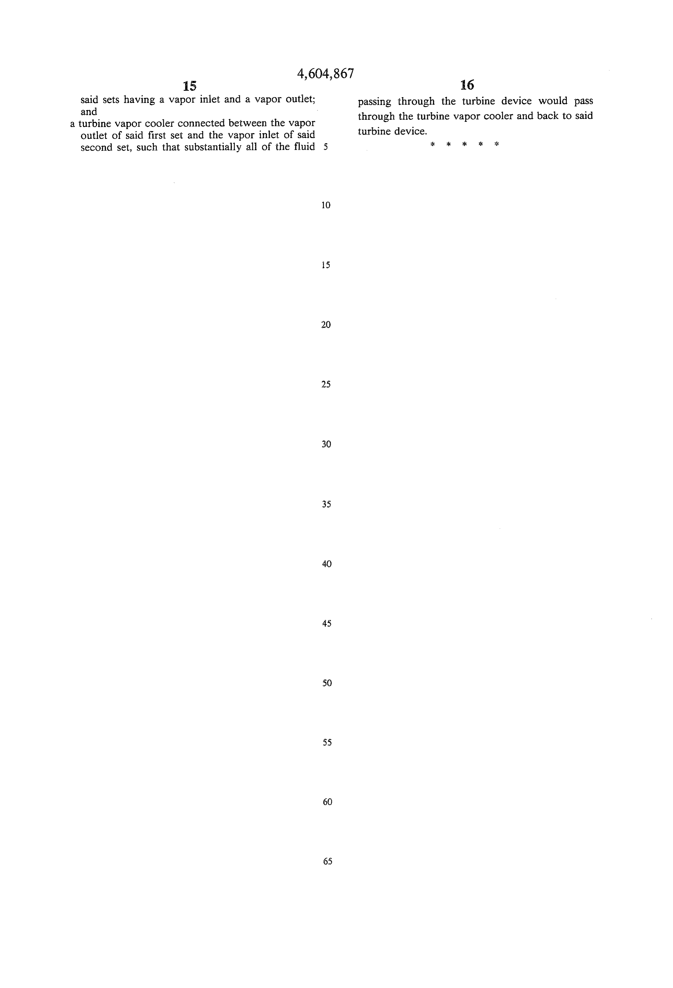
said sets having a vapor inlet and a vapor outlet; passing through the turbine device would pass and vapor cooler connected between the vapor a turbine through the turbine vapor cooler and back to said outlet of said first set and the vapor inlet of said turbine device.
second set, such that substantially all of the fluid 5 & k k is k
Provenance
- Collection
- Cited prior art
- Original PDF
- patentimages.storage.googleapis.com →
- Filed
- 1985-02-26
- Pages
- 12
- Method
- pdftotext (the PDF's own text layer) + pdftoppm 300dpi page scans
- Source
- Google Patents bibliographic record
- Granted
- 1986-08-12
- Inventors
- Alexander I. Kalina
- Transcribed from
- patentimages.storage.googleapis.com →