patent · US5337329
Fluid laser having a roughened, catalytic inner surface
9 August 1994
Page 1 — bibliographic record
United States Patent 19 11 Patent Number: 5,337,329 Foster 45 Date of Patent: Aug. 9, 1994 (54) FLUID LASER HAVING AROUGHENED, OTHER PUBLICATIONS
CATALYTCNNER SURFACE
C. S. Ashley and S. T. Reed, “Sol-Gel Derived AR 76 Inventor: Jack Foster, 856 Renetta Ct, Los Coatings for Solar Receivers', National Technical In Altos, Calif. 94022 formation Service DE 85000192 SAND-84-0662, pp.
21 Appl. No.: 911,679 3-16. (Sep. 1984).
22 Filed: Jul. 7, 1992 Primary Examiner-James W. Davie Attorney, Agent, or Firm-John A. Frazzini 51l Int. Cl................................................ HO3S3/10 57 ABSTRACT 52 U.S.C. ......................................... 372/61; 372/59 58 Field of Search ........................ 372/33, 59, 61, 87 A laser having a roughened, catalytic surface to regen
erate fluid within the lasing chamber that decomposes during operation of the laser. The roughness of this
4,756,000 7/1988 Macken ................................. 372/59 increasing the rate of action of this catalytic surface in 4,873,693 10/1989 Cook, Jr. .............................. 372/33 regenerating fluid. This structure is particularly useful 4,897,848 1/1990 Macken ................................. 372/59 in producing small, handheld CO2 lasers. 4,991,181 2/1991. Upchurch ............................. 372/59 5,148,440 9/1992 Duncan ................................. 372/59 11 Claims, 2 Drawing Sheets
Page 2
Drawing sheet — no readable text.
Page 3
Drawing sheet — no readable text.
Page 4
on Jul. 5, 1988 to John A. Macken, a gold catalyst is
FLUID LASER HAVING AROUGHENED, coated onto the inside surface of the laser chamber wall CATALYTCNNER SURFACE to catalyze reconstitution of the CO2. In order to pre vent this layer of gold from shorting out the discharge
FIELD OF THE INVENTION process, this gold layer is divided into electrically insu This invention relates to lasers in which the lasing lated islands of gold, of length (along the axis of the medium is a fluid within an enclosing wall and relates diameter oflaser cylindrical chamber) preferably less than half the the cylindrical laser chamber. Alterna more particularly to such lasers having within such tively, the gold is deposited as “microscopically divided enclosure a catalyst to facilitate regeneration of decom 10 gold” (i.e., microscopic granules of gold) on the inside posed lasing fluid. Although this invention is applicable surface of the laser chamber wall or the gold is pro to any type of laser having a fluid lasing medium that cessed to form such granules after deposition on the can decompose during operation of the laser, it has particular application to a gas CO2 laser and will be laser oxide chamber wall. Analogous lasers employing a silver catalyst are presented in an associated patent illustrated herein in regard to this particular choice of 15 application entitled Discharge Driven Silver Oxide Cata laser.
lyst With Application To A CO2 Laser.
CONVENTION REGARDING REFERENCE Lasers typically exhibit a peak efficiency (i.e., the NUMERALS ratio of output power to input power) as a function of In the figures, the first digit of a reference numeral 0 input power and therefore are normally operated at indicates the first figure in which is presented the ele are typically input such optimal power. Fabry-Perot type fluid lasers operated in a TEM00 mode, because this ment indicated by that reference numeral. If an element cylindrically symmetric mode of laser light can be well is in more than one figure, the same reference numeral will be used to identify that element in all such figures. focused by conventional optical elements. The main thermal effect in a gas discharge is the transfer of ther
BACKGROUND OF THE INVENTION 25 mal energy from the electrons to translational and rota A significant problem in CO2 lasers is the decomposi tionallaser. energy of the gas that produces the inversion in tion of the CO2 in response to the impact of electrons theFor that are utilized to excite the CO2 molecules, such as by power the that following reasons, lasers typically exhibit a varies linearly with the length of the cylin the following reactions: 30 drical lasing region and is substantially independent of CO2--e-CO--O (1) the diameter of the lasing region. For the electron tem perature profiles of two discharges to be similar, it can
CO2-e-CO-O-le (2) be shown that the power per unit length (i.e., EAOI, where EA is the axial electrical field strength and I is the where 'e' represents an electron in the electrical dis 35 axial current) must be the same for both discharges. The charge through the CO2that excites these gas molecules power of such a laser is therefore proportional to its into excited states from which photons can be emitted length.
as part of the lasing process. Unfortunately, these reac A corresponding similarity law for the diameter D of tions can result in more than 60% of the CO2 within the the cylindrical laser cavity to have optimum electron laser being decomposed. This results in a loss of power 40 energy distribution requires that the product EAOD be and gain and, for small lasers, can even prevent lasing. the same for both discharges. In combination with the Several approaches have been adopted to address this above relation between EA and I, this requires that the problem. In one such class of lasers, a fresh supply of ratio I/D be the same for both discharges. Because of the gas mixture (typically consisting of CO2, N2, He) these relations, the power of a TEM00 mode can be as continuously flows through the laser chamber. How 45 high as for a higher order mode. A typical CO2 laser has ever, because this mixture is approximately 80% he a 9 mm inside bore (i.e. 9 mm inside diameter) and a lium, such lasers exhibit a significant rate of helium length on the order of 1.3 meters and exhibits a power consumption (on the order of 100 liters/hour for a 1000 of approximately 40 Watts/m times the length of the Watt laser), which is not only costly, but a wasteful use lasing region.
of a limited resource. The helium is included, because its 50 In certain applications in medicine, such as removing small atomic mass and inert chemical activity make it freckles, it would be advantageous to have a handheld ideal for conducting heat away from the region within laser that can be comfortably held by a technician and which the CO2 is induced to lase (i.e., the "lasing re can produce a beam of approximately 5-10 Watts. Un gion'). fortunately, a conventional 10 Watt CO2 laser exhibit In a second class of CO2 lasers, this gas is pumped ing a typical 20% efficiency is approximately 25 cm past aheated catalyst, such as platinum, located external long. For convenience of use, such a laser should have to the laser chamber to regenerate the CO2. Unfortu a length on the order of the length of a person's palm nately, in such lasers, about 10% of the gas must still be (on the order of 12 cm). Therefore, it would be very dumped in each cycle. In a third class of CO2 lasers, useful to produce a CO2 laser exhibiting at least twice attempts have been made to include such a heated cata the output power per unit length of conventional CO2 lyst within the laser chamber. However, such heated lasers.
catalysts increase the gas temperature to a level that SUMMARY OF THE INVENTION prevents lasing. In a fourth class of CO2 lasers, the laser gas is passed through an ambient temperature granular In accordance with the illustrated preferred embodi catalyst (such as platinum on tin oxide, Hopcalite or ment, a fluid laser is presented that exhibits about a cobalt oxide) located outside of the laser chamber. two-fold increase in output power per unit length com In U.S. Pat. No. 4,756,000 entitled Discharge Driven pared to analogous conventional fluid lasers. On a sur Gold Catalyst With Application To A CO2 Laser, issued face within the laser chamber, a catalytic coating is
Page 5
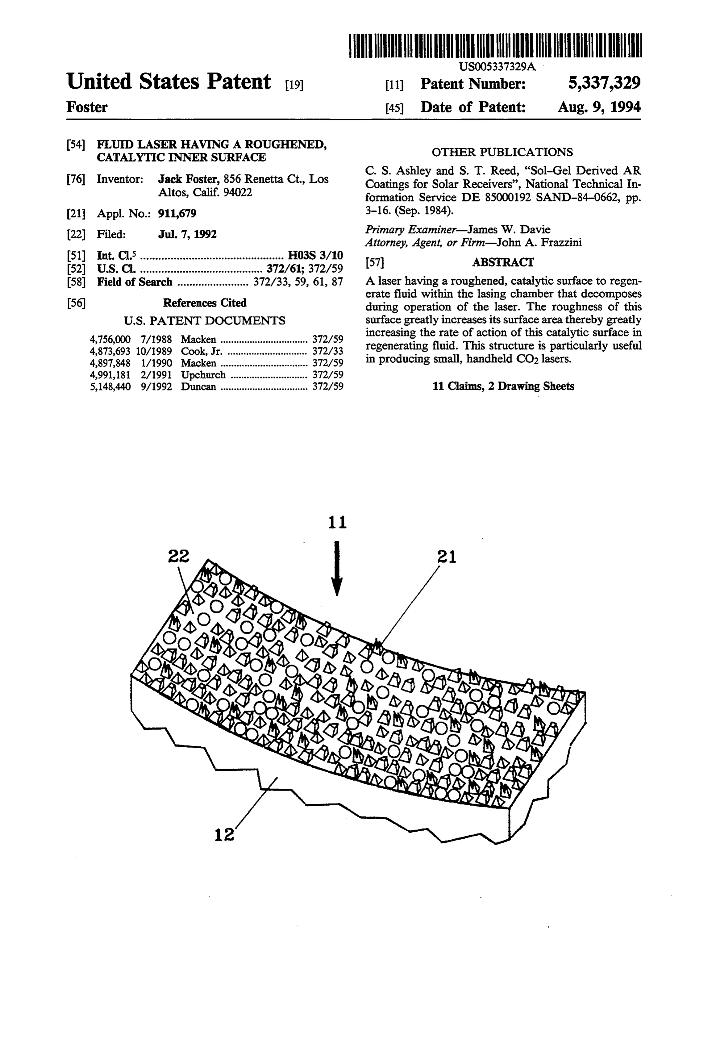
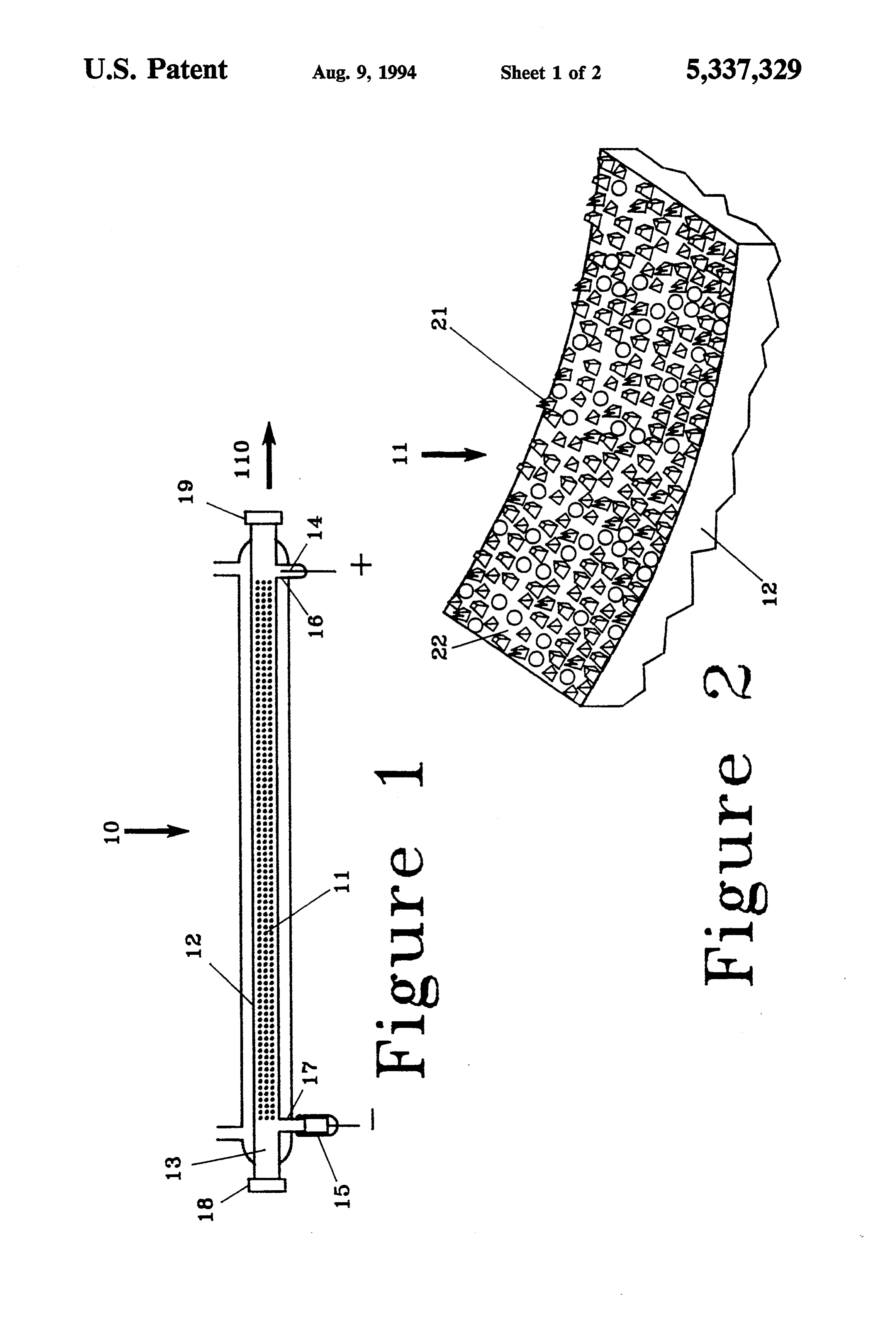
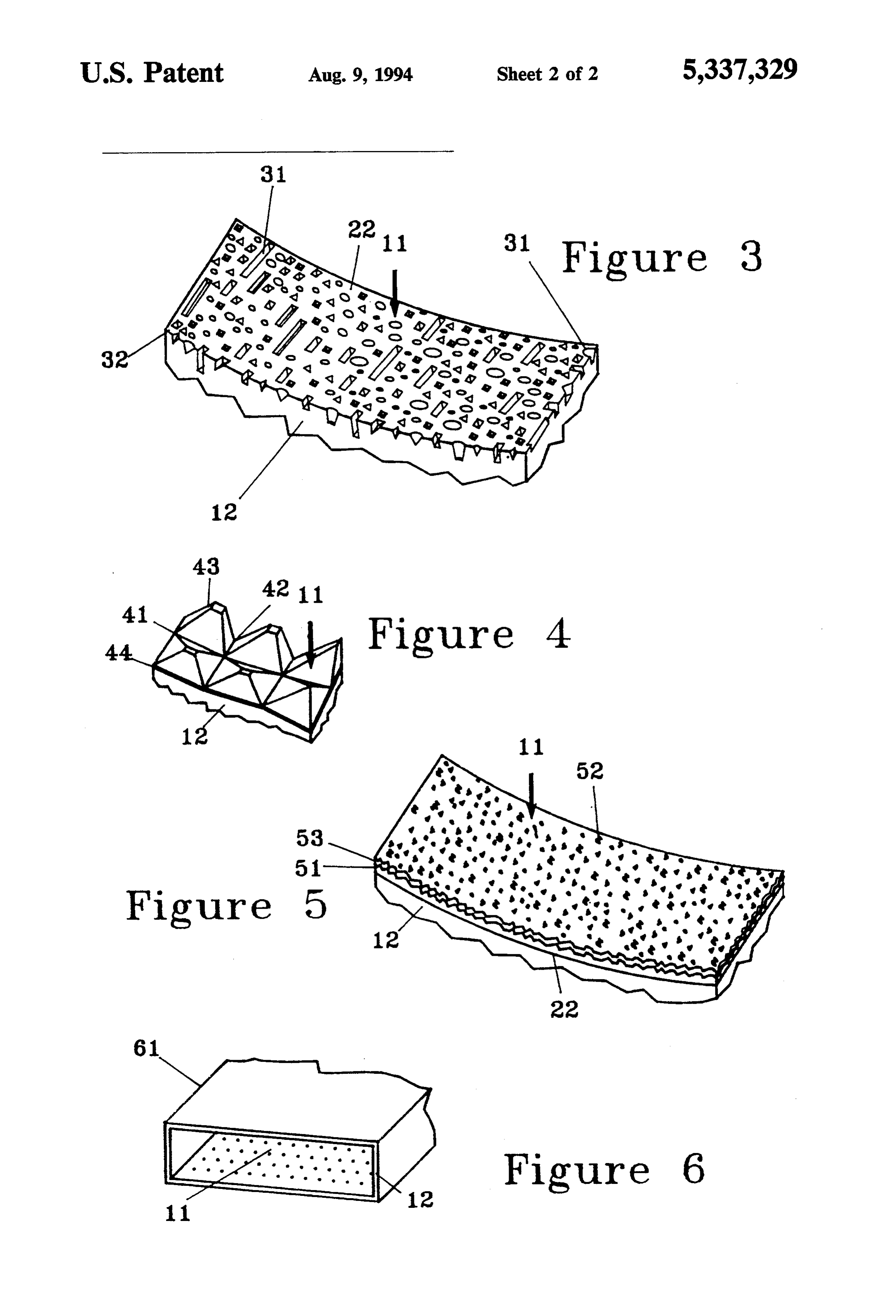
produced that exhibits a toughened surface texture. FIG. 4 is a perspective view of a portion of a rough Such a roughened surface exhibits a much larger sur ened, catalytic inner surface that has been roughed by face per unit length of the laser than does a smooth cutting or scratching at least a pair of spiral, approxi surface, thereby providing a comparably greater rate of mately v-shaped grooves to produce approximately catalytic regeneration of the lasing fluid. 5 pyramidal regions of this surface. By a "smooth' inner surface is meant a surface area FIG. 5 is a lateral, cross-sectional view of the inner that is no more than 1.3 times its surface area if it were surface of a laser chamber sidewall that has been rough a perfectly smooth material. By a "roughened surface” ened by production on this inner surface of a coating, is meant a surface that has an area at least 1.3 times the such as activated charcoal coating or a solgel, having a surface area of a perfectly smooth surface having the 10 large surface area-to-volume ratio. same macroscopic shape. By "macroscopic shape' is FIG. 6 is a perspective cross-sectional view of a por meant the shape of the surface over dimensions compa tion of a waveguide slab laser having a toughened, rable to the lateral or longitudinal dimensions of the catalytic inner surface.
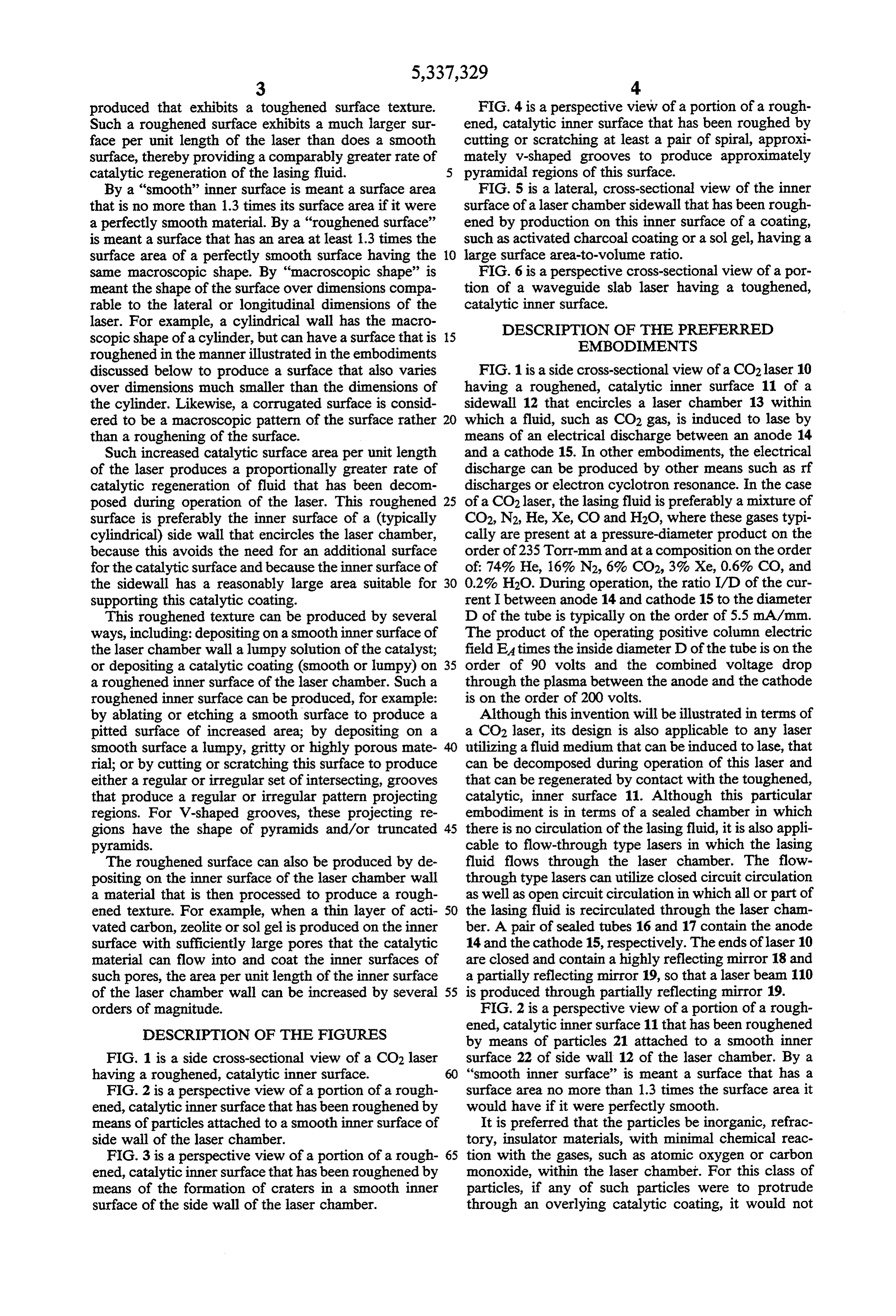
laser. For example, a cylindrical wall has the macro DESCRIPTION OF THE PREFERRED scopic shape of a cylinder, but can have a surface that is 15 EMBODIMENTS roughened in the manner illustrated in the embodiments discussed below to produce a surface that also varies FIG. 1 is a side cross-sectional view of a CO2 laser 10 over dimensions much smaller than the dimensions of having a roughened, catalytic inner surface 11 of a the cylinder. Likewise, a corrugated surface is consid sidewall 12 that encircles a laser chamber 13 within ered to be a macroscopic pattern of the surface rather 20 which a fluid, such as CO2 gas, is induced to lase by than a roughening of the surface. means of an electrical discharge between an anode 14 Such increased catalytic surface area per unit length and a cathode 15. In other embodiments, the electrical of the laser produces a proportionally greater rate of discharge can be produced by other means such as rf catalytic regeneration of fluid that has been decom discharges or electron cyclotron resonance. In the case posed during operation of the laser. This roughened 25 of a CO2 laser, the lasing fluid is preferably a mixture of surface is preferably the inner surface of a (typically CO2, N2, He, Xe, CO and H2O, where these gases typi cylindrical) side wall that encircles the laser chamber, cally are present at a pressure-diameter product on the because this avoids the need for an additional surface order of 235 Torr-mm and at a composition on the order for the catalytic surface and because the inner surface of of: 74%. He, 16% N2, 6% CO2, 3% Xe, 0.6% CO, and the sidewall has a reasonably large area suitable for 30 0.2% H2O. During operation, the ratio I/D of the cur supporting this catalytic coating. rent I between anode 14 and cathode 15 to the diameter This roughened texture can be produced by several D of the tube is typically on the order of 5.5 mA/mm. ways, including: depositing on a smoothinner surface of The product of the operating positive column electric the laser chamber wall a lumpy solution of the catalyst; field E4 times the inside diameter D of the tube is on the or depositing a catalytic coating (smooth or lumpy) on 35 order of 90 volts and the combined voltage drop a roughened inner surface of the laser chamber. Such a through the plasma between the anode and the cathode roughened inner surface can be produced, for example: is on the order of 200 volts.
by ablating or etching a smooth surface to produce a Although this invention will be illustrated in terms of pitted surface of increased area; by depositing on a a CO2 laser, its design is also applicable to any laser smooth surface a lumpy, gritty or highly porous mate utilizing a fluid medium that can be induced to lase, that rial; or by cutting or scratching this surface to produce can be decomposed during operation of this laser and either a regular or irregular set of intersecting, grooves that can be regenerated by contact with the toughened, that produce a regular or irregular pattern projecting catalytic, inner surface 11. Although this particular regions. For V-shaped grooves, these projecting re embodiment is in terms of a sealed chamber in which gions have the shape of pyramids and/or truncated 45 there is no circulation of the lasing fluid, it is also appli pyramids. cable to flow-through type lasers in which the lasing The roughened surface can also be produced by de fluid flows through the laser chamber. The flow positing on the inner surface of the laser chamber wall through type lasers can utilize closed circuit circulation a material that is then processed to produce a rough as well as open circuit circulation in which all or part of ened texture. For example, when a thin layer of acti 50 the lasing fluid is recirculated through the laser chan vated carbon, zeolite or sol gel is produced on the inner ber. A pair of sealed tubes 16 and 17 contain the anode surface with sufficiently large pores that the catalytic 14 and the cathode 15, respectively. The ends of laser 10 material can flow into and coat the inner surfaces of are closed and contain a highly reflecting mirror 18 and such pores, the area per unit length of the inner surface a partially reflecting mirror 19, so that a laser beam 110 of the laser chamber wall can be increased by several 55 is produced through partially reflecting mirror 19. orders of magnitude. FIG. 2 is a perspective view of a portion of a rough
DESCRIPTION OF THE FIGURES
ened, catalytic inner surface 11 that has been roughened by means of particles 21 attached to a smooth inner
FIG. 1 is a side cross-sectional view of a CO2 laser surface 22 of side wall 12 of the laser chamber. By a having a roughened, catalytic inner surface. 60 “smooth inner surface' is meant a surface that has a FIG. 2 is a perspective view of a portion of a rough surface area no more than 1.3 times the surface area it ened, catalytic inner surface that has been roughened by would have if it were perfectly smooth. means of particles attached to a smooth inner surface of It is preferred that the particles be inorganic, refrac side wall of the laser chamber. tory, insulator materials, with minimal chemical reac FIG. 3 is a perspective view of a portion of a rough- 65 tion with the gases, such as atomic oxygen or carbon ened, catalytic inner surface that has been roughened by monoxide, within the laser chamber. For this class of means of the formation of craters in a smooth inner particles, if any of such particles were to protrude surface of the side wall of the laser chamber. through an overlying catalytic coating, it would not
Page 6
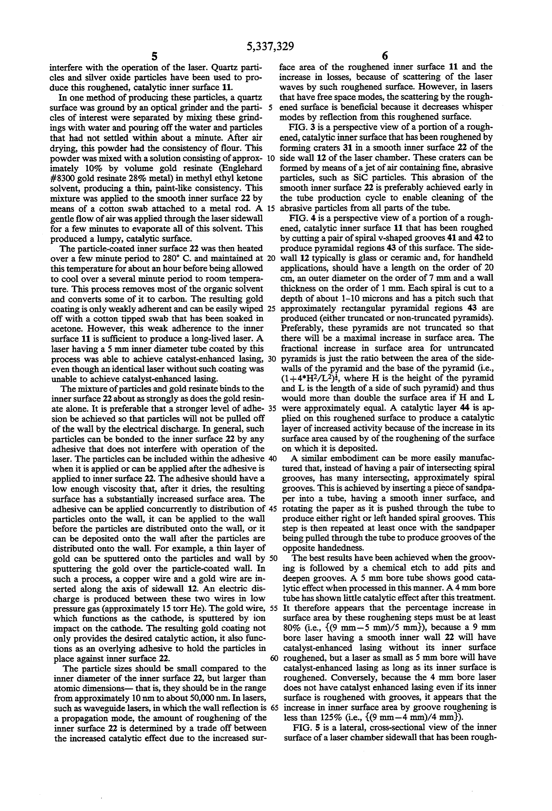
interfere with the operation of the laser. Quartz parti face area of the roughened inner surface 11 and the cles and silver oxide particles have been used to pro increase in losses, because of scattering of the laser duce this roughened, catalytic inner surface 11. waves by such roughened surface. However, in lasers In one method of producing these particles, a quartz that have free space modes, the scattering by the rough surface was ground by an optical grinder and the parti ened surface is beneficial because it decreases whisper cles of interest were separated by mixing these grind modes by reflection from this roughened surface. ings with water and pouring off the water and particles FIG. 3 is a perspective view of a portion of a rough that had not settled within about a minute. After air ened, catalytic inner surface that has been roughened by drying, this powder had the consistency of flour. This forming craters 31 in a smooth inner surface 22 of the powder was mixed with a solution consisting of approx 10 side wall 12 of the laser chamber. These craters can be imately 10% by volume gold resinate (Englehard formed by means of a jet of air containing fine, abrasive #8300 gold resinate 28% metal) in methyl ethyl ketone particles, such as SiC particles. This abrasion of the solvent, producing a thin, paint-like consistency. This smooth inner surface 22 is preferably achieved early in mixture was applied to the smooth inner surface 22 by the tube production cycle to enable cleaning of the means of a cotton Swab attached to a metal rod. A 15 abrasive particles from all parts of the tube. gentle flow of air was applied through the laser sidewall FIG. 4 is a perspective view of a portion of a rough for a few minutes to evaporate all of this solvent. This ened, catalytic inner surface 11 that has been roughed produced a lumpy, catalytic surface. by cutting a pair of spiral v-shaped grooves 41 and 42 to The particle-coated inner surface 22 was then heated produce pyramidal regions 43 of this surface. The side over a few minute period to 280 C. and maintained at 20 wall 12 typically is glass or ceramic and, for handheld this temperature for about an hour before being allowed applications, should have a length on the order of 20 to cool over a several minute period to room tempera cm, an outer diameter on the order of 7 mm and a wall ture. This process removes most of the organic solvent thickness on the order of 1 mm. Each spiral is cut to a and converts some of it to carbon. The resulting gold depth of about 1-10 microns and has a pitch such that coating is only weakly adherent and can be easily wiped 25 approximately rectangular pyramidal regions 43 are off with a cotton tipped swab that has been soaked in produced (either truncated or non-truncated pyramids). acetone. However, this weak adherence to the inner Preferably, these pyramids are not truncated so that surface 11 is sufficient to produce a long-lived laser. A there will be a maximal increase in surface area. The laser having a 5 mm inner diameter tube coated by this fractional increase in surface area for untruncated process was able to achieve catalyst-enhanced lasing, 30 pyramids is just the ratio between the area of the side even though an identical laser without such coating was walls of the pyramid and the base of the pyramid (i.e., unable to achieve catalyst-enhanced lasing. (1-4*H2/L2), where H is the height of the pyramid The mixture of particles and gold resinate binds to the and L is the length of a side of such pyramid) and thus inner surface 22 about as strongly as does the gold resin would more than double the surface area if H and L ate alone. It is preferable that a stronger level of adhe 35 were approximately equal. A catalytic layer 44 is ap sion be achieved so that particles will not be pulled off plied on this roughened surface to produce a catalytic of the wall by the electrical discharge. In general, such layer of increased activity because of the increase in its particles can be bonded to the inner surface 22 by any surface area caused by of the roughening of the surface adhesive that does not interfere with operation of the on which it is deposited.
laser. The particles can be included within the adhesive 40 A similar embodiment can be more easily manufac when it is applied or can be applied after the adhesive is tured that, instead of having a pair of intersecting spiral applied to inner surface 22. The adhesive should have a grooves, has many intersecting, approximately spiral low enough viscosity that, after it dries, the resulting grooves. This is achieved by inserting a piece of sandpa surface has a substantially increased surface area. The per into a tube, having a smooth inner surface, and adhesive can be applied concurrently to distribution of 45 rotating the paper as it is pushed through the tube to particles onto the wall, it can be applied to the wall produce either right or left handed spiral grooves. This before the particles are distributed onto the wall, or it step is then repeated at least once with the sandpaper can be deposited onto the wall after the particles are being pulled through the tube to produce grooves of the distributed onto the wall. For example, a thin layer of opposite handedness.
gold can be sputtered onto the particles and wall by 50 The best results have been achieved when the groov sputtering the gold over the particle-coated wall. In ing is followed by a chemical etch to add pits and such a process, a copper wire and a gold wire are in deepen grooves. A 5 mm bore tube shows good cata serted along the axis of sidewall 12. An electric dis lytic effect when processed in this manner. A 4mm bore charge is produced between these two wires in low tube has shown little catalytic effect after this treatment. pressure gas (approximately 15 torr He). The gold wire, 55 It therefore appears that the percentage increase in which functions as the cathode, is sputtered by ion surface area by these roughening steps must be at least impact on the cathode. The resulting gold coating not 80% (i.e., {(9 mm-5 mm)/5 mm), because a 9 mm only provides the desired catalytic action, it also func bore laser having a smooth inner wall 22 will have tions as an overlying adhesive to hold the particles in catalyst-enhanced lasing without its inner surface place against inner surface 22. roughened, but a laser as small as 5 mm bore will have The particle sizes should be small compared to the catalyst-enhanced lasing as long as its inner surface is inner diameter of the inner surface 22, but larger than roughened. Conversely, because the 4 mm bore laser atomic dimensions- that is, they should be in the range does not have catalyst enhanced lasing even if its inner from approximately 10 nm to about 50,000 nm. In lasers, surface is roughened with grooves, it appears that the such as waveguide lasers, in which the wall reflection is 65 increase in inner surface area by groove roughening is a propagation mode, the amount of roughening of the less than 125% (i.e., {(9 mm-4 mm)/4 mm). inner surface 22 is determined by a trade off between FIG. 5 is a lateral, cross-sectional view of the inner the increased catalytic effect due to the increased sur surface of a laser chamber sidewall that has been rough
Page 7
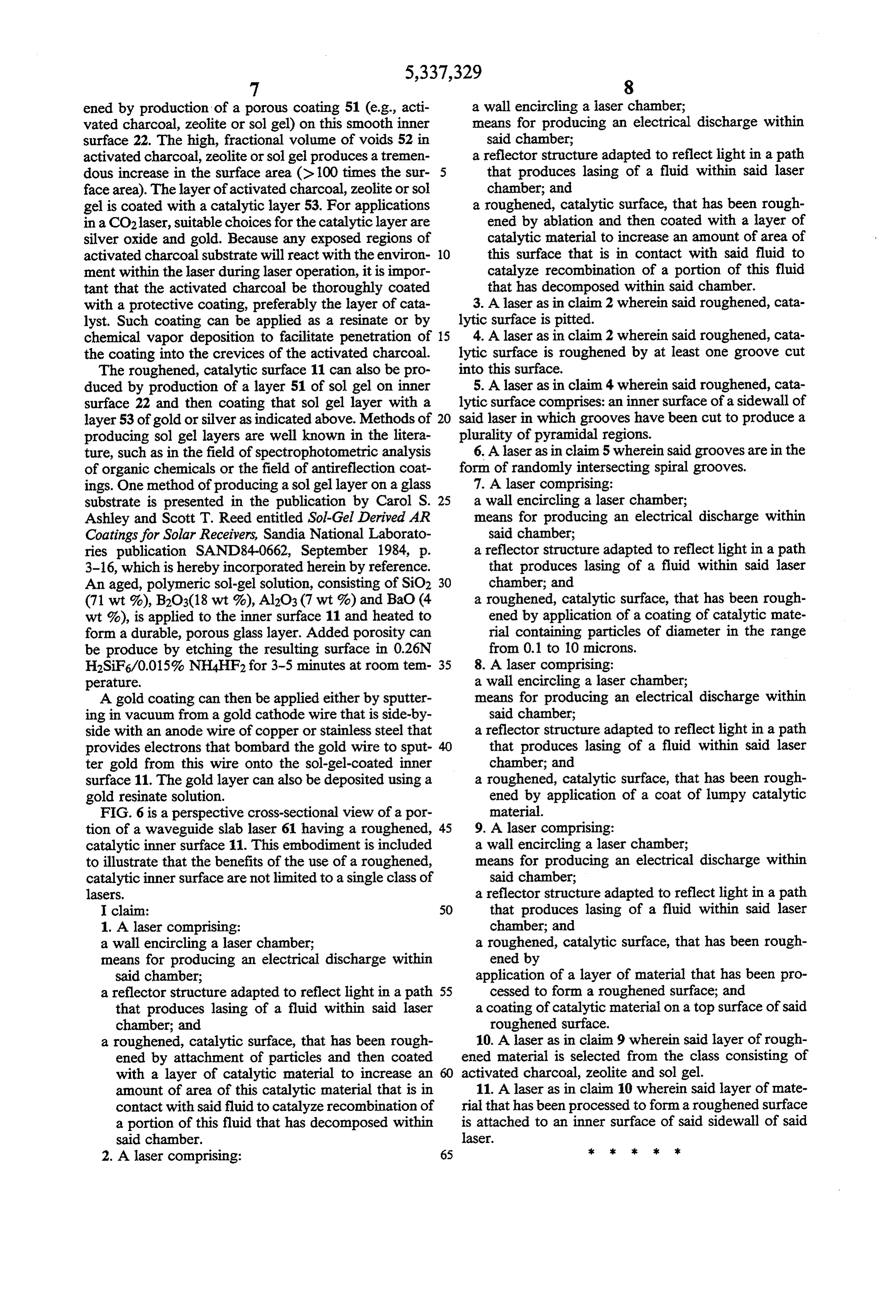
ened by production of a porous coating 51 (e.g., acti a wall encircling a laser chamber; vated charcoal, zeolite or sol gel) on this smooth inner means for producing an electrical discharge within surface 22. The high, fractional volume of voids 52 in said chamber;
activated charcoal, zeolite or solgel produces a tremen a reflector structure adapted to reflect light in a path dous increase in the surface area (> 100 times the sur- 5 that produces lasing of a fluid within said laser face area). The layer of activated charcoal, zeolite or sol chamber; and gel is coated with a catalytic layer 53. For applications a roughened, catalytic surface, that has been rough in a CO2 laser, suitable choices for the catalytic layer are ened by ablation and then coated with a layer of silver oxide and gold. Because any exposed regions of catalytic material to increase an amount of area of activated charcoal substrate will react with the environ- 10 this surface that is in contact with said fluid to ment within the laser during laser operation, it is impor catalyze recombination of a portion of this fluid tant that the activated charcoal be thoroughly coated that has decomposed within said chamber. with a protective coating, preferably the layer of cata 3. A laser as in claim 2 wherein said roughened, cata lyst. Such coating can be applied as a resinate or by lytic surface is pitted.
chemical vapor deposition to facilitate penetration of 15 4. A laser as in claim 2 wherein said roughened, cata the coating into the crevices of the activated charcoal. lytic surface is roughened by at least one groove cut The roughened, catalytic surface 11 can also be pro into this surface.
duced by production of a layer 51 of sol gel on inner 5. A laser as in claim 4 wherein said roughened, cata surface 22 and then coating that sol gel layer with a lytic surface comprises: an inner surface of a sidewall of layer 53 of gold or silver as indicated above. Methods of 20 said laser in which grooves have been cut to produce a producing sol gel layers are well known in the litera plurality of pyramidal regions.
ture, such as in the field of spectrophotometric analysis 6. A laser as in claim 5 wherein said grooves are in the of organic chemicals or the field of antireflection coat form of randomly intersecting spiral grooves. ings. One method of producing a solgel layer on a glass 7. A laser comprising:
substrate is presented in the publication by Carol S. 25 a wall encircling a laser chamber;
Ashley and Scott T. Reed entitled Sol-Gel Derived AR means for producing an electrical discharge within Coatings for Solar Receivers, Sandia National Laborato said chamber;
ries publication SAND84-0662, September 1984, p. a reflector structure adapted to reflect light in a path 3-16, which is hereby incorporated herein by reference. that produces lasing of a fluid within said laser An aged, polymeric sol-gel solution, consisting of SiO2 30 chamber; and (71 wt %), B2O3(18 wt %), Al2O3 (7 wt %) and BaO (4 a roughened, catalytic surface, that has been rough wt %), is applied to the inner surface 11 and heated to ened by application of a coating of catalytic mate form a durable, porous glass layer. Added porosity can rial containing particles of diameter in the range be produce by etching the resulting surface in 0.26N from 0.1 to 10 microns.
H2SiF6/0.015% NH4HF2 for 3-5 minutes at room tem- 35 8. A laser comprising:
perature. a wall encircling a laser chamber; A gold coating can then be applied either by sputter means for producing an electrical discharge within ing in vacuum from a gold cathode wire that is side-by said chamber;
side with an anode wire of copper or stainless steel that a reflector structure adapted to reflect light in a path provides electrons that bombard the gold wire to sput- 40 that produces lasing of a fluid within said laser ter gold from this wire onto the sol-gel-coated inner chamber; and surface 11. The gold layer can also be deposited using a a roughened, catalytic surface, that has been rough gold resinate solution. ened by application of a coat of lumpy catalytic FIG. 6 is a perspective cross-sectional view of a por material.
tion of a waveguide slab laser 61 having a roughened, 45 9. A laser comprising:
catalytic inner surface 11. This embodiment is included a wall encircling a laser chamber; to illustrate that the benefits of the use of a roughened, means for producing an electrical discharge within catalytic inner surface are not limited to a single class of said chamber;
lasers. a reflector structure adapted to reflect light in a path I claim: 50 that produces lasing of a fluid within said laser 1. A laser comprising: chamber; and a wall encircling a laser chamber; a roughened, catalytic surface, that has been rough means for producing an electrical discharge within ened by said chamber; application of a layer of material that has been pro a reflector structure adapted to reflect light in a path 55 cessed to form a roughened surface; and that produces lasing of a fluid within said laser a coating of catalytic material on a top surface of said chamber; and roughened surface.
a roughened, catalytic surface, that has been rough 10. A laser as in claim 9 wherein said layer of rough ened by attachment of particles and then coated ened material is selected from the class consisting of with a layer of catalytic material to increase an 60 activated charcoal, zeolite and sol gel. amount of area of this catalytic material that is in 11. A laser as in claim 10 wherein said layer of mate contact with said fluid to catalyze recombination of rial that has been processed to form a roughened surface a portion of this fluid that has decomposed within is attached to an inner surface of said sidewall of said said chamber. laser.
Provenance
- Collection
- Cited prior art
- Original PDF
- patentimages.storage.googleapis.com →
- Filed
- 1992-07-07
- Pages
- 7
- Method
- pdftotext (the PDF's own text layer) + pdftoppm 300dpi page scans
- Source
- Google Patents bibliographic record
- Granted
- 1994-08-09
- Inventors
- Jack Foster; UNIVERSAL LASER CORP
- Transcribed from
- patentimages.storage.googleapis.com →