patent · US4756000
Discharge driven gold catalyst with application to a CO2 laser
5 July 1988
Page 1 — bibliographic record
United States Patent (19) 11 Patent Number: 4,756,000 Macken 45 Date of Patent: Jul. 5, 1988 54 DISCHARGE DRIVEN GOLD CATALYST FOREIGN PATENT DOCUMENTS
WITH APPLICATION TO A CO2 LASER
76 Inventor: John A. Macken, 3755 Wallace Rd., 2083944 3/1982 United Kingdom .................. 372/59 Santa Rosa, Calif. 95404 2028571 3/1986 United Kingdom .................. 372/59 (21) Appl. No.: 16,061 Primary Examiner-Léon Scott, Jr. Attorney, Agent, or Firm-Edward E. Roberts (22 Filed: Feb. 18, 1987 57 ABSTRACT 51) Int. Cl* ................................................ H01S 3/22 A device and process using a gold as a catalyst for 52 U.S. Cl. ........ 372/59; 372/98; oxidizing carbon monoxide to form CO2 at ambient 372/92 temperatures. This has particular application to CO2 58) Field of Search ....................... 372/59, 87, 83, 89, lasers. In one CO2 laser embodiment, gold is distributed 372/55, 61,92, 34; 378/98, 58, 81 on the walls of the discharge volume. The gold is di 56 References Cited vided to form electrically isolated islands to prevent interference with the discharge. Energetic forms of
4,617,668 10/1986 Rudko et al. ......................... 372/59 gold catalyst. In another embodiment, the gold catalyst 4,639,926 1/1987 Wana et al. ... ... 372/56 is used in a convective flow laser. 4,641,313 2/1987 Tobin et al. ... ... 378/56 4,651,324 3/1987 Prein et al. ........................ ... 372/59 11 Claims, 2 Drawing Sheets
Page 2
/O ENVELOPE CONTAINING:
A) GAS INCLUDING CO2
8) AMPLIFICATION VOLUME
C) DSCHARGE
D) GOLD SURFACE
TRANSPORT
O2 FORMED
ETC. FORMED
GOLD SURFACE
CO2 FORMED
CO2 TRANSPORT
Page 3
Drawing sheet — no readable text.
Page 4
the gas must be dumped with each cycle and new gas
DSCHARGE DRIVEN GOLD CATALYST WITH added. Therefore, presently, a 1000 watt CO2 laser APPLICATION TO A CO2 LASER equipped with a platinum recycler typically consumes
BACKGROUND OF THE INVENTION
about 10 liters of laser gas per hour.
5 This problem can be placed in greater perspective
The background of the invention will be discussed in when it is realized that presently there have been about two parts: 10,000 CO2 lasers sold worldwide. While some of these 1. Field of the Invention are sealed off, the majority are consuming a vast amount This invention relates to both catalysts and lasers. 10 of helium which is not only expensive, but depleting a More particularly, it relates to a method and apparatus natural resource which has a limited supply. The sealed for improving CO2 lasers by catalytically reforming off CO2 lasers do not consume helium, but pay a differ CO2 which was decomposed by the electrical dis ent kind of penalty since they usually run at an output charge. power which is considerably reduced compared to a 2. Description of the Prior Art comparable size flowing CO2 laser. Since the CO2 laser was invented, an undesirable 15 This problem has received a great deal of attention. characteristic of this laser has been the fact that the The following articles and patents are cited as prior art electrical discharge needed to excite the laser gas also references:
causes the CO2 in the discharge to disassociate accord 1. P. D. Tannen et al "Species Composition in the ing to one of the following two reactions: CO2 Discharge Laser' IEEE Journal of Quantum
CO2--e-CO-O Electronics Vol QE10, No. 1 1974;
2. C. Willis "Catalytic Control of the Gas Chemistry
CO2+-e-CO-O--e of Sealed TEA CO2 Lasers' J. Appl. Phys. 50 (4)
where "e" represents an electron in the discharge. 25 3. D. S. Stark "A Sealed 100 Hz CO2 TEA Laser This reaction eventually reaches an equilibrium ac Using High CO2 Concentrations and Ambient cording to the reaction: Temperature Catalysts' J. Phys. E.: Sci. Instrum.
Circulation System';
However, this equilibrium usually is not reached until 30 5. U.S. Pat. No. 3,569,857.J. A. Macken "Method and more than 60% of the CO2 is decomposed. The problem Means for Achieving Chemical Equilibrium in a is that the decomposition products of CO and O2 have a Sealed Off CO2 Laser; and partial poisoning effect on the laser. The result is char 6. A. B. Lamb et al "The Removal of Carbon Monox acterized by a loss of power, a loss of gain, and a desta 35 ide from Air" J. of Industrial and Eng. Chem. bilization of the electric discharge. March 1920.
In higher power lasers, this damaging effect is dealt In addition to the use of external catalyst, there has with by continuously flowing the gas (a mixture of CO2, also been some attempt to place the catalyst inside the N2 and He with helium making up about 80% of the laser by using a heated platinum wire inside the laser or total) through a discharge in a time short enough to using permit only partial decomposition of the CO2. The rate However, this cathode a heated which shows catalytic activity.
has been unsuccessful in significantly of decomposition depends on many factors such as cur reversing the breakdown rent density and gas pressure, but, in general, it can be too slow to carry the gasoftoCO2 because gas diffusion is a small area of the tube said that the decomposition rate is quite rapid, usually containing the heated platinum wire or the heated cath with a time constant between 0.01 second and 10 sec onds. 45 ode. It is not possible to coat large portions of the laser This reaction was first identified and characterized by discharge would be cavity with heated platinum. While this successful in reconstituting the decomposed the applicant herein in 1967. Since that time, there have been many studies of this process in an attempt to mini gas, the CO2 laser would stop lasing because the large mize the gas consumption expense and nuisance associ area to heated platinum would also raise the gas tempera ated with high power CO2 lasers. At lower power lev 50 tureCatalysts an unacceptable level for laser action. which work at ambient temperature for the els, (less than 60 watts) sealed off CO2 lasers have been CO-O2 reaction are also very slow compared to constructed and used wherein the loss in power associ heated platinum. These ambient temperature catalysts ated with the partial breakdown of the CO2 in the elec trical discharge has been accepted. include platinum on tin oxide (Ref. #3), Hopcalite (Ref. If a CO2 laser merely flows the gas through the laser 55 #6-50% MnO2, 30% AuC, 15% CO2O3 and 5% Ag2O) once and expels the gas, it can consume a substantial and Cobalt oxide (Ref. #6). To use these catalysts at quantity of helium. For example, a 1000 watt CO2 laser ambient temperature, it is necessary to offset the slow with no recycling of gas can consume about 100 liters of reaction rates by providing intimate contact between laser gas (mostly helium) at standard pressure and tem the gas and the catalyst. This is usually done by flowing perature in one hour. Fortunately, it has been found 60 the gas through a granular form of the catalyst. possible to reconvert the CO and O2 to CO2 through the This requires placing the catalyst away from the laser use of a platinum catalyst heated to about 330 C. To do amplification volume. A pump is used to circulate the this, a vacuum pump is used to continuously circulate gas through the catalyst. Tests indicate that these above the gas through a closed loop which includes the elec mentioned ambient temperature catalysts cannot be trical discharge section of the laser, the heated catalyst 65 used inside the laser on the walls of the discharge vol and the vacuum pump. Unfortunately, this process is ume for various reasons, such as slow reaction rates, not only expensive in terms of equipment and complex destabilization of the discharge and chemical decompo ity, but it is also still wasteful of gas, since about 10% of sition of the catalyst.
Page 5
In contrast to the prior art, this invention teaches a energy by providing intermediate reactions. However, way of reconstituting the decomposed CO2 inside the it has been realized by applicant that inside the CO2 electrical discharge cavity of a CO2 laser. This can be laser, there is a unique environment which offers a new done at ambient temperature, without destabilizing the approach to catalysts.
discharge and without the need to recirculate the gas. It Inside the CO2 laser, the electric discharge makes is also possible to use the teachings of this invention to energetic species of oxygen compared to O2. This ener reconstitute the decomposed CO2 in a "flow' laser. In this case, the low operating temperature of this process getic oxygen usually cannot combine with CO (without a third body) because there is apparently too much en does not require the use of additional heating of the gas ergy available. It is no longer a problem of overcoming as would be required in a platinum catalyst. These and 10 the activation energy, but in the gaseous phase, the other advantages will be presented. The teachings of problem this invention are also applicable to other devices in can hold istogether. removing energy so that the CO2 molecule For example, the very process of addition to lasers. decomposing CO2 yields atomic oxygen (O) according
to the equation:
In a CO2 laser, the electrical discharge has an undesir CO2--e-CO-O--e able side effect of decomposing the CO2 to carbon mon oxide and oxygen. However, the electric discharge also Atomic oxygen can also be formed inside the dis makes short lived, energetic forms of oxygen which are charge in several ways, including the following: very reactive. This invention describes a catalyst which 20 only works in the presence of these short lived ener getic forms of oxygen.
In one embodiment of the invention, finely divided The atomic oxygen often lasts until it diffuses to the gold coats the walls facing the laser amplification vol wall. Some of the atomic oxygen also combines with ume. At ambient temperature, the CO and energetic 25 O2 to form Ozone O3 but this reaction also needs a third forms of oxygen (such as atomic oxygen) can rapidly body. Ozone is also very reactive.
react on the gold surface. Finally, diatomic oxygen (O2) is known to have at In diffusion limited lasers, the gold catalyst should be least two long lived excited vibrational states which "broadly distributed on the walls facing the discharge. will be designated as O2 and O2**. Therefore, even The gold is divided sufficiently to prevent deviating the 30 molecular oxygen (O2) is being continuously excited to electrical discharge. an energetic species as long as it remains in the dis In another embodiment applicable to convective flow charge. Therefore, in the discharge, there exists at least lasers, the gold catalyst is positioned in the flowing gas four forms of energetic oxygen which are electrically near the exhaust end of the laser discharge. Besides neutral. None of these would normally be encountered lasers, this invention has application to other environ 35 either in air or in the laser gas once the gas has left the ments which-generate energetic forms of oxygen. discharge region for a time longer than the life time of BRIEF DESCRIPTION OF THE DRAWINGS the various species of energetic oxygen. In summary, these four neutral energetic oxygen states and their
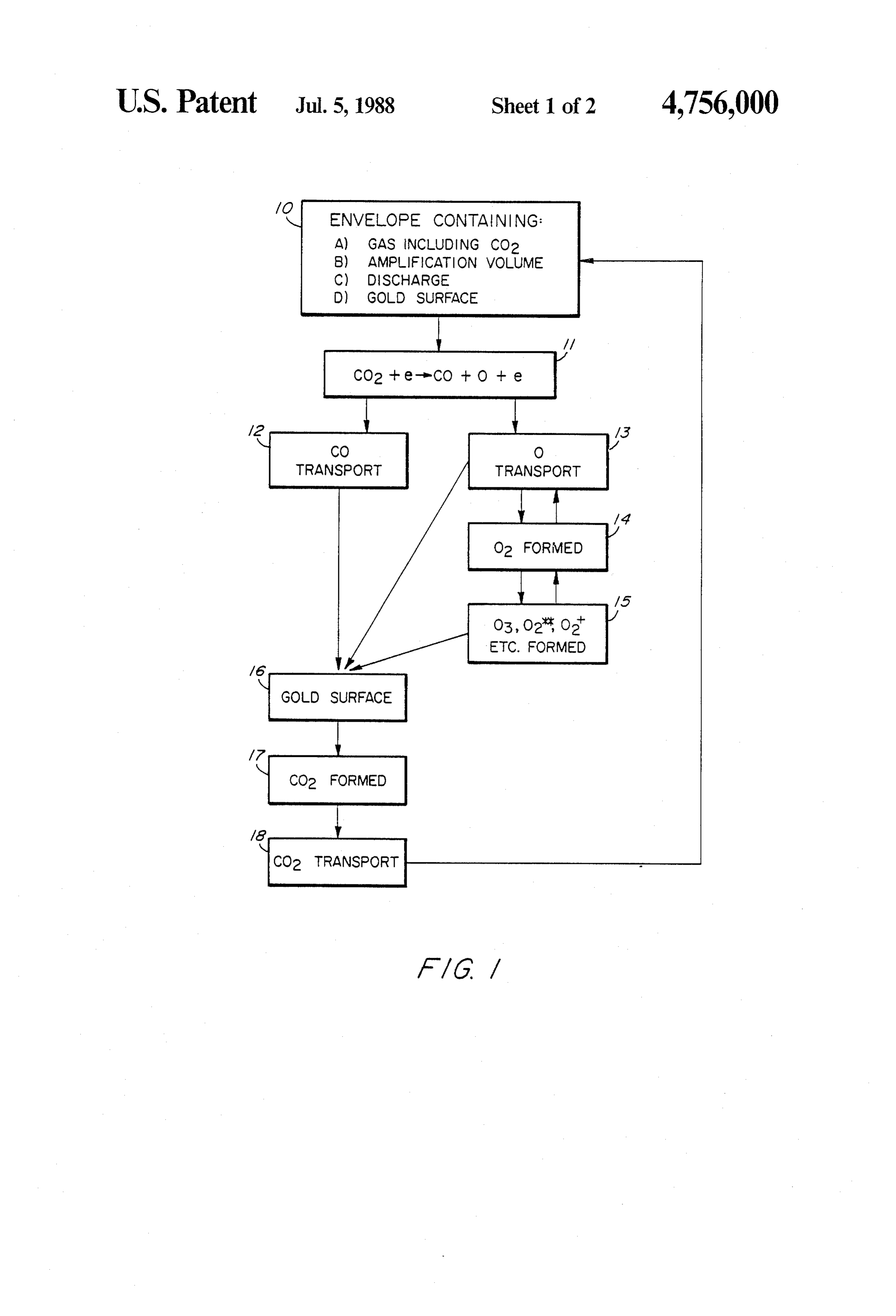
FIG. 1 is a flow diagram showing the chemical and energies of formation relative to O2 are:
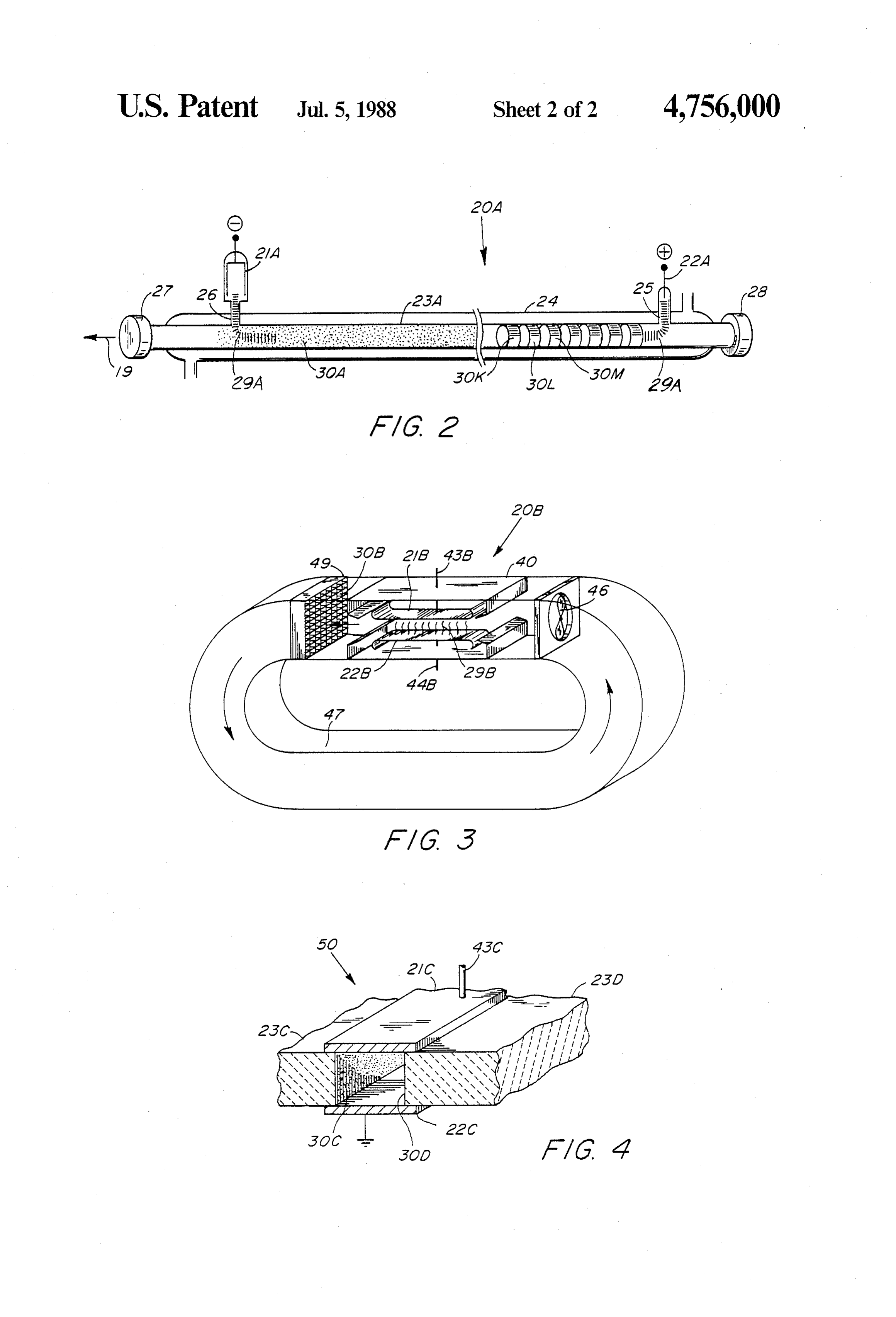
, mechanical processes. (1) Atomic oxygen: O-2.6 ev (endothermic 250 5 FIG. 2 is a side view diagram of a conventional CO2 KJ/mol) laser broken into two sections to demonstrate two dif (2) Ozone: O3- 1.5 ev (endothermic 140 KJ/mol) ferent placement methods for the catalyst. (3) Excited oxygen: O2-1 ev (endothermic 92 FIG. 3 is a perspective view of a convective flow KJ/mol)
CO2 laser incorporating the catalyst. 45 (4) Excited oxygen: O2*~1.6 ev (endothermic 154
FIG. 4 is a perspective cross sectioned view of a KJ/mol) portion of a waveguide laser. Besides, the above neutral forms of energetic oxygen, DESCRIPTION OF THE PREFERRED there are also various ionized sources of energetic oxy EMBODIMENTS gen which have been identified in the CO2 laser dis 50 charge. The major positively charged ions which can
The CO-O2 reaction is exothermic, but does not also serve as a source of oxygen are: proceed at ambient temperature because there is a large activation energy associated with the initiation of the O2, O, and NOt.
reaction. A non-catalytic material, such as aluminum oxide must be heated to 1000 K. in a CO and O2 gas 55 The positively charged ions are partially attracted to mixture for this reaction to proceed. Even at 1000 C. the walls of the discharge cavity to neutralize the elec only a small percentage of the thermally excited mole tron diffusion to these walls. Finally, it is possible that cules achieve a high enough energy to overcome this the ultraviolet light generated in a discharge can be activation energy and oxidize the CO to CO2. This is an absorbed by certain solids in a way as to create "hot' example of a thermally driven chemical reaction be 60 electrons which can disassociate O2 into atomic oxygen cause the kinetic energy of the molecules is used to on the surface of the solid. (See “Ultraviolet Light Stim overcome the activation energy. The activation energy ulated Thermal Oxidation of Silicon' E. M. Young, for oxidation of CO by O2 is estimated to be in excess of Appl. Phys. Lett.) Of all the energetic forms of oxygen 1.5 electron volts.
mentioned, atomic oxygen is probably the most impor
Even the use of catalysts, such as platinum, paladium, 65 tant cobalt oxide and Hopcalite depend only on heat (kinetic because of its abundance and reactivity. energy of the molecules) to overcome the activation ozone are All of these neutral and ionized species except for energy. The catalyst merely reduced this activation the reducedusually deactivated with a wall collision. At gas pressure and discharge cavity size of a
Page 6
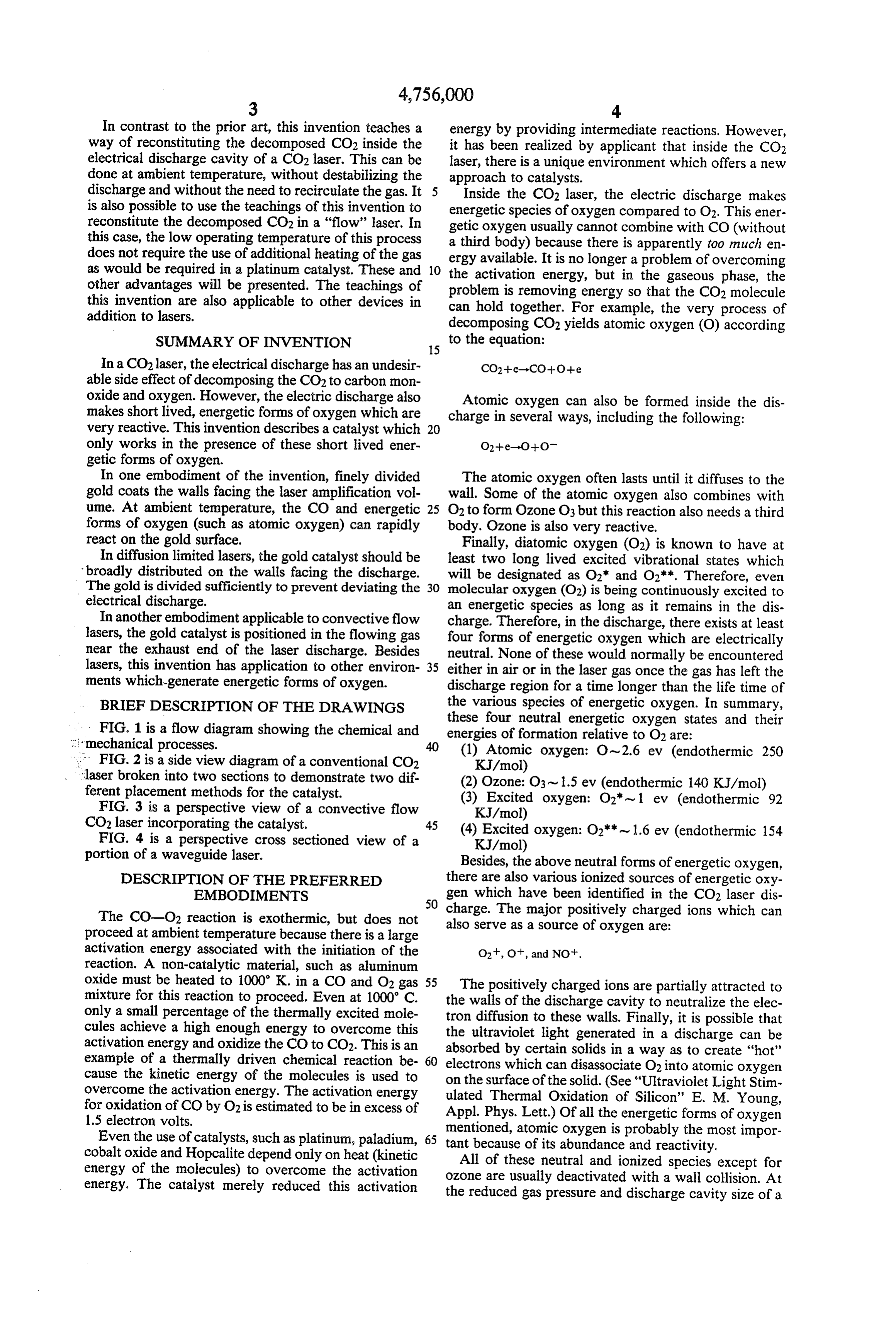
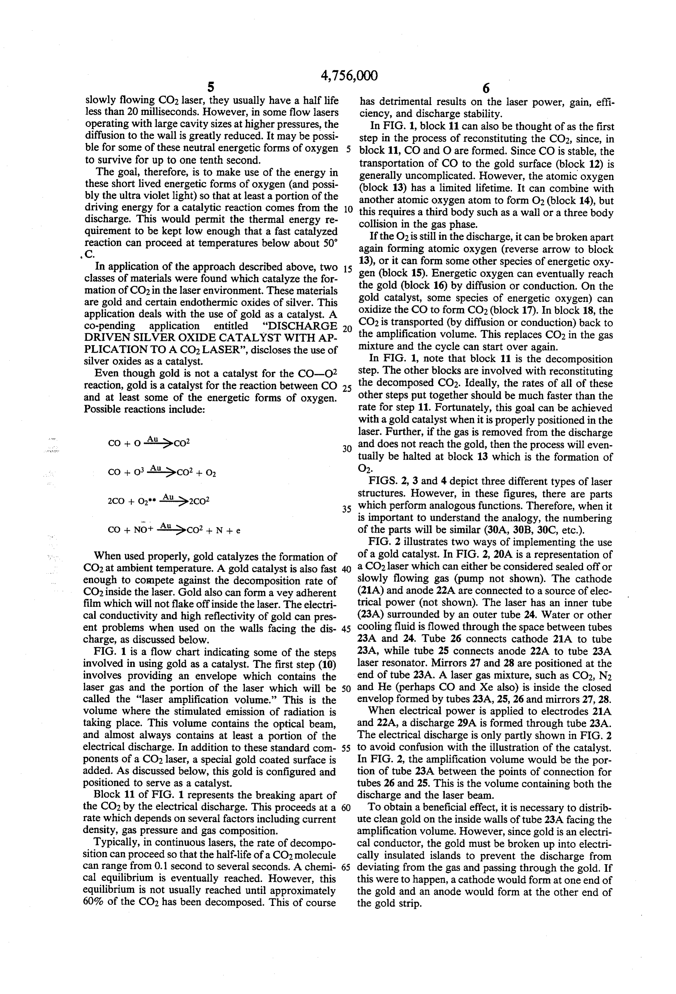
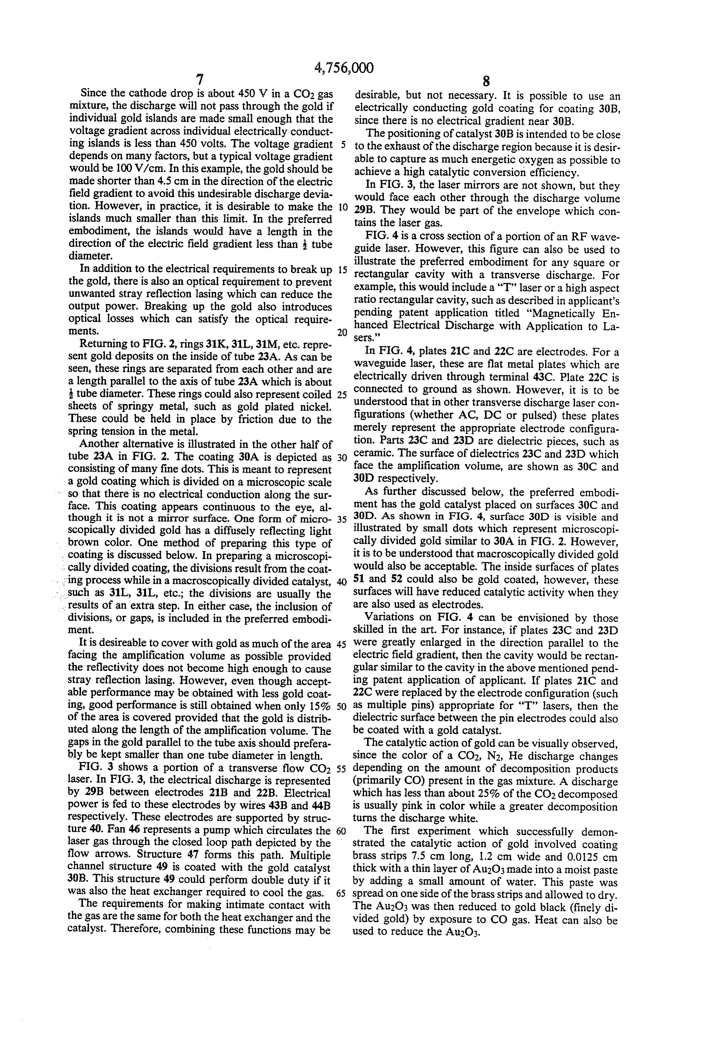
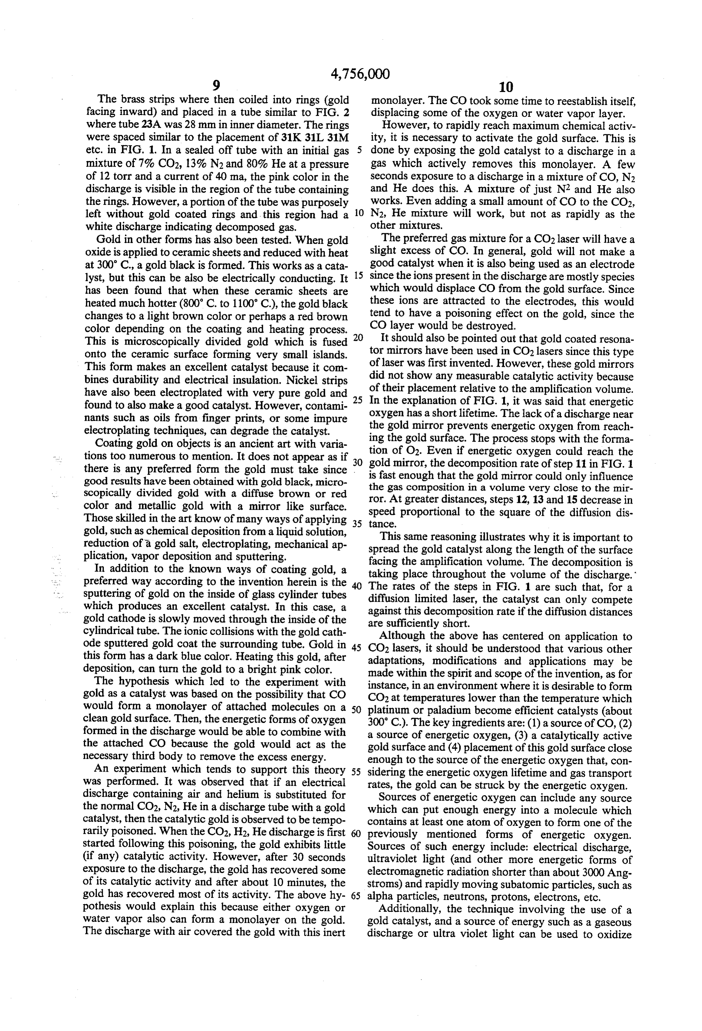
slowly flowing CO2 laser, they usually have a half life has detrimental results on the laser power, gain, effi less than 20 milliseconds. However, in some flow lasers ciency, and discharge stability. operating with large cavity sizes at higher pressures, the In FIG. 1, block 11 can also be thought of as the first diffusion to the wall is greatly reduced. It may be possi step in the process of reconstituting the CO2, since, in ble for some of these neutral energetic forms of oxygen block 11, CO and O are formed. Since CO is stable, the to survive for up to one tenth second. transportation of CO to the gold surface (block 12) is The goal, therefore, is to make use of the energy in generally uncomplicated. However, the atomic oxygen these short lived energetic forms of oxygen (and possi (block 13) has a limited lifetime. It can combine with bly the ultra violet light) so that at least a portion of the driving energy for a catalytic reaction comes from the 10 another this atomic oxygen atom to form O2 (block 14), but requires a third body such as a wall or a three body discharge. This would permit the thermal energy re collision in the gas phase. quirement to be kept low enough that a fast catalyzed If the O2 is still in the discharge, it can be broken apart reaction can proceed at temperatures below about 50 again forming atomic oxygen (reverse arrow to block
In application of the approach described above, two 15 gen 13), or it can form some other species of energetic oxy classes of materials were found which catalyze the for the gold (block 15). Energetic oxygen can eventually reach mation of CO2 in the laser environment. These materials gold catalyst, (block 16) by diffusion or conduction. On the are gold and certain endothermic oxides of silver. This some species of energetic oxygen) can application deals with the use of gold as a catalyst. A oxidize the CO to form CO2 (block 17). In block 18, the co-pending application entitled "DISCHARGE 20 the CO2 is transported (by diffusion or conduction) back to DRIVEN SILVER OXIDE CATALYST WITH AP amplification volume. This replaces CO2 in the gas PLICATION TO A CO2 LASER', discloses the use of mixture and the cycle can start over again.
silver oxides as a catalyst. In FIG. 1, note that block 11 is the decomposition Even though gold is not a catalyst for the CO-O. step. The other blocks are involved with reconstituting reaction, gold is a catalyst for the reaction between CO 25 the decomposed CO2. Ideally, the rates of all of these and at least some of the energetic forms of oxygen. other steps put together should be much faster than the Possible reactions include: rate for step 11. Fortunately, this goal can be achieved with a gold catalyst when it is properly positioned in the laser. Further, if the gas is removed from the discharge
Co+ o-Ausco? 30 and does not reach the gold, then the process will even tually be halted at block 13 which is the formation of
Co+ o-Ause CO2 + o, O2.
FIGS. 2, 3 and 4 depict three different types of laser
All Ge2CO2 2Co+ o-Al structures. However, in these figures, there are parts 35 which perform analogous functions. Therefore, when it is important to understand the analogy, the numbering
CO + Not AusCO2 + N + e of the parts will be similar (30A, 30B, 30C, etc.). FIG. 2 illustrates two ways of implementing the use
When used properly, gold catalyzes the formation of of a gold catalyst. In FIG. 2, 20A is a representation of CO2 at ambient temperature. A gold catalyst is also fast 40 a CO2 laser which can either be considered sealed off or enough to compete against the decomposition rate of slowly flowing gas (pump not shown). The cathode CO2 inside the laser. Gold also can form a vey adherent (21A) and anode 22A are connected to a source of elec film which will not flake off inside the laser. The electri trical power (not shown). The laser has an inner tube cal conductivity and high reflectivity of gold can pres (23A) surrounded by an outer tube 24. Water or other ent problems when used on the walls facing the dis 45 cooling fluid is flowed through the space between tubes charge, as discussed below. 23A and 24. Tube 26 connects cathode 21A to tube FIG. 1 is a flow chart indicating some of the steps 23A, while tube 25 connects anode 22A to tube 23A involved in using gold as a catalyst. The first step (10) laser resonator. Mirrors 27 and 28 are positioned at the involves providing an envelope which contains the end of tube 23A. A laser gas mixture, such as CO2, N2 laser gas and the portion of the laser which will be 50 and He (perhaps CO and Xe also) is inside the closed called the "laser amplification volume.” This is the envelop formed by tubes 23A, 25, 26 and mirrors 27, 28. volume where the stimulated emission of radiation is When electrical power is applied to electrodes 21A taking place. This volume contains the optical beam, and 22A, a discharge 29A is formed through tube 23A. and almost always contains at least a portion of the The electrical discharge is only partly shown in FIG. 2 electrical discharge. In addition to these standard com 55 to avoid confusion with the illustration of the catalyst. ponents of a CO2 laser, a special gold coated surface is In FIG. 2, the amplification volume would be the por added. As discussed below, this gold is configured and tion of tube 23A between the points of connection for positioned to serve as a catalyst. tubes 26 and 25. This is the volume containing both the Block 11 of FIG. 1 represents the breaking apart of discharge and the laser beam.
the CO2 by the electrical discharge. This proceeds at a 60 To obtain a beneficial effect, it is necessary to distrib rate which depends on several factors including current ute clean gold on the inside walls of tube 23A facing the density, gas pressure and gas composition. amplification volume. However, since gold is an electri Typically, in continuous lasers, the rate of decompo cal conductor, the gold must be broken up into electri sition can proceed so that the half-life of a CO2 molecule cally insulated islands to prevent the discharge from can range from 0.1 second to several seconds. A chemi 65 deviating from the gas and passing through the gold. If cal equilibrium is eventually reached. However, this this were to happen, a cathode would form at one end of equilibrium is not usually reached until approximately the gold and an anode would form at the other end of 60% of the CO2 has been decomposed. This of course the gold strip.
Page 7
Since the cathode drop is about 450 V in a CO2 gas desirable, but not necessary. It is possible to use an mixture, the discharge will not pass through the gold if electrically conducting gold coating for coating 30B, individual gold islands are made small enough that the since there is no electrical gradient near 30B, voltage gradient across individual electrically conduct The positioning of catalyst 30B is intended to be close ing islands is less than 450 volts. The voltage gradient to the exhaust of the discharge region because it is desir depends on many factors, but a typical voltage gradient able to capture as much energetic oxygen as possible to would be 100 V/cm. In this example, the gold should be achieve a high catalytic conversion efficiency. made shorter than 4.5 cm in the direction of the electric In FIG. 3, the laser mirrors are not shown, but they field gradient to avoid this undesirable discharge devia would face each other through the discharge volume tion. However, in practice, it is desirable to make the 10 islands much smaller than this limit. In the preferred 29B. They would be part of the envelope which con tains the laser gas.
embodiment, the islands would have a length in the FIG. 4 is a cross section of a portion of an RF wave direction of the electric field gradient less than tube guide laser. However, this figure can also be used to diameter.
In addition to the electrical requirements to break up 15 illustrate the preferred embodiment for any square or the gold, there is also an optical requirement to prevent example, thiscavity rectangular would with a transverse discharge. For include a "T" laser or a high aspect unwanted stray reflection lasing which can reduce the ratio rectangular cavity, such as described in applicant's output power. Breaking up the gold also introduces pending patent application optical losses which can satisfy the optical require hanced Electrical Discharge titled with
Application to La
Returning to FIG. 2, rings 31 K, 31L, 31M, etc. repre sers.' In FIG. 4, plates 21C and 22C are electrodes. For a sent gold deposits on the inside of tube 23A. As can be seen, these rings are separated from each other and are waveguide laser, these are flat metal plates which are a length parallel to the axis of tube 23A which is about connected todriven electrically through terminal 43C. Plate 22C is ground as shown. However, it is to be tube diameter. These rings could also represent coiled 25 understood that in other transverse discharge laser con sheets of springy metal, such as gold plated nickel. figurations
These could be held in place by friction due to the merely (whether AC, DC or pulsed) these plates spring tension in the metal. represent the appropriate electrode configura Another alternative is illustrated in the other half of tion. Parts 23C and 23D are dielectric pieces, such as tube 23A in FIG. 2. The coating 30A is depicted as 30 ceramic. The surface of dielectrics 23C and 23D which consisting of many fine dots. This is meant to represent face the amplification volume, are shown as 30C and a gold coating which is divided on a microscopic scale 30D respectively.
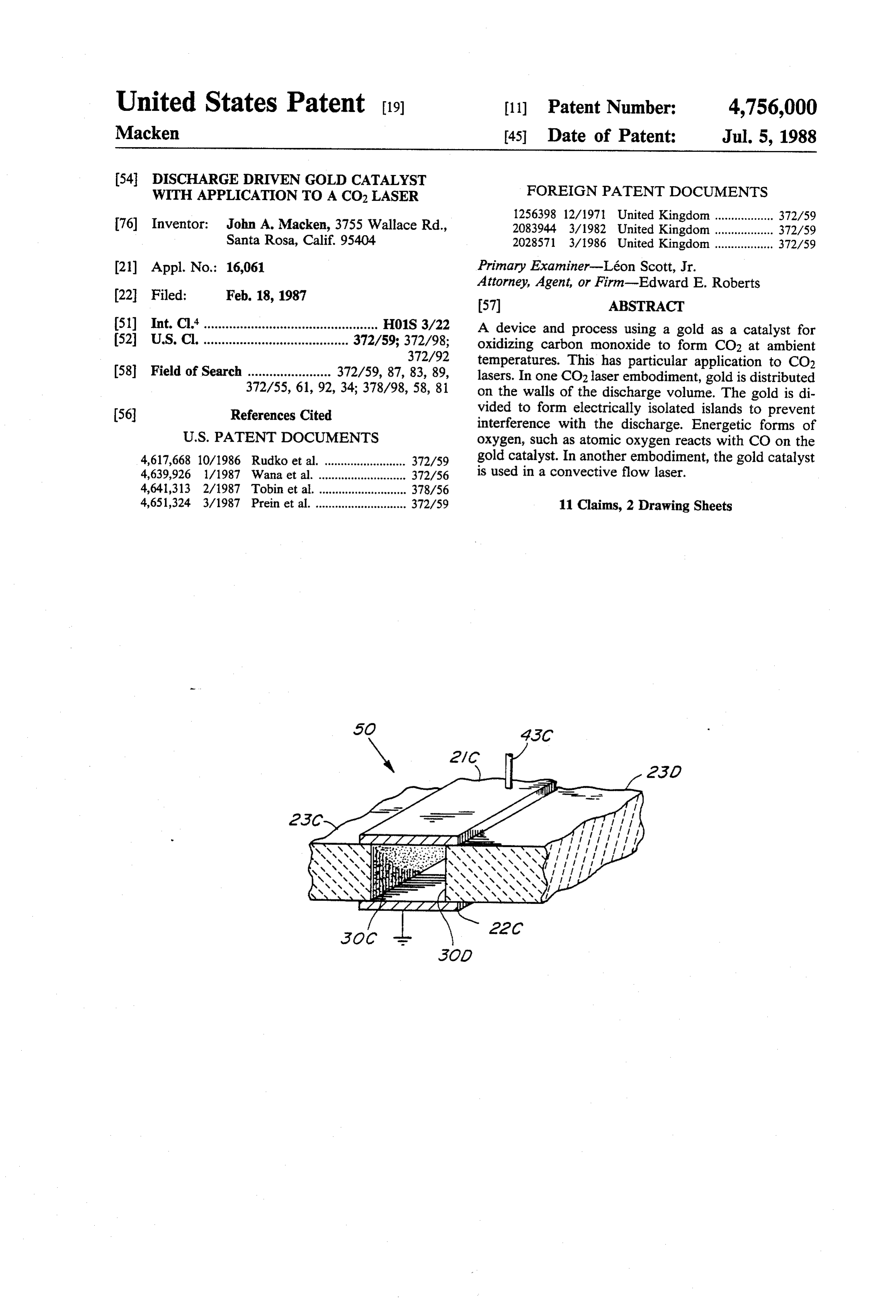
- so that there is no electrical conduction along the sur As further discussed below, the preferred embodi face. This coating appears continuous to the eye, al ment has the gold catalyst placed on surfaces 30C and though it is not a mirror surface. One form of micro 35 30D. As shown in FIG. 4, surface 30D is visible and scopically divided gold has a diffusely reflecting light illustrated by small dots which represent microscopi brown color. One method of preparing this type of cally divided gold similar to 30A in FIG. 2. However, coating is discussed below. In preparing a microscopi it is to be understood that macroscopically divided gold . . cally divided coating, the divisions result from the coat would also be acceptable. The inside surfaces of plates ging process while in a macroscopically divided catalyst, 40 51 and 52 could also be gold coated, however, these - such as 31L, 31L, etc.; the divisions are usually the surfaces will have reduced catalytic activity when they results of an extra step. In either case, the inclusion of are also used as electrodes.
divisions, or gaps, is included in the preferred embodi Variations on FIG. 4 can be envisioned by those ment. skilled in the art. For instance, if plates 23C and 23D It is desireable to cover with gold as much of the area 45 were greatly enlarged in the direction parallel to the facing the amplification volume as possible provided electric field gradient, then the cavity would be rectan the reflectivity does not become high enough to cause gular similar to the cavity in the above mentioned pend stray reflection lasing. However, even though accept ing patent application of applicant. If plates 21C and able performance may be obtained with less gold coat 22C were replaced by the electrode configuration (such ing, good performance is still obtained when only 15% SO as multiple pins) appropriate for "T" lasers, then the of the area is covered provided that the gold is distrib dielectric surface between the pin electrodes could also uted along the length of the amplification volume. The be coated with a gold catalyst.
gaps in the gold parallel to the tube axis should prefera The catalytic action of gold can be visually observed, bly be kept smaller than one tube diameter in length. since the color of a CO2, N2, He discharge changes FIG. 3 shows a portion of a transverse flow CO2 55 depending on the amount of decomposition products laser. In FIG. 3, the electrical discharge is represented (primarily CO) present in the gas mixture. A discharge by 29B between electrodes 21B and 22B. Electrical which has less than about 25% of the CO2 decomposed power is fed to these electrodes by wires 43B and 44B is usually pink in color while a greater decomposition respectively. These electrodes are supported by struc turns the discharge white.
ture 40. Fan 46 represents a pump which circulates the 60 The first experiment which successfully demon laser gas through the closed loop path depicted by the strated the catalytic action of gold involved coating flow arrows. Structure 47 forms this path. Multiple brass strips 7.5 cm long, 1.2 cm wide and 0.0125 cm channel structure 49 is coated with the gold catalyst thick with a thin layer of Au2O3 made into a moist paste 30B. This structure 49 could perform double duty if it by adding a small amount of water. This paste was was also the heat exchanger required to cool the gas. 65 spread on one side of the brass strips and allowed to dry. The requirements for making intimate contact with The Au2O3 was then reduced to gold black (finely di the gas are the same for both the heat exchanger and the vided gold) by exposure to CO gas. Heat can also be catalyst. Therefore, combining these functions may be used to reduce the Au2O3.
Page 8
The brass strips where then coiled into rings (gold monolayer. The CO took some time to reestablish itself, facing inward) and placed in a tube similar to FIG. 2 displacing some of the oxygen or water vapor layer. where tube 23A was 28 mm in inner diameter. The rings However, to rapidly reach maximum chemical activ were spaced similar to the placement of 31K 31L 31M ity, it is necessary to activate the gold surface. This is etc. in FIG. 1. In a sealed off tube with an initial gas done by exposing the gold catalyst to a discharge in a mixture of 7% CO2, 13% N2 and 80%. He at a pressure gas which actively removes this monolayer. A few of 12 torr and a current of 40 ma, the pink color in the seconds exposure to a discharge in a mixture of CO, N2 discharge is visible in the region of the tube containing and He does this. A mixture of just N2 and He also the rings. However, a portion of the tube was purposely works. Even adding a small amount of CO to the CO2, left without gold coated rings and this region had a 10 N2, He mixture will work, but not as rapidly as the white discharge indicating decomposed gas. other mixtures.
Gold in other forms has also been tested. When gold The preferred gas mixture for a CO2 laser will have a oxide is applied to ceramic sheets and reduced with heat slight excess of CO. In general, gold will not make a at 300° C., a gold black is formed. This works as a cata 15 good catalyst when it is also being used as an electrode lyst, but this can be also be electrically conducting. It since the ions present in the discharge are mostly species has been found that when these ceramic sheets are which would displace CO from the gold surface. Since heated much hotter (800 C. to 1100° C), the gold black these ions are attracted to the electrodes, this would changes to a light brown color or perhaps a red brown tend to have a poisoning effect on the gold, since the color depending on the coating and heating process. CO layer would be destroyed.
This is microscopically divided gold which is fused 20 It should also be pointed out that gold coated resona onto the ceramic surface forming very small islands. tor mirrors have been used in CO2 lasers since this type This form makes an excellent catalyst because it com of laser was first invented. However, these gold mirrors bines durability and electrical insulation. Nickel strips of did not show any measurable catalytic activity because have also been electroplated with very pure gold and 25 In their placement relative to the amplification volume. the explanation of FIG. 1, it was said that energetic found to also make a good catalyst. However, contami oxygen nants such as oils from finger prints, or some impure the goldhas a short lifetime. The lack of a discharge near mirror prevents energetic oxygen from reach electroplating techniques, can degrade the catalyst.
Coating gold on objects is an ancient art with varia ing the gold surface. The process stops with the forma tions too numerous to mention. It does not appear as if 30 tion of O2. Even if energetic oxygen could reach the there is any preferred form the gold must take since isgold fast mirror, the decomposition rate of step 11 in FIG. 1 enough that the gold mirror could only influence good results have been obtained with gold black, micro scopically divided gold with a diffuse brown or red the gas composition in a volume very close to the mir ror. At greater distances, steps 12, 13 and 15 decrease in color and metallic gold with a mirror like surface. speed
Those skilled in the art know of many ways of applying 35 tance. proportional to the square of the diffusion dis gold, such as chemical deposition from a liquid solution, This same reasoning illustrates why it is important to reduction of a gold salt, electroplating, mechanical ap spread the gold catalyst along the length of the surface plication, vapor deposition and sputtering.
In addition to the known ways of coating gold, a taking placeamplification facing the volume. The decomposition is preferred way according to the invention herein is the The rates of the steps inthe throughout volume of the discharge.
FIG. 1 are such that, for a sputtering of gold on the inside of glass cylinder tubes diffusion limited laser, the catalyst which produces an excellent catalyst. In this case, a against this decomposition rate if the can only compete diffusion distances gold cathode is slowly moved through the inside of the are sufficiently short.
cylindrical tube. The ionic collisions with the gold cath Although the above has centered on application to ode sputtered gold coat the surrounding tube. Gold in 45 CO2 lasers, it should be understood that various other this form has a dark blue color. Heating this gold, after adaptations, modifications and applications may be deposition, can turn the gold to a bright pink color. made within the spirit and scope of the invention, as for The hypothesis which led to the experiment with instance, in an environment where it is desirable to form gold as a catalyst was based on the possibility that CO CO2 at temperatures lower than the temperature which would form a monolayer of attached molecules on a 50 platinum or paladium become efficient catalysts (about clean gold surface. Then, the energetic forms of oxygen 300' C.). The key ingredients are: (1) a source of CO, (2) formed in the discharge would be able to combine with a source of energetic oxygen, (3) a catalytically active the attached CO because the gold would act as the gold surface and (4) placement of this gold surface close necessary third body to remove the excess energy. enough to the source of the energetic oxygen that, con An experiment which tends to support this theory 55 sidering the energetic oxygen lifetime and gas transport was performed. It was observed that if an electrical rates, the gold can be struck by the energetic oxygen. discharge containing air and helium is substituted for Sources of energetic oxygen can include any source the normal CO2, N2, He in a discharge tube with a gold which can put enough energy into a molecule which catalyst, then the catalytic gold is observed to be tempo contains at least one atom of oxygen to form one of the rarily poisoned. When the CO2, H2, He discharge is first previously mentioned forms of energetic oxygen. started following this poisoning, the gold exhibits little Sources of such energy include: electrical discharge, (if any) catalytic activity. However, after 30 seconds ultraviolet light (and other more energetic forms of exposure to the discharge, the gold has recovered some electromagnetic radiation shorter than about 3000 Ang of its catalytic activity and after about 10 minutes, the stroms) and rapidly moving subatomic particles, such as gold has recovered most of its activity. The above hy 65 alpha particles, neutrons, protons, electrons, etc. pothesis would explain this because either oxygen or Additionally, the technique involving the use of a water vapor also can form a monolayer on the gold. gold catalyst, and a source of energy such as a gaseous The discharge with air covered the gold with this inert discharge or ultra violet light can be used to oxidize
Page 9
certain types of other molecules. These other molecules promote the catalytic formation of CO2 in at least a would have to fit the criteria of being a gas at a pressure substantial portion of said laser gas mixture in said an greater than 0.1 torr, have an oxygen atom in the mole plification volume.
cule and also having this oxygen atom located in such a 3. The combination according to claim 2 where said position in the molecule as to be able to form an attach gold catalyst is supported by a dielectric material and ment site to gold. where said gold catalyst forms multiple, generally mi While the above has centered on a laser oscillator, the croscopic regions which are electrically insulated from teachings herein apply equally well to a laser amplifier. each other.
Therefore, to cover both these categories, the term 4. The combination according to claim 2 where said "laser device' is appropriate. Additionally, the gas in a 10 gold catalyst has been divided into multiple, generally CO2 laser has been mentioned herein as made up of macroscopic, regions which are electrically insulated CO2, N2 and He. This was only mentioned as an exam from each other.
ple. It is to be understood that other gas mixtures, such 5. The combination according to claim 1 wherein said as CO2, CO, He, are also commonly use in sealed off gold catalyst and said electrode are different. lasers. Other gas additives include Xe, H2O, D2, Ar, etc. 15 6. The
The teachings herein apply to these and other CO2 laser said gold combination according to claim 5 wherein the mixtures. Further, in rating the effectiveness of a cata laser resonator reflector. independently as part of a catalyst functions lyst, it is grammatically easier to talk about minimizing 7. The combination according to claim 1 wherein said the decomposition products rather than maximizing the CO2 laser device has said gas mixture rapidly flowing amount of CO2. In particular, it is desirable to minimize through
said amplification volume and where said gold the amount of oxygen in the amplification volume be coated surface is a relatively large surface area structure cause oxygen has a detrimental effect on the laser out designed to make intimate contact with said flowing gas put power and discharge stability.
In some CO2 lasers, a portion of the laser light reflects of said amplification volumeclose and positioned sufficiently
to the gas exhaust end be contacted by a sub off the walls of the cavity. An example of this would be 25 stantial amount of said energetic oxygen. the walls of a waveguide laser. While these walls func operation, said gold catalyzes the formationFurther, in
tion as a type of reflector, this is distinctly different the extent that there is a substantial reduction in the from the laser resonator mirrors such as 27 and 28 in
FIG. 2. A gold surface can simultaneously function as a total molecular oxygen in the amplification volume catalyst and reflector for wall reflection. However, as 30 1ng. compared to the oxygen content without said gold coat previously stated, gold coated resonator mirrors are not properly positioned to also function as an effective cata 8. In a method for converting carbon monoxide and lyst. oxygen to CO2 the steps in no particular order compris While there has been shown and described a pre 1ng:
ferred embodiment, it is to be understood that other 35 provide a means for forming at least one energetic modifications may be made without departing from the form of oxygen;
spirit and scope of the invention. provide a gold coated surface positioned so as to I claim: promote contact with both said carbon monoxide 1. A CO2 laser device including a closed envelope and said energetic form of oxygen for the purposes containing a CO2 laser gas mixture and laser amplifica of making catalytic formation of CO2. tion volume, said amplification volume including an 9. The method of claim 8 where the step of providing electrical discharge through said CO2 laser gas mixture, a means for forming at least one energetic form of oxy said discharge causing decomposition of CO2 in said gen includes the step of providing energy to a source of mixture to form carbon monoxide, oxygen, and ener oxygen, said energy means selected from the group getic forms of oxygen, the improved feature compris 45 consisting of:
1ng: - an electrical discharge, electromagnetic radiation inside said envelope there is at least one surface shorter than 3000 Angstroms wavelength, or rap coated with gold; idly moving subatomic particles. said gold surface is positioned and configured as to 10. The method of claim 9 where the step of provid promote contact with both said carbon monoxide 50 ing an energy source includes providing an electric and said energetic forms of oxygen generated in discharge in a CO2 laser device.
said amplification volume for purposes of cataliz 11. The method of claim 8 where the step of provid ing formation of CO2. ing a gold coated surface includes supporting said gold 2. The combination according to claim 1 wherein the surface with a dielectric material and also dividing said said gold catalyst is on at least a portion of the wall area 55 gold surface in such a way as to form multiple electri facing said amplification volume, said gold is distributed cally insulated islands of gold.
over a sufficiently broad area of said well area so as to sit
Provenance
- Collection
- Cited prior art
- Original PDF
- patentimages.storage.googleapis.com →
- Filed
- 1987-02-18
- Pages
- 9
- Method
- pdftotext (the PDF's own text layer) + pdftoppm 300dpi page scans
- Source
- Google Patents bibliographic record
- Granted
- 1988-07-05
- Inventors
- John A. Macken
- Transcribed from
- patentimages.storage.googleapis.com →