patent · US4257556
Fluid heat transfer system
24 March 1981
Page 1 — bibliographic record
United States Patent (19) 11) 4,257,556 Skala 45) Mar. 24, 1981
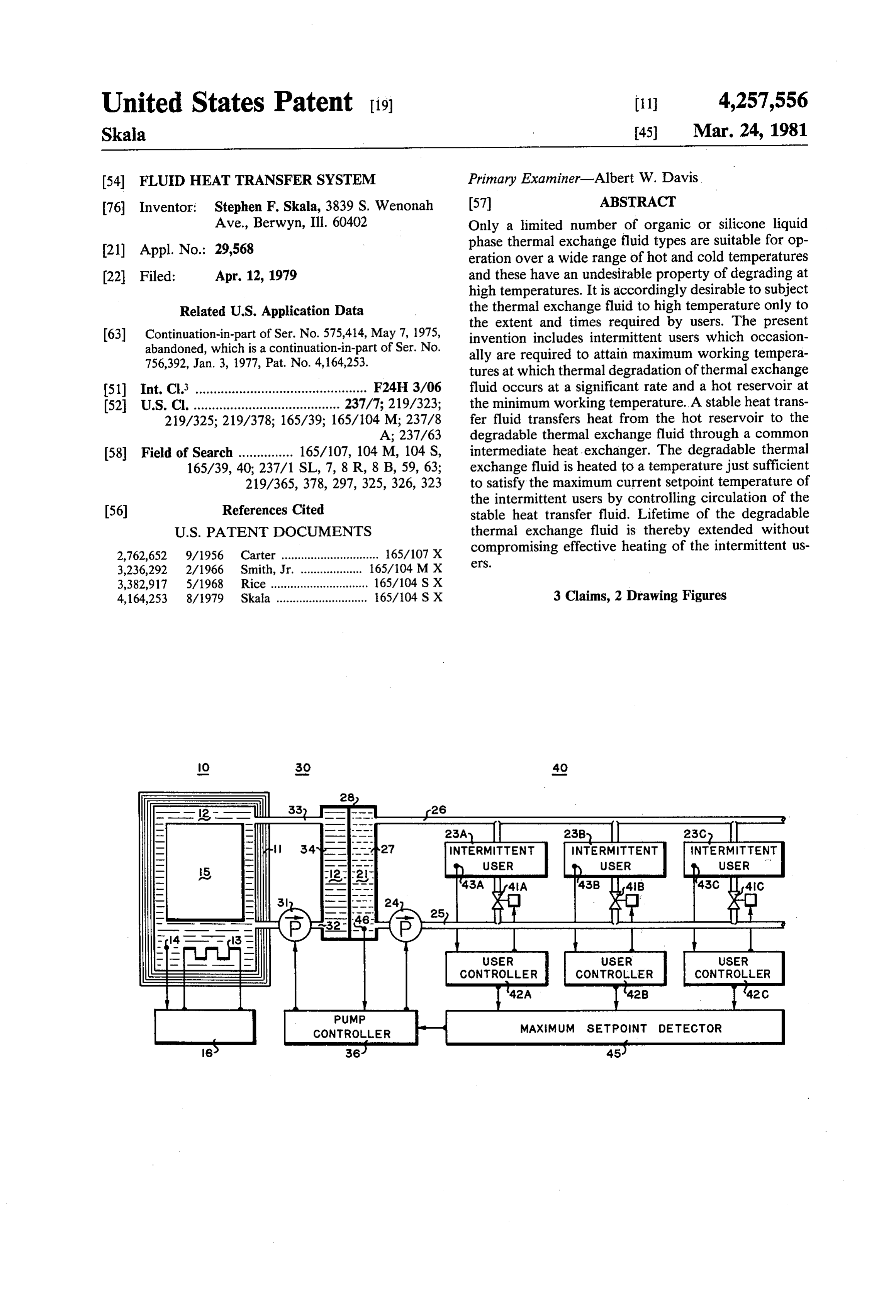
54 FLUID HEAT TRANSFER SYSTEM Primary Examiner-Albert W. Davis 76 Inventor: Stephen F. Skala, 3839 S. Wenonah (57) ABSTRACT Ave., Berwyn, Ill. 60402 Only a limited number of organic or silicone liquid (21) Appl. No.: 29,568 phase thermal exchange fluid types are suitable for op eration over a wide range of hot and cold temperatures 22 Filed: Apr. 12, 1979 and these have an undesirable property of degrading at high temperatures. It is accordingly desirable to subject
Relateda U.S. Application Data E. thermai change fluid to g tratee present the extent and times require y users.
only to (63) abandoned,
Continuation-in-part of Ser: No. 575:1, May 15, which is a continuation-in-part of Ser. No.
invention includes
intermittent users which occasion 756,392, Jan. 3, 1977, Pat. No. 4,164,253. ally are required to attain maximum working tempera was y aWI tures at which thermal degradation of thermal exchange (51) Int. Cl. ............................................... F24H 3/06 fluid occurs at a significant rate and a hot reservoir at 52 U.S. C. ........................................ 237/7; 219/323; the minimum working temperature. A stable heat trans 219/325; 219/378; 165/39; 165/104 M; 237/8 fer fluid transfers heat from the hot reservoir to the A; 237/63 degradable thermal exchange fluid through a common (58) Field of Search ............... 165/107, 104 M, 104 S, intermediate heat exchanger. The degradable thermal 165/39, 40; 237/1 SL, 7, 8 R, 8 B, 59, 63; exchange fluid is heated to a temperature just sufficient 219/365, 378, 297, 325, 326, 323 to satisfy the maximum current setpoint temperature of s the intermittent users by controlling circulation of the 56) References Cited stable heat transfer fluid. Lifetime of the degradable
2,762,652 9/1956 Carter .............................. so compromising
effective heating of the intermittent us 3,236,292 2/1966 Smith, Jr. ... 165/104 MX 3,382,917 5/1968 Rice ........... ... 165/104 SX 4,164,253 8/1979 Skala ............................ 65/104 S X 3 Claims, 2 Drawing Figures
INTERMITTENT INTERMITTENT
USER
CONTROLLER
Page 2
Drawing sheet — no readable text.
Page 3
Drawing sheet — no readable text.
Page 4
weeks of degradation products formed at temperatures
FLUID HEAT TRANSFER SYSTEM ranging from about 600 F. to 700" F. At 650 F., the more stable thermal exchange fluids have a degradation
The present application is a continuation-in-part of rate of approximately 1% per week. Most thermal ex application Ser. No. 575,414 filed May 7, 1975 now 5 change fluids have an activation energy such that their abandoned and of Ser. No. 756,302 filed Jan. 3, 1977 and degradation rate is doubled for every 18 F. increase in now U.S. Pat. No. 4,164,253. temperature. Accordingly, the following annual degra CROSS-REFERENCE TO RELATED dation rates are expected for lower temperatures: 600 APPLICATIONS F-6.5%/yr; 550 F-0.68%/yr. 500 F-0056%/yr;
Ser. No. 792,455 now U.S. Pat. No. 4,156,454 entitled 25 years is less than 0.1% so that continuous long term Oven with Refrigerated Food Storage Based on Ther operation at such lower temperatures would be satisfac mal Exchange Fluid. tory. For cooking appliances, however, the higher tem Ser. No. 908,509 now U.S. Pat. No.4,188,794 entitled peratures are occasionally required within the appliance Freezer with Rapid Defrosting. 15 and are useful for compensating for thermal impedances Ser. No. 941,123 entitled Pressure Cooking Appli in the system to attain desired high temperatures rap ance with Thermal Exchange Fluid. idly. A preferred maximum temperature of the thermal Ser. No. 839,618 now U.S. Pat. No. 4,173,993 entitled exchange fluid would be between 600 F. and 550 F. Domestic Applicance System with Thermal Exchange
Fluid. 20 OBJECTS BACKGROUND OF THE INVENTION It is a general object of this invention to provide an improved system for transferring heat by liquid phase
This invention relates to a system for transferring fluids from a hot reservoir to intermittent users. heat from a hot reservoir to a user by a thermal ex change fluid and having the particular freezer of ex 25 theItintermittent is a further object to provide effective heating of tending lifetime of the thermal exchange fluid which is temperatures andusers during working periods at high at other times to assure a satisfactory thermally degradable.
lifetime of a thermal exchange fluid which is thermally
The invention has particular application to a system degradable.
of domestic appliances wherein a single liquid phase thermal exchange fluid exchanges heat between the 30 SUMMARY appliances and both a hot reservoir and a cold reservoir. These and other objects and advantages which will The appliance system combines heating and cooling become capability in simple appliance units and accumulates two fluidapparent are attained by this invention wherein circuits function to transfer heat from a hot energy at off-peak hours and at low power levels for subsequent rapid release during peak use periods. These 35 reservoir by a stable heat transfer fluid through an inter and other characteristics of the appliance system are mediate heat exchanger to a thermally degradable ther mal exchange fluid which transfers heat to one or more described in more detail in the cited related applications intermittent and in the following patents. U.S. Pat. No. 3,888,303 users. The hot reservoir is maintained at describes a system of houseware units which are con temperatures which are at least the maximum working nectable to a source of thermal exchange fluid. U.S. Pat. 40 temperature of the intermittent users and at which ther No. 4,024,904 describes a range which exchanges heat mal degradation of the thermal exchange fluid would between a pot or pan surface and a thermal exchange occur at a significant rate. The intermittent users have periods of substantial duration at temperatures at which fluid in a heat exchanger by forced air convection.
Representative conditions to be satisfied by a thermal the thermal degradation is not significant. Circulation of exchange fluid include a temperature range of -20F. 45 the heat transfer fluid between the hot reservoir and the to 575 F. and a lifetime of more than 25 years without intermediate heat exchanger is controlled to transfer skilled preventive maintenance. The users operate inter heat to the degradable thermal exchange fluid to in mittently with infrequent excursions to maximum work crease its temperature to a level just sufficient to satisfy ing temperatures. Several commercial thermal ex current temperature requirements of the intermittent change fluid types having generally satisfactory heat 50 users. In a system having a plurality of intermittent transfer characteristics over the cited temperature users with each of the users controlled at its setpoint range have been designed for thermal stability, but even temperature by a servo valve which regulates flow of the most stable organic compounds change chemically the thermal exchange fluid, a maximum setpoint detec at high temperatures over long periods. Undesirable tor selects the maximum current setpoint to control the effects which result from oxidation, cracking, and for 55 circulation of the stable heat transfer fluid. mation of higher polymers at high temperatures include This system provides efficient heat storage in the hot vapor loss, viscosity increase and geling, and formation reservoir, effective heating of the intermittent users, of flow and heat impeding deposits. operation over a wide range of temperatures, and a Thermal degradation over long periods is estimated satisfactory lifetime of the thermally degradable ther conventionally from rates of undesirable effects occur 60 mal exchange fluid.
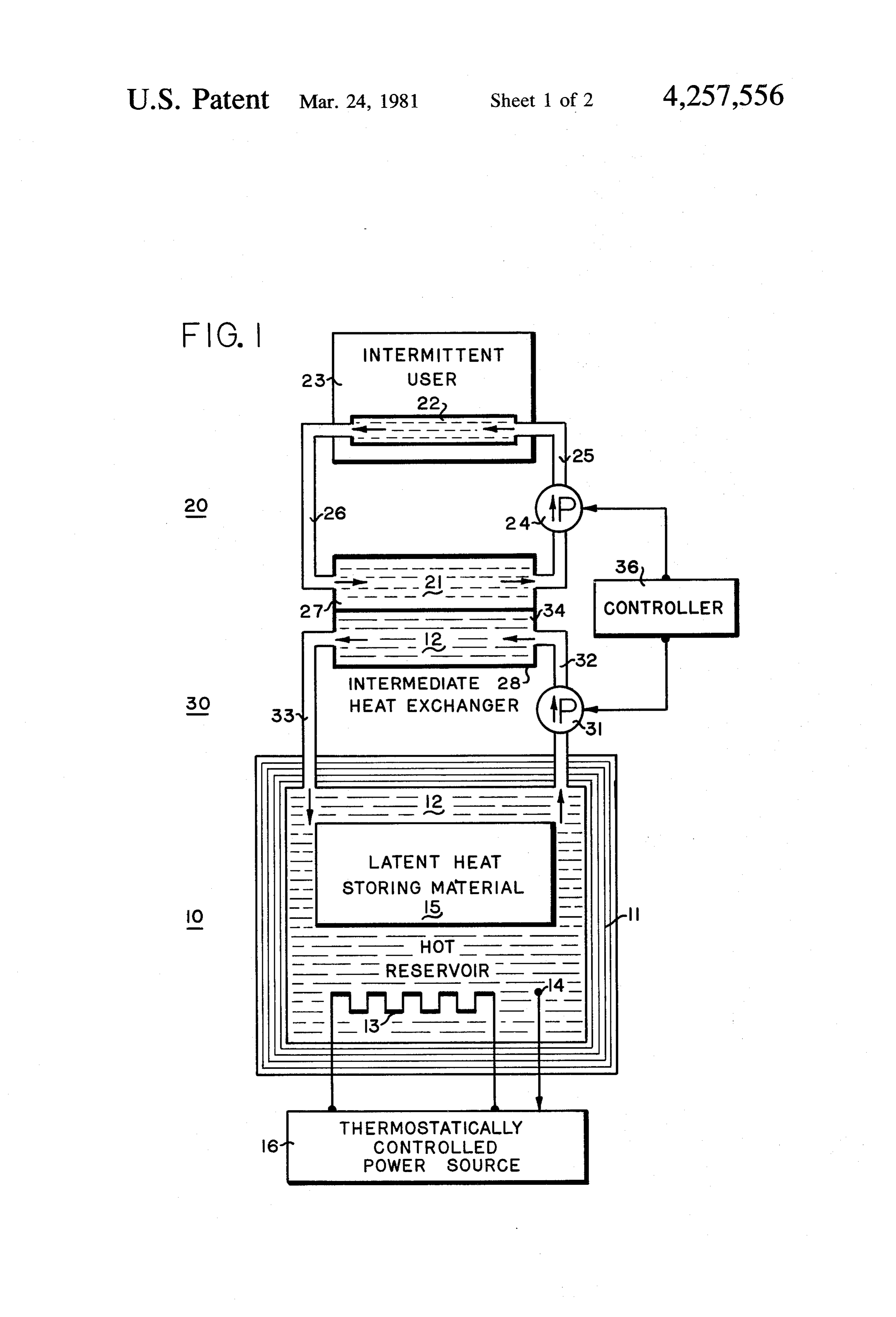
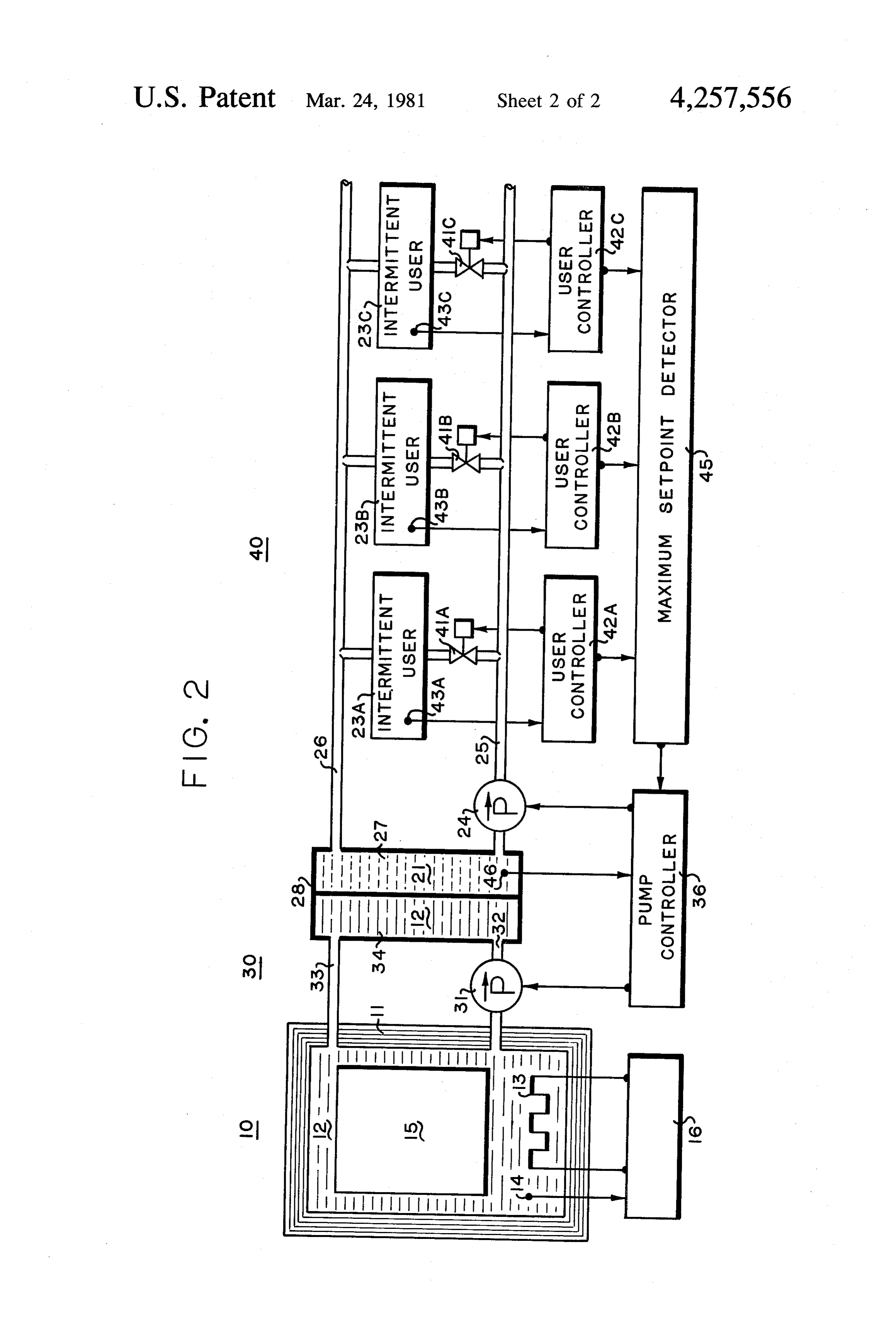
ing at higher temperatures over shorter periods. The DESCRIPTION OF THE DRAWINGS scaling relation is an Arrehenius equation, D= A el, where the constants A and activation energy E FIG. 1 is a diagrammatic drawing of an elementary are determined from a range of degradation rates D at embodiment of the system of the invention showing a temperatures T. Once the constants are determined, 65 hot reservoir, two fluid circuits having a common inter degradation rates at lower temperatures are calculated. mediate heat exchanger, an intermittent user, and means A representative accelerated test of a thermal exchange to control flow in the two fluid circuits according to the fluid is based on measurements over a period of several invention. m
Page 5
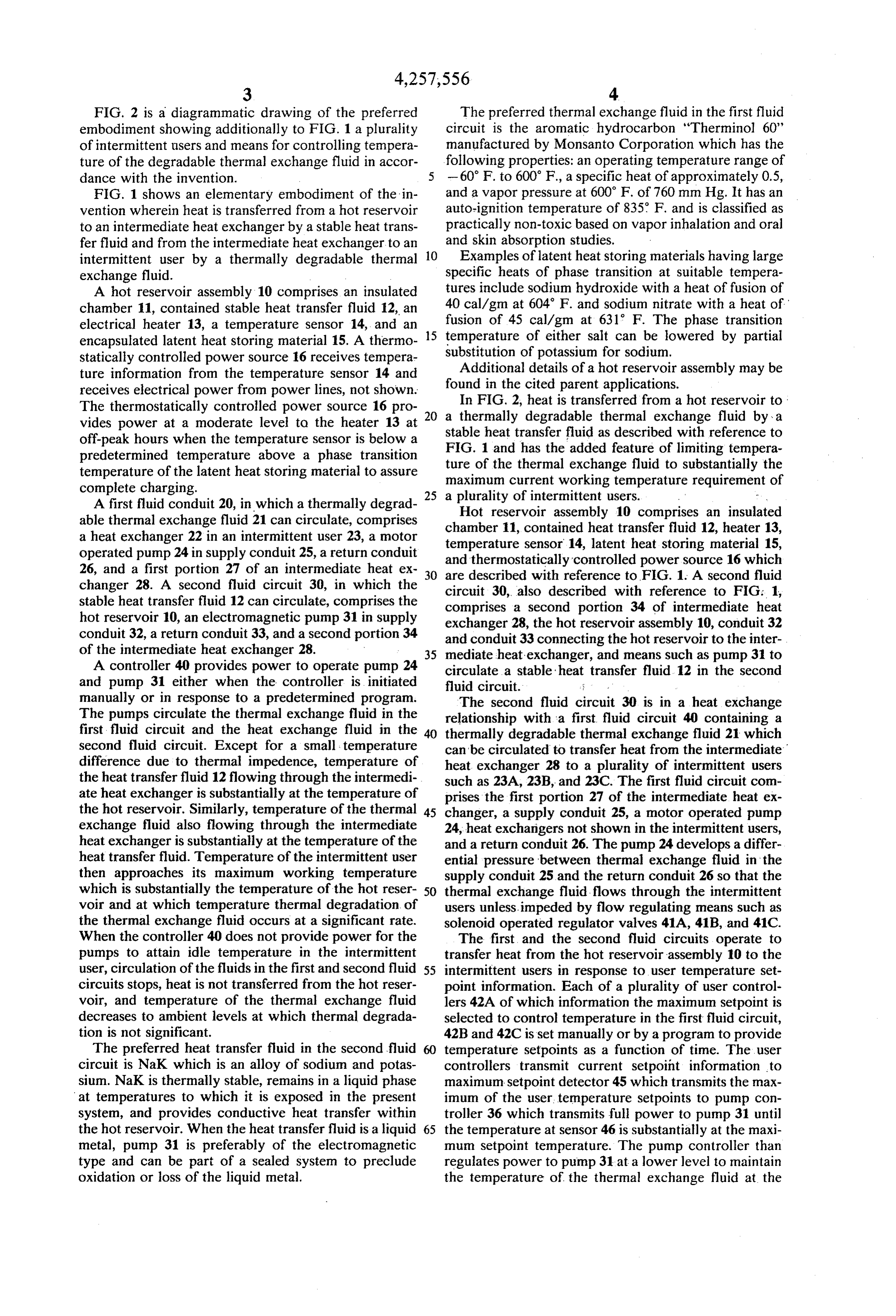
FIG. 2 is a diagrammatic drawing of the preferred The preferred thermal exchange fluid in the first fluid embodiment showing additionally to FIG. 1 a plurality circuit is the aromatic hydrocarbon "Therminol 60' of intermittent users and means for controlling tempera manufactured by Monsanto Corporation which has the ture of the degradable thermal exchange fluid in accor following properties: an operating temperature range of dance with the invention. 5 -60 F. to 600 F., a specific heat of approximately 0.5, FIG. 1 shows an elementary embodiment of the in and a vapor pressure at 600 F. of 760 mm Hg. It has an vention wherein heat is transferred from a hot reservoir auto-ignition temperature of 835 F. and is classified as to an intermediate heat exchanger by a stable heat trans practically non-toxic based on vapor inhalation and oral fer fluid and from the intermediate heat exchanger to an and skin absorption studies.
intermittent user by a thermally degradable thermal 10 Examples of latent heat storing materials having large exchange fluid. specific heats of phase transition at suitable tempera A hot reservoir assembly 10 comprises an insulated tures include sodium hydroxide with a heat of fusion of chamber 11, contained stable heat transfer fluid 12, an 40 cal/gm at 604 F. and sodium nitrate with a heat of electrical heater 13, a temperature sensor 14, and an fusion of 45 cal/gm at 631 F. The phase transition encapsulated latent heat storing material 15. A thermo 15 temperature of either salt can be lowered by partial statically controlled power source 16 receives tempera substitution of potassium for sodium.
ture information from the temperature sensor 14 and found Additional details of a hot reservoir assembly may be receives electrical power from power lines, not shown. in the cited parent applications. The thermostatically controlled power source 16 pro 20 a thermally2, degradable
In FIG. heat is transferred from a hot reservoir to:
vides power at a moderate level to the heater 13 at stable heat transfer fluid asthermal exchange fluid by a described with reference to off-peak hours when the temperature sensor is below a FIG. 1 and has the added feature of limiting tempera predetermined temperature above a phase transition ture of the thermal exchange fluid to substantially temperature of the latent heat storing material to assure maximum current working temperature requirementthe of complete charging. 25 a plurality of intermittent users. A first fluid conduit 20, in which a thermally degrad Hot reservoir assembly 10 comprises an insulated able thermal exchange fluid 21 can circulate, comprises chamber 11, contained heat transfer fluid 12, heater 13, a heat exchanger 22 in an intermittent user 23, a motor temperature sensor 14, latent heat storing material 15, operated pump 24 in supply conduit 25, a return conduit and thermostatically controlled power source 16 which 26, and a first portion 27 of an intermediate heat ex 30 are described with reference to FIG. 1. A second fluid changer 28. A second fluid circuit 30, in which the circuit 30, also described with reference to FIG: 1, stable heat transfer fluid 12 can circulate, comprises the comprises a second portion 34 of intermediate heat hot reservoir 10, an electromagnetic pump 31 in supply exchanger 28, the hot reservoir assembly 10, conduit 32 conduit 32, a return conduit 33, and a second portion 34 and conduit 33 connecting the hot reservoir to the inter of the intermediate heat exchanger 28. 35 mediate heat exchanger, and means such as pump 31 to A controller 40 provides power to operate pump 24 circulate a stable heat transfer fluid. 12 in the second and pump 31 either when the controller is initiated fluid circuit. , manually or in response to a predetermined program. The second fluid circuit 30 is in a heat exchange The pumps circulate the thermal exchange fluid in the relationship with a first fluid circuit 40 containing a first fluid circuit and the heat exchange fluid in the 40 thermally degradable thermal exchange fluid 21 which second fluid circuit. Except for a small temperature can be circulated to transfer heat from the intermediate difference due to thermal impedence, temperature of heat exchanger 28 to a plurality of intermittent users the heat transfer fluid 12 flowing through the intermedi such as 23A, 23B, and 23C. The first fluid circuit com ate heat exchanger is substantially at the temperature of prises the first portion 27 of the intermediate heat ex the hot reservoir. Similarly, temperature of the thermal 45 changer, a supply conduit 25, a motor operated pump exchange fluid also flowing through the intermediate 24, heat exchangers not shown in the intermittent users, heat exchanger is substantially at the temperature of the and a return conduit 26. The pump 24 develops a differ heat transfer fluid. Temperature of the intermittent user ential pressure between thermal exchange fluid in the then approaches its maximum working temperature supply conduit 25 and the return conduit 26 so that the which is substantially the temperature of the hot reser 50 thermal exchange fluid flows through the intermittent voir and at which temperature thermal degradation of users unless, impeded by flow regulating means such as the thermal exchange fluid occurs at a significant rate. solenoid operated regulator valves 41A, 41B, and 41C. When the controller 40 does not provide power for the The first and the second fluid circuits operate to pumps to attain idle temperature in the intermittent transfer heat from the hot reservoir assembly 10 to the user, circulation of the fluids in the first and second fluid 55 intermittent users in response to user temperature set circuits stops, heat is not transferred from the hot reser point information. Each of a plurality of user control voir, and temperature of the thermal exchange fluid lers 42A of which information the maximum setpoint is decreases to ambient levels at which thermal degrada selected to control temperature in the first fluid circuit, tion is not significant. 42B and 42C is set manually or by a program to provide The preferred heat transfer fluid in the second fluid temperature setpoints as a function of time. The user circuit is NaK which is an alloy of sodium and potas controllers transmit current setpoint information to sium. NaK is thermally stable, remains in a liquid phase maximum setpoint detector 45 which transmits the max at temperatures to which it is exposed in the present imum of the user, temperature setpoints to pump con system, and provides conductive heat transfer within troller 36 which transmits full power to pump 31 until the hot reservoir. When the heat transfer fluid is a liquid 65 the temperature at sensor 46 is substantially at the maxi metal, pump 31 is preferably of the electromagnetic mum setpoint temperature. The pump controller than type and can be part of a sealed system to preclude regulates power to pump 31 at a lower level to maintain oxidation or loss of the liquid metal. the temperature of the thermal exchange fluid at the
Page 6
sensor 46 at the maximum setpoint temperature. The programs for transient heating of the thermal exchange thermal exchange fluid is at a temperature sufficient to fluid substantially above setpoint levels when a rapid meet demands of all of the intermittent users yet is not temperature rise of the intermittent user to the setpoint exposed to temperatures at which thermal degradation would be appropriate. Such temperature programs are would occur at a significant rate when the maximum in accordance with the invention and provide effective working temperatures near the temperature of the hot heating when required while avoiding thermal degrada reservoir are not required. When all of the user control tion of the thermal exchange fluid at significant rates at ler temperature setpoints are at idle temperature, pump other times.
31 does not operate and temperature of the intermediate What I claim is:
heat exchanger cools to ambient levels. Each of the user O 1. A fluid heat transfer system comprising controllers regulates flow of the thermal exchange fluid a plurality of intermittent users having maximum through the intermittent user to maintain its tempera working temperatures which degrade a degradable ture at its setpoint. When any setpoint is above ambient thermal exchange, fluid at a significant rate and temperature, the pump controller provides power to having periods of substantial duration when all said pump 24 to maintain the differential pressure between 15 users are attemperatures which do not degrade the the supply conduit 25 and the return conduit 26 at a thermal exchange fluid at a significant rate, predetermined pressure in response to such means as a a first fluid circuit in which the thermal exchange pressure transducer not shown. Each of the user con fluid can circulate comprising a first portion of an trollers is connected to one of a plurality of temperature intermediate heat exchanger, a supply conduit and sensors 43A, 43B, and 43C. When a temperature sensor 20 a return conduit connecting to the first portion of such as 43A is at a temperature lower than the setpoint the intermediate heat exchanger, means to develop of user controller 42A, the user controller transmits a differential pressure between the supply conduit power to the solenoid of regulator valve 41A which and the return conduit, the intermittent users each allows increased flow of hot thermal exchange fluid connecting between the supply conduit and the through the intermittent user until its temperature 25 return conduit, and means to regulate flow of the reaches the setpoint temperature. thermal exchange fluid through each of the inter Assemblies for regulating flow of the thermal ex mittent users to control current working tempera change fluid and for processing temperature and set ture, point information are based on known control and servo a second fluid circuit comprising a second portion of components. In the user controllers, the setpoints are 30 the intermediate heat exchanger, a hot reservoir voltages which are established by such means as a po maintained at a temperature which is at least the tentiometer circuit and which are compared to voltages highest of the maximum working temperatures, from the sensors 43A, 43B, and 43C in comparator conduits connecting the second portion of the in circuits. Sensors for temperature having voltage out termediate heat exchanger to the hot reservoir, and puts corresponding to the temperature include thermo 35 means to circulate a stable heat transfer fluid in the couples and thermistors. An output of the comparator second fluid circuit thereby transferring heat from circuits controls power to the solenoids of the regulator the hot reservoir through the intermediate heat valves as described previously. In the maximum set exchanger to the degradable thermal exchange point detector, the received setpoint voltages are sam fluid, pled serially by an input to a hold circuit. The hold 40 means to detect a current maximum setpoint tempera circuit comprises a capacitor which is charged through ture of the intermittent users, means to sense tem a diode to the highest of the sampled setpoint voltages. perature of the thermal exchange fluid in the inter The charge on the capacitor will not discharge through mediate heat exchanger, and means to control the the diode but a small bleeding current slowly reduces circulation of the stable. heat transfer fluid to main the maximum setpoint voltage unless it is restored by 45 tain said sensed temperature of the degradable ther the sampling process thereby following the present mal exchange fluid in the intermediate heat ex maximum setpoint. The pump controller 36 includes a changer at the current maximum setpoint thereby comparator circuit, not shown, which compares the extending lifetime of the degradable thermal ex output voltage of sensor 46 to the maximum user set change fluid without compromising effective heat point voltage from the maximum setpoint detector 45 to 50 ing capability of the intermittent users. develop a voltage output when the temperature at the 2. The system of claim 1 wherein the hot reservoir sensor 46 is less than the present maximum of the user includes a latent heat storing material having a phase temperature setpoints. The voltage ouput of the com transition temperature at said temperature which is at parator circuit then turns on an amplifier in the pump least the maximum working temperature of the intermit controller to operate the pump 31 at full power. 55 tent users.
In the temperature control process, a small predeter 3. The system of claim 1 wherein the stable heat mined allowance may be made for temperature drops transfer fluid is a liquid metal and the means to circulate due to thermal impedences of the heat exchangers so the liquid metal heat transfer fluid is an electromagnetic that intermittent user temperature can be maintained at pump. k x 2k k k its setpoint. Further, the user controller may include 60
Provenance
- Collection
- Cited prior art
- Original PDF
- patentimages.storage.googleapis.com →
- Filed
- 1979-04-12
- Pages
- 6
- Method
- pdftotext (the PDF's own text layer) + pdftoppm 300dpi page scans
- Source
- Google Patents bibliographic record
- Granted
- 1981-03-24
- Inventors
- Stephen F. Skala
- Transcribed from
- patentimages.storage.googleapis.com →