patent · US2925455
Continuous feed primary battery system
16 February 1960
Page 1
Drawing sheet — no readable text.
Page 2
United States Patent Office Patented Feb. 16, 1960
of a process for deriving direct current electrical energy.
whereby maximum use is made of the materials em 2,925,455 - ployed. . . . . . . . . CONTINUOUS FEED PRIMARY BATTERY Other objects and many of the attendant advantages SYSTEM of this invention will be readily appreciated as the same Samuel Eidensohn, Washington, D.C., and Leo becomes better understood by reference to the follow Goldenberg, Silver Spring, Md. ing details and descriptions when considered in connec tion with the accompanying drawings, in which:
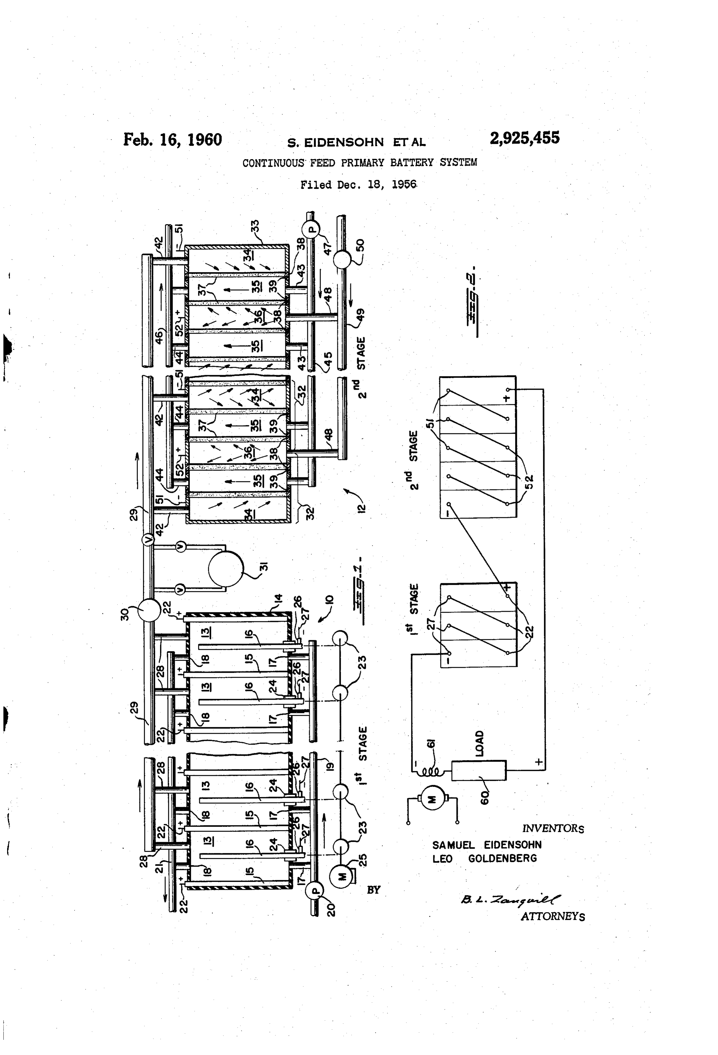
Application December 18, 1956, Serial No. 629,199 Fig. 1 is an overall plan view, partially in diagram 0 matic cross section, of the two stage primary battery sys 11 Claims. (C. 136-86) tem of the invention.
(Granted under Title 35, U.S. Code (1952), SeC. 266) Fig. 2 is a schematic diagram showing a series con nection between the two stages, whereby their electrical outputs are combined. -
Referring now to the drawings, wherein like reference
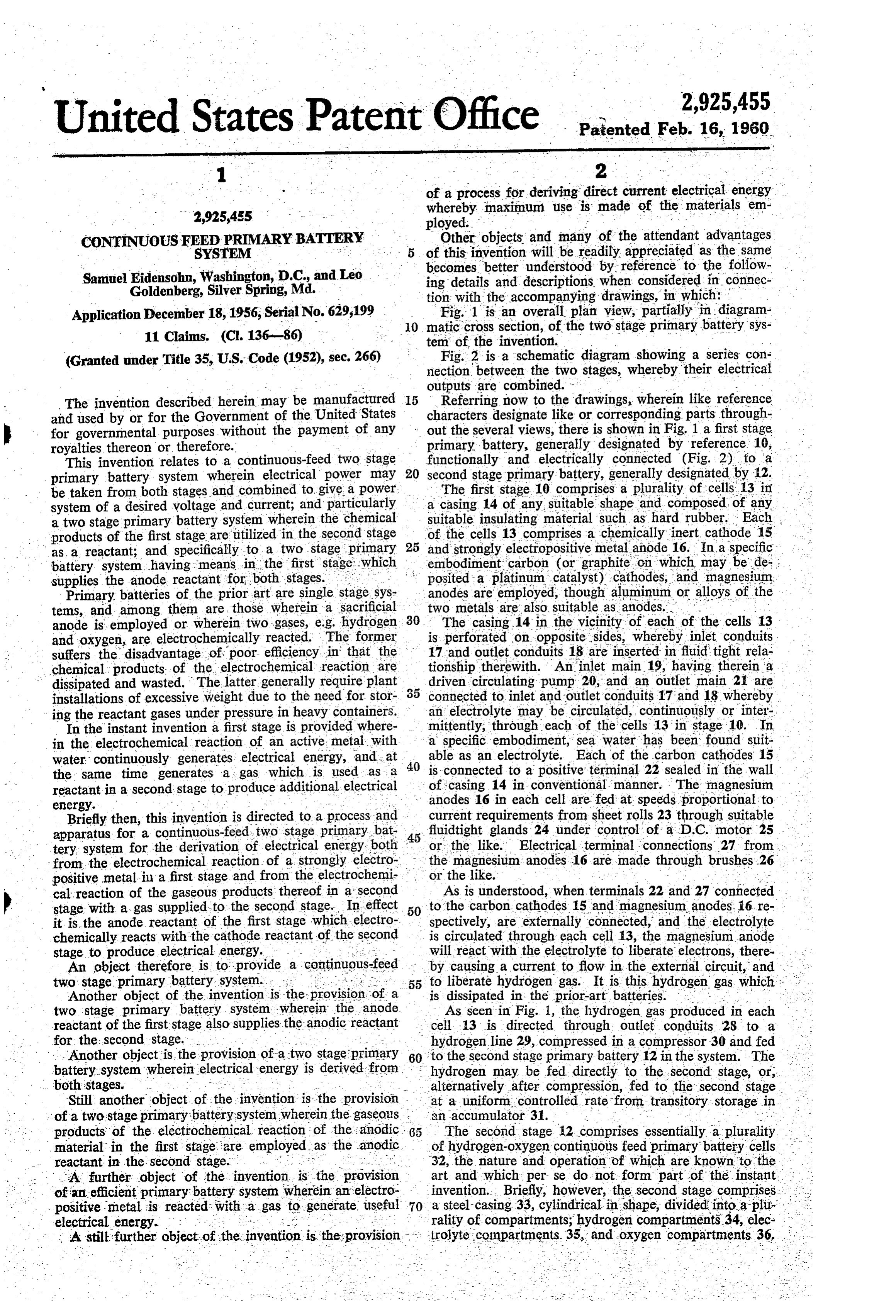
The invention described herein may be manufactured characters and used by or for the Government of the United States designate like or corresponding parts through for governmental purposes without the payment of any " out the several views, there is shown in Fig. 1 a first stage royalties thereon or therefore. primary battery, generally designated by reference. 10, This invention relates to a continuous-feed two stage functionally and electrically connected (Fig. 2) to a primary battery system wherein electrical power may 20 second stage primary battery, generally designated by 2. be taken from both stages and combined to give a power The first stage 10 comprises a plurality of ce -- system of a desired voltage and current; and particularly a casing 14 of any -- - - - - - - - a two stage primary battery system wherein the chemical suitable insulating material such as hard rubber. Each products of the first stage are utilized in the second stage of the cells 13 comprises a chemically inert cathode 15 as a reactant; and specifically to a two stage primary 25 and strongly electropositive metal anode 16. In a specific battery system...having means in the first stage-whi hich embodiment carbon (or graphite on which may be des: supplies the anode reactant for both stages. posited a platinum catalyst) cathodes, and magnesium. Primary batteries of the prior art are single stage sys anodes are employed, though aluminum or alloys of the tems, and among them are those wherein a sacrificial two metals are also suitable as anodes.
anode is employed or wherein two gases, e.g. hydrogen 30 The casing 14 in the vicinity of each of the cells 13 and oxygen, are electrochemically reacted. The former is perforated on opposite sides, whereby inlet conduits. suffers the disadvantage of poor efficiency in that the 17 and outlet conduits 18 are inserted in fluid tight rela chemical products of the electrochemical reaction are tionship therewith. An inlet main 19, having therein a dissipated and wasted. The latter-generally require plant driven circulating pump 20, and an outlet main 21 are installations of excessive weight due to the need for stor 35 connected to inlet and outlet conduits 17 and 18 whereby ing the reactant gases under pressure in heavy containers. an electrolyte may be circulated, continuously or inter In the instant invention a first stage is provided where mittently, through each of the cells 13 in stage 10. In in the electrochemical reaction of an active metal, with aablespecific embodiment, sea water has been found suit water continuously generates electrical energy, and at 40 as an electrolyte. Each of the carbon cathodes 15 the same time generates a gas which is used as a isof connected to a positive terminal 22 sealed in the wall casing 14 in conventional manner. The magnesium reactant in a second stage to produce additional electrical energy. - - - anodes 16 in each cell are fed at speeds proportional to
Briefly then, this invention is directed to a process and . current requirements from sheet rolls 23 through suitable apparatus for a continuous-feed two stage primary bat fluidtight glands 24 under control of a D.C. motor 25 tery system for the derivation of electrical energy both 45 or the like. Electrical terminal connections 27 from . from the electrochemical reaction of a strongly electro the magnesium anodes 16 are made through brushes. 26. . . . positive metal in a first stage and from the electrochemi or the like. .. . .. . . . . . . .. . cal reaction of the gaseous products thereof in a second As is understood, when terminals 22 and 27 connected stage with a gas supplied to the second stage. In effect 50 to the carbon cathodes 15 and magnesium anodes 16 re it is the anode reactant of the first stage which electro spectively, are externally connected, and the electrolyte chemically reacts with the cathode reactant of the second is circulated through each cell 13, the magnesium anode stage to produce electrical energy. . . . . . . . . . . . . . will react with the electrolyte to liberate electrons, there An object therefore is to provide a continuous-feed by causing a current to flow in the external circuit, and two stage primary battery system. . . .
Another object of the invention is the prow . . . -- . . " to liberate hydrogen gas. It is this hydrogen gas which - of a 55 is dissipated in the prior-art batteries.
two stage primary battery system wherein the anode As seen in Fig. 1, the hydrogen gas produced in each reactant of the first stage also supplies the anodic reactant cell 13 is directed through outlet conduits 28 to a
Another object is the provision of a two stage primary 60 to .. . . . hydrogen line 29, compressed in a compressor 30 and fed to the second stage primary battery 12 in the system. The - battery system wherein electrical energy is derived from hydrogen may be fed directly to the second stage, or, both stages. alternatively after compression, fed to the second stage still another object of the invention is the provision
I of a two-stage primary battery system wherein the gaseous at a uniform controlled rate from-transitory storage in .
an accumulator 31. - - ... . . . . . .. . .
products of the electrochemical reaction of the anodic The second stage 12 comprises essentially a plurality material in the first stage are employed as the anodic of hydrogen-oxygen continuous feed primary battery cells
A further object of the invention is the provision . . . . . . ." 32, the nature and operation of which are known to the art and which per se do not form part of the instant.
of an efficient primary battery system wherein an electro invention. Briefly, however, the second stage comprises. . . . . positive metal is reacted with a gas to generate useful 70 a steel-casing 33, cylindrical in shape, divided into a plu electrical energy. . . . . . . . . . .. . . . . . . . . . . . . rality of compartments; hydrogen compartments.34, elec A still further object of the invention is the provision. s strolyte compartments. 35, and oxygen compartments 36, ... . .
Page 3
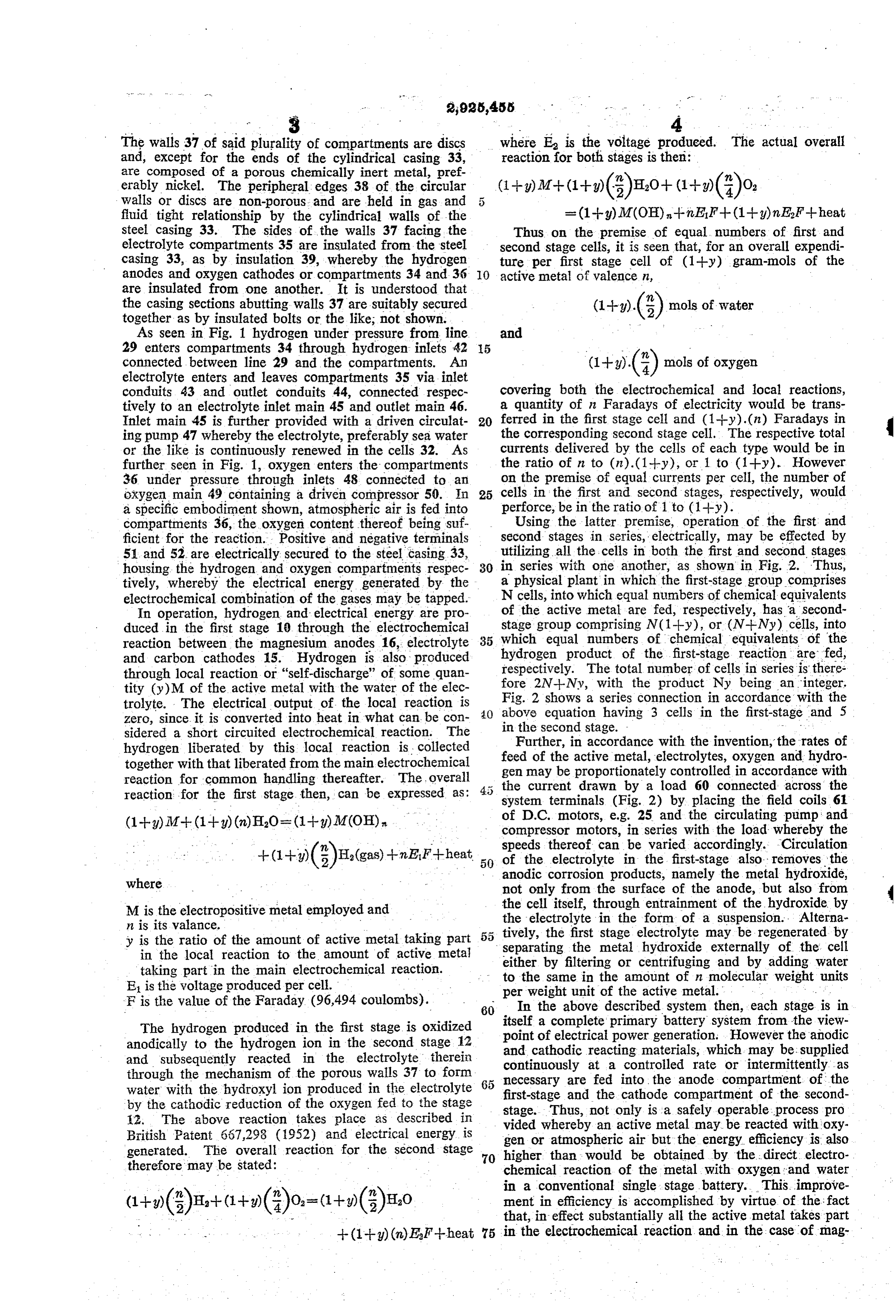
The walls 37 of said plurality of compartments are discs and, except for the ends of the cylindrical casing 33, where E is the voltage produced. The actual overall reaction for both stages is then:
are composed of a porous chemically inert metal, pref erably nickel. The peripheral edges 38 of the circular
Walls or discs are non-porous and are held in gas and fluid tight relationship by the cylindrical walls of the = (1--g)M(OH)--in EF--(1-y) nEF--heat steel casing 33. The sides of the walls 37 facing the Thus on the premise of equal numbers of first and electrolyte compartments 35 are insulated from the steel second stage cells, it is seen that, for an overall expendi casing 33, as by insulation 39, whereby the hydrogen ture per first stage cell of (1-y) gram-mols of the anodes and oxygen cathodes or compartments 34 and 36 O active metal of valence n, are insulated from one another. It is understood that the casing sections abutting walls 37 are suitably secured (i. +).() mols of water together as by insulated bolts or the like, not shown.
As seen in Fig. 1 hydrogen under pressure from line and 29 enters compartments 34 through hydrogen inlets 42 5 connected between line 29 and the compartments. An (1+d).() mols of oxygen electrolyte enters and leaves compartments 35 via inlet conduits 43 and outlet conduits 44, connected respec covering both the electrochemical and local reactions, tively to an electrolyte inlet main 45 and outlet main 46. a quantity of in Faradays of electricity would be trans Inlet main 45 is further provided with a driven circulat 20 ferred in the first stage cell and (1-y). (n) Faradays in the corresponding second stage cell. The respective total ing pump 47 whereby the electrolyte, preferably sea water or the like is continuously renewed in the cells 32. As currents delivered by the cells of each type would be in further seen in Fig. 1, oxygen enters the compartments the ratio of n to (n). (1-y), or 1 to (1-y). However 36 under pressure through inlets 48 connected to an on the premise of equal currents per cell, the number of oxygen main 49 containing a driven compressor 50. In 25 cells in the first and second stages, respectively, would a specific embodiment shown, atmospheric air is fed into perforce, be in the ratio of 1 to (1-y). Using the latter premise, operation of the first and compartments 36, the oxygen content thereof being suf ficient for the reaction. Positive and negative terminals second stages in series, electrically, may be effected by 51 and 52 are electrically secured to the steel casing 33, 30 inutilizing all the cells in both the first and second stages series with one another, as shown in Fig. 2. Thus, housing the hydrogen and oxygen compartments respec a physical plant in which the first-stage group comprises tively, whereby the electrical energy generated by the electrochemical combination of the gases may be tapped. of the activewhich
N cells, into equal numbers of chemical equivalents metal are fed, respectively, has a second
In operation, hydrogen and electrical energy are pro stage group comprising N(1-y), or (N--Ny) cells, into duced in the first stage 10 through the electrochemical 35 which reaction between the magnesium anodes 16, electrolyte equal numbers of chemical equivalents of the and carbon cathodes 15. Hydrogen is also produced hydrogen product of the first-stage reaction are fed, respectively. The total number of cells in series is there through local reaction or "self-discharge' of some quan fore 2N--Ny, with the product Ny being an integer. tity (y)M of the active metal with the water of the elec
Fig.2 shows a series connection in accordance with the trolyte. The electrical output of the local reaction is 2.0 above zero, since it is converted into heat in what can be con equation having 3 cells in the first-stage and 5 sidered a short circuited electrochemical reaction. The in the second stage. -
Further, in hydrogen liberated by this local reaction is collected feed of the active accordance with the invention, the rates of together with that liberated from the main electrochemical metal, electrolytes, oxygen and hydro reaction for common handling thereafter. The overall gen may be proportionately controlled in accordance with reaction for the first stage, then, can be expressed as: the current drawn by a load 60 connected across the system terminals (Fig. 2) by placing the field coils 61 of D.C. motors, e.g. 25 and the circulating pump; and compressor motors, in series with the load whereby the
where +(1+)(i)H, (gas)+n E.F+heat speeds thereof can be varied accordingly. Circulation of the electrolyte in the first-stage also removes the
anodic corrosion products, namely the metal hydroxide, not only from the surface of the anode, but also from
M is the electropositive metal employed and the cell itself, through entrainment of the hydroxide by n is its valance. the electrolyte in the form of a suspension. Alterna 55 tively, y is the ratio of the amount of active metal taking part separatingthe first stage electrolyte may be regenerated by in the local reaction to the amount of active metal the metal hydroxide externally of the cell taking part in the main electrochemical reaction. either by filtering or centrifuging and by adding water E is the voltage produced per cell. to the same in the amount of n molecular weight units per weight unit of the active metal. . . . ..
F is the value of the Faraday (96,494 coulombs). In the above described system then, each stage is in 60 itself
The hydrogen produced in the first stage is oxidized point of a complete primary battery system from the view anodically to the hydrogen ion in the second stage 12 and cathodic electrical power generation. However the anodic and subsequently reacted in the electrolyte therein continuously atreacting materials, which may be supplied through the mechanism of the porous walls 37 to form necessary are feda into controlled rate or intermittently as the anode compartment of the water with the hydroxyl ion produced in the electrolyte first-stage and the cathode by the cathodic reduction of the oxygen fed to the stage stage. Thus, not only is a compartment of the second safely operable process pro 2. The above reaction takes place as described in vided whereby an active metal may be reacted withoxy British Patent 667,298 (1952) and electrical energy is gen or atmospheric air but the energy efficiency is also generated. The overall reaction for the second stage 70 higher than would be obtained by the direct electro therefore may be stated: chemical reaction of the metal with oxygen and water in a conventional single stage battery. This improve (1+y)(3)H,+(1+) ()0-(+) (i)HO ment in efficiency is accomplished by virtue of the fact that, in effect substantially all the active metal takes part . . . +(1+) ()EF-heat 75 in the electrochemical reaction, and in the case of mag
Page 4
5. - 6.
hydrogen is liberated, and a second stage of the type nesium the improvement in material utilization can be wherein electrical energy is generated by electrochemical as high as 66% over alternate methods. .. . reaction of two gases, means for conveying to the second Obviously many modifications and variations of the stage hydrogen liberated in the first stage for electro present invention are possible in the light of the above chemical teachings. It is therefore to be understood that within means forreaction 5 with oxygen in such second stage, and tapping electrical energy from each of the the scope of the appended claims the invention may be two stages. .. .. .: practiced otherwise than as specifically described. - 6. A two stage primary battery system as set forth in
1. A method of generating useful electrical energy in claim 5 wherein the first stage includes a first casing a two stage primary battery system which comprises, re 0 containing an electrolyte, an anode and a cathode, means for supplying a hydrogen-containing electrolyte to said acting a strongly electropositive sacrifical metal anode with an aqueous electrolyte in the presence of a chemical casing and means for supplying to the casing an electro positive metal capable of liberating hydrogen when ly inert cathode in a first stage of the system, to thereby immersed generate electrical energy and liberate a reactant gas, 5 ing means inconveys the electrolyte, and wherein the gas convey conveying the hydrogen gas from the first stage of the the second stage ofliberated hydrogen from the casing to the system.
system to a second stage thereof, electrochemically re 7. A two stage primary battery system as set forth in acting the hydrogen gas from the first stage, as the anode claim 6 wherein the second stage includes a second casing with oxygen as the cathode in an electrolyte in the second stage to thereby generate electrical energy in the second 20 having from means therein for receiving hydrogen conveyed the first stage, means for supplying an electrolyte stage, and tapping electrical energy from each of the : to said second
casing, and means for supplying an oxygen 2. A method of generating electrical energy in a two containing gas to said second casing. - 8. A two stage primary battery system as set forth in stage primary battery system which comprises, continu claim 7 wherein the means for tapping electrical energy ously feeding a sacrificial metal as an anode into an aqueous electrolyte in the presence of an inert cathode 25 from each of the two stages includes terminals connected for series flow of electrical energy and a load connected in a first stage of the system to thereby generate electrical across such terminals.
energy and liberate hydrogen in such first stage, convey ing the hydrogen from the first stage to a second stage 9. A two stage primary battery system as set forth of the system for use as an anode therein, electrochemi 30 in claim 8 which includes means operated responsive to the load connected across the terminals of the system for cally combining the hydrogen with a oxygen in an elec trolyte in the second stage to thereby generate electrical proportionality controlling the supply of electrolyte and energy in said second stage, and tapping electrical energy the first to the secondtostage, electropositive metal the first stage, hydrogen gas from and electrolyte and oxygen from each of the stages.
3. A method of generating electrical energy in a two :35 containing gas to the second stage. 10. A method of generating electrical energy in a two
stage primary battery system which comprises continu . . stage primary battery system which comprises, continu ously feeding a sheet of magnesium as an anode into sea.
water as an electrolyte in the presence of carbon as a ously feeding a sacrificial metal as an anode into an aqueous electrolyte in the presence of an inert cathode cathode in a first stage of the system to thereby gen erate electrical energy and liberate hydrogen gas as a 40 in a first stage of the system to thereby generate elec trical energy and liberate hydrogen in said first stage, by-product of the electrochemical reaction, conveying the conveying the reactant gas from said first stage to a hydrogen gas from the first stage to a second stage of second stage of the system for use as an anode therein, the system for use as an anode therein, feeding an oxygen and electrochemically containing gas as a cathode and sea water as an elec combining the hydrogen with oxy trolyte into the second stage of the system to thereby 45. gen in an electrolyte in the second stage, to thereby gen generate electrical energy in such second stage, and erate 11. electrical energy
A two stage in saidbattery primary secondsystem stage. according to tapping electrical current from each of the two stages claim 1, but further characterized by means for removing
the product of the reaction of said metal anode and said 4. A method of generating electrical current as set electrolyte forth in claim 3 wherein the electrical energy is tapped from said first stage of said system whereby from the first and second stages in series electrically, 50 the efficiency of said reaction may not be reduced. and wherein the rates of feed of the sheet magnesium References Cited in the file of this patent anode and the sea water electrolyte into the first stage, hydrogen gas from the first to the second stage, and UNITED STATES PATENTS - oxygen gas and sea water electrolyte into the second 55 Jacobson --------------- May 2, 1939. stage are proportionately controlled in accordance with 2,156,693 current drawn from the system by a load connected 2,570,543 Gorin ------------------ Oct. 9, 1951 across terminals thereof. - 2,590,584 Taylor ---------------- Mar. 25, 1952 5. A two stage primary battery system comprising in 2,716,670 Bacon ---------------- Aug. 30, 1955 combination means forming a first stage of the electro 60 FOREIGN PATENTS positive metal reactant type by reaction of the electro 8,906 Great Britain ------------------ 1896 - positive metal against an inert cathode in an aqueous 600,745 Great Britain ---------- Apr. 16, 1948 electrolyte wherein electrical energy is generated and
Provenance
- Collection
- Cited prior art
- Original PDF
- patentimages.storage.googleapis.com →
- Filed
- 1956-12-18
- Pages
- 4
- Method
- pdftotext (the PDF's own text layer) + pdftoppm 300dpi page scans
- Source
- Google Patents bibliographic record
- Granted
- 1960-02-16
- Inventors
- Eidensohn Samuel; Goldenberg Leo
- Transcribed from
- patentimages.storage.googleapis.com →