patent · US3218195
Electricity generating cell
16 November 1965
Page 1
Drawing sheet — no readable text.
Page 2
United States Patent Office Patented Nov. 16, 1965
a cathode compartment 22. While the anode and cathode 3,218,195 compartments are shown roughly equal in size, their ELECTRICITY GENERATING CELL relative dimensions may vary considerably in practice. Sidney A. Corren, 163 Cherry St., Katonah, N.Y. A well 24 formed between rib 16 and the sidewalls of Filed Aug. 27, 1964, Ser. No. 392,405 the vessel constitutes a receptacle for confining a liquid 11. Claims. (CI. 136-86) anode. A similar well 26 is provided in the cathode compartment to receive a liquid cathode. Preferably ves
This application is a continuation-in-part of copending sel 10 is provided with a cover 28.
application, Ser. No. 84,535 filed Jan. 24, 1960. In the cell shown, the anode consists preferably of a This invention relates to methods and apparatus for 0. layer 25 of particles of intermetallic compounds of alu producing electricity either intermittently, upon demand, minum more specifically described hereinafter, Said par or continuously, and it relates particularly to systems ticles being at least superficially amalgamated and floating wherein the electricity is produced as a result of chem on a pool of mercury 45 which serves to electrically con ical reactions effected at electrodes. nect the particles with an electrically conductive bar Systems wherein a fossil fuel is caused to combine 46 which may be made of graphite or of a metal not with oxygen in an electrochemical reaction producing soluble in mercury. Conductive bar 46 may be sealed electricity constitute "fuel cells' in the classical sense. into and extend both inward and outward from the base Present day usage has extended the term to encompass 12 or sidewall 14 (as shown) of the vessel in Such a po not only electric generating systems in which carbon is sition that its inward extension lies within mercury pool caused to combine with oxygen but also systems in which 20 45. Alternatively bar 46 may extend downward through hydrogen is caused to combine with OXygen or even any cover 28 extending through the electrolyte substantially cell in which electricity is produced by an oxidation filling anode compartment 20 and particularly layer 25 reduction reaction in which the oxidant is continuously and terminating in mercury pool 45. When inserted in supplied at one electrode while the reductant is supplied this fashion, it is preferable that bar 46 be protected by at another electrode and the resultant products are con 25 an insulator sheath such as a glass tube from which elec tinuously removed from the cell. trolyte is sealed. Bar 46 serves as the external anode One object of this invention is to provide a fuel cell connection for the cell. The cell reaction will result in which is capable of automatic attention-free operation the release of mercury from amalgamated anode mate for long periods and which is characterized by a simplicity rial as the latter is used up. This excess mercury may of construction, high output and relatively long life with 30 be drawn off through a convenient drain in the bottom of no danger of escaping inflammable or explosive gasses. the vessel and may be reused.
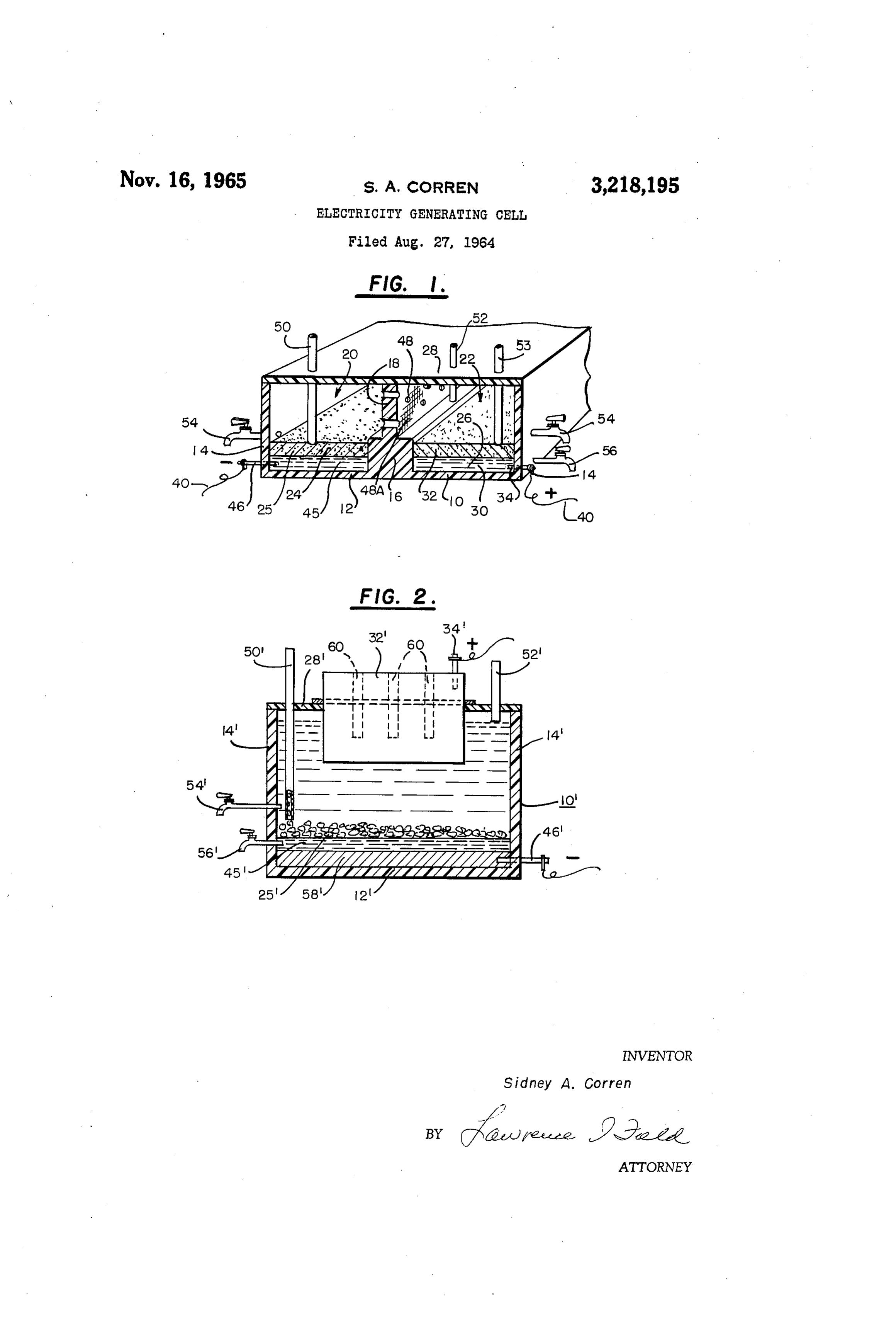
Another object is to provide a fuel cell which is simple In the cell shown in FIGURE 1, the cathode is pref. in construction and which operates silently, at low tem erably generally similar in construction to the anode ex peratures and at atmospheric pressure and with essentially cept that the cathode consists of a body of mercury 30 no heat evolution and no danger of explosion. on which there floats a thin layer 32 of a mixture con A particular object is to provide an anode electrode sisting of powdered carbon such as graphite or acetylene system which is particularly advantageous for use in bat black and a metallic oxide such as HgC), PbO or MnO2. tery cells with various counter-electrodes. The thickness of layers 30 and 32 has been exaggerated A general object of this invention is to provide an alu for purposes of illustration in FIGURE 1. An electri minum containing anode which is stable in a battery cell 40 cally conductive member 34 is secured through any wall system at rest but capable of reaction when demand is of the cathode compartment so as to remain in contact put upon the cell. with the liquid cathode. Member 34 is analogous in These and other objects are achieved by the battery structure to bar 46. Members 34 and 46 are connected cell of the present invention, preferred species of which to electrical leads shown schematically at 40. are described in the description which follows and in the 45 The physical barrier 18 which extends the electrode accompanying drawings in which the several figures are compartment separator the full height of the cell is not schematic representations of two types of fuel cells which essential to the operation of the cell, but is desirable in have been operated according to the invention and in that it prevents transfer of active electrode material from which one electrode compartment to the other, especially if the FIGURE 1 is a view, partly in section showing one cell is moved. Barrier 18 is preferably a sheet of the form of fuel cell according to the invention; same synthetic plastic as that used for the vessel 10 and FIGURE 2 is a view of a modified cell in which a is provided with large perforations 48 so that electrolyte porous carbon air electrode is utilized. and ions can flow freely between the anode and cathode In general the essential elements of the fuel cells shown compartments.
in the drawings comprise: 55 Barrier 18 is preferably covered with a woven cloth (1) An anode; 48A of nylon or other standard battery separator mate (2) A cathode; rials whose pores are sufficiently small to prevent the pas (3) An electrolyte; Sage of solid particles between the anode and cathode (4) Means for feeding the reactants into the cell and compartments.
for removing the products of the reaction from the cell; 60 It should be noted that barrier 18 is not essential, pel and leting (described below) being preferred as the means to (5) Various auxiliary means to facilitate operation avoid the loss in efficiency which occurs when portions of of the cell. the cathode (layer 32) transfer to the anode side as a re In the embodiment shown schematically in section in sult of turbulence. Barrier 18 is an added precaution to FIGURE 1, the cell consists of a vessel 10 formed of 65 minimize material transfer between compartments 20 plastic, glass or other suitably inert electrically insulating and 22.
material, polymethylmethacrylate being one such suitable Operation of the cell has been found to be improved by material. Vessel 10 comprises a base 12 and upstanding mixing the carbon and mercuric oxide, pelleting the mix side walls 14. Extending transversely across the base ture and then charging the pellets into the cathode com and rising upwardly from the base is a rib or ridge 16 70 partment 22. By this means the carbon or oxide do not on which a baffle 18 is supported, so as to divide vessel clog the pores or pass through them and into the anode 10 into two compartments: an anode compartment 20 and compartment.
Page 3
A desirable anode material would be aluminum because then mixed vigorously with the pool of mercury. The its reaction can potentially release a comparatively large particles were at least superficially amalgamated by the number of watt hours per pound of aluminum. However, mercury to form a slightly adherent mass which floated on because of its relatively high chemical activity, it is virtual the excess mercury. The floating mass was removed and ly impossible to use it in a cell in contact with an aqueous was then fed into tube 50 extending onto the layer of mer solution and especially not in contact with an alkaline cury in well 24 of the cell shown in FIGURE 1, wherein solution. Pure aluminum will react with water to yield it constituted the replenishment of the intermetallic anode hydrogen except when it is covered with a protective layer material. In the cell the pasty amalgam floats on the of oxide in which case it becomes unreactive for all pur mercury in well 24. It is also possible but not preferred poses. When it is used in the form of an amalgam it is O to form the pasty layer directly on a pool of mercury pres still extremely reactive and will generate hydrogen even ent in the cell, by adding intermetallic material from time when in contact with distilled water. to time as needed.
Various alloys have been tried but all of them react With the system FeAli, Hg/NaOH, H2O/HgO, C, Hg with the usual electrolytes to a greater or lesser degree. a cell similar to that shown in FIGURE 1 was run for Inhibitors in the electrolyte may slow down the reaction 15 months through a load of 51.7 ohms at 0.96 volt out but do not prevent it. They usually form protective coat put, producing 177 watt hours. ings on the aluminum which cause the cell to respond slow The relative size of compartments 20 and 22 should be ly to a demand for current. Such that each electrode operates at its maximum current In contradistinction I have found that certain combina density. This will depend to some extent on the shape, tions of iron and aluminum prepared by melting together 20 size and composition of the electrode particles. the component metals and crushing the cooled product Suitable means shown schematically as tubes 50 and 53 behave like metals lower in the electromotive series than extend into vessel 10 for replenishing the FeAl and mer aluminum. They do not react with the electrolyte of this curic oxide from time to time, as they are consumed, and invention to generate appreciable amounts of hydrogen also outlets 54, 56 for removing the spent electrolyte and and therefore large excesses of material can be maintained 25 mercury and graphite formed as a result of cell operation. in the system. The system can therefore be operated for Inlet 52 is used for replenishing the electrolyte. long periods without movement or sound from auxiliary In the system of this example, the iron remained as a equipment and a reservoir of fuel to respond to surges of residue of fine powder suspended in the electrolyte which power demand can be maintained. The cell can stand was removed readily with the waste electrolyte through with the anode material in contact with caustic or other 30 suitable outlets.
suitable electrolyte with substantially no reaction when Electrolyte: A 25% sodium hydroxide solution was no current is being drawn from the cell but reaction will used but any equivalent alkaline solution might have been start and current will be generated as soon as a load is used. The concentration is not critical. What is essen put upon the cell. tial is a relatively strong source of alkali metal and The preferred compositions correspond to compounds 35 hydroxyl ions. Potassium hydroxide and sodium carbon which appear on the phase diagram for iron and aluminum ate are useable alternatives. For ease of continuous and it is presumed that the materials actually occur in operation, the waste electrolyte containing sodium alumi the form of indicated compounds such as FeAl2. Mix nate was drawn off and replaced with fresh electrolyte. tures of the compounds are similarly useable. The com It is possible however by control of the pH to precipitate pound FeAl corresponding to a melt containing 51% Fe. the aluminum as the hydrate and regenerate the sodium
and 49% Al has been found to be particularly advan hydroxide.
tageous. It has a desirably high aluminum content. Cathode: The cathode of this equipment was made by Possessing the above described advantages of anode sta mixing mercuric oxide powder as purchased from Fisher bility in contact with electrolyte. Cells using partially Scientific Company with 10% powdered graphite and amalgamated FeAl2 can be run intermittently and with 45 compacting into pellets. The pellets made a very con varying electrical output independent of the feed rate of venient cathode when floated on a bed of mercury. The anode material, provided only that sufficient material is System is not dependent upon using this material as cath present to support the reaction. The FeAla has the further ode but will operate effectively with other depolarizers advantage that its particles can be readily partially amal or fuel cell cathodes such as lead oxide, silver oxide and gamated and that they will then float on the surface of 50 air or oxygen porous electrodes. With an oxygen elec the liquid mercury as a porous mass with a large active trode the reaction appears to be anode area. The particles do not completely dissolve in the mercury in which event the anode area would be re duced to the area of the geometric plane. The area avail able for anode reaction and the maximum output rate of 55 The open circuit voltage of this system is 1.1 volts. the cell would be therefore materially reduced. It was maintained on continuous operation for 3 years The above advantages are in apparent distinction from discharging through 52 ohms with an operating voltage various other aluminum alloys, usually without involve between 0.9 and 1.0 volt. Operation was very simple ment of any major part of the aluminum in compound because excess ingredients could be added. Thus from formation, which are reactive with alkaline electrolytes. 60 time to time FeAl 25% NaOH electrolyte and HgC), For purposes of illustration, one manner of using FeAl C pellets were added. Waste electrolyte with fine iron as the anode material will now be described in some powder and mercury were drawn off.
detail. For example during another twenty month period the Since FeAll contains only 49%. Al, the 50-50 alloy pur cell was discharged through a load of 50 ohms at an chased as an article of commerce, actually contains a 65 average of 0.96 volt. Fed in were 1307 grams of 50% slight excess of aluminum. The FeAla was ground to iron aluminum powder and 751 grams of the mercuric about 60 mesh (Tyler standard) particle size by conven oxide-10% graphite mix. 25% sodium hydroxide was tional apparatus. A pool of mercury was charged into a fed in at an approximate rate of 75 cc. per day. This cell clean glass beaker and a thin layer of a 25% aqueous ran with no attention over weekends and holidays. solution of NaOH was poured onto the pool of mercury. 70 FIGURE 2 illustrates a cell utilizing the same anode The particles of FeAl were dropped into the layer of materials and electrolyte as those used with the cell of aqueous caustic and any superficial oxide present on the FiGURE 1, except that the cathode is a porous carbon particles was removed by the contact with the caustic as electrode.
the solid particles of the intermetallic compound settled The cell shown in FIGURE 2 comprises a vessel 10' by gravity into the pool of mercury. The particles were 75 having a base 12, sidewalls 14 and a cover 28' all of
Page 4
polymethylmethacrylate or other suitable chemically 8. The battery cell of claim 1 wherein the cell includes inert material. at least one porous carbon cathode through which air Resting on the bottom 12' is a graphite slab 58 elec may be introduced into the cell to supply the reducible trically connected to bar 46' through the wall of vessel cathode material.
10'. A pool of mercury 45' rests on the slab and sup 5 9. The battery cell of claim 2 wherein the cell includes ports a layer of superficially amalgamated particles of at least one porous carbon cathode through which air intermetallic compound 25. may be introduced into the cell to supply the reducible Supported by cover 28’ is an air cathode 32' which is cathode material.
a massive piece of porous carbon having a plurality of 10. A fuel cell comprising a vessel formed of material dead ended holes 60 bored into its upper outer surface, O which is electrically insulating and which is chemically external of the cell. The holes are provided for the inert towards the content of the vessel; means including purpose of increasing the area through which atmos liquid mercury for effecting the introduction into said pheric O or air can diffuse to the active electrode surface. vessel of an oxidizable condensed phase anode material This type of electrode is well known, per se, being consisting of superficially amalgamated solid particles described in Vinal's text "Primary Batteries' on pages 217 5 of intermetallic compounds of aluminum and iron; and and 218 and is commercially available in various sizes means including liquid mercury for introducing a re and shapes. ducible cathode material consisting of powdered carbo The cover also supports conduit means 50' and 52 naceous material and a reducible metal oxide into said for the admission of fresh particles of amalgamated metal vessel; barrier means for confining the anode material and fresh electrolyte respectively. 20 within the confines of an anode region in said vessel and A terminal 34' affords an electrical connection to the in electrical contact with an anode electrode and for air cathode. confining the cathode material within the confines of a Outlets 54 and 56' are provided for the removal of cathode region in said vessel and in electrical contact waste electrolyte and the suspended iron particles therein with a cathode electrode; means for maintaining the and for the removal of excess mercury, so as to avoid 25 volume remaining in said vessel, in addition to that an undesirable increase in the size of the pool of mercury. occupied by the anode and cathode materials, substan The remainder of vessel 10 contains a suitable alkaline tially filled with an aqueous electrolyte electrically con electrolyte of the kind previously described. necting said anode and said cathode; means for with In one test utilizing the cell of FIGURE 2 with an drawing from said vessel, the products of an electro anode consisting of particles of FeAla between /8 inch 30 chemical reaction wherein the anode material is oxidized and 20 mesh, superficially amalgamated, the following and the cathode material is reduced in said vessel; and operating voltages were obtained: leads electrically connected to said anode and said cathode Load: Volts whereby the electrical output of said cell may be re Open circuit --------------------------- 1.10 covered and utilized.
43 ohms ------------------------------- 1.00 11. A fuel cell comprising a vessel formed of material 23.1 ---------------------------------- 0.96 which is electrically insulating and which is chemically 10.3 ---------------------------------- 0.92 inert towards the content of the vessel; means including 5.0 ----------------------------------- 0.84 liquid mercury for effecting the introduction into said 1.1 ----------------------------------- 0.59 40 vessel of an oxidizable condensed phase anode material consisting of Superficially amalgamated solid particles of
I claim: intermetallic compounds of aluminum and iron; barrier 1. In an electricity generating cell wherein an oxidiz means for confining the anode material within the con able condensed phase anode material and a reducible fines of an anode region in said vessel and in electrical cathode material react in an oxidation-reduction reaction contact with an anode electrode; at least one porous with consequent production of electricity, the improve 45 carbon cathode serving as means for introducing air into ment which comprises providing as the principal con the cell to supply reducible cathode material; means for stituent of the oxidizable condensed phase anode mate maintaining the volume remaining in said vessel, in addi rial, Superficially amalgamated particles of an intermetal tion to that occupied by the anode and cathode materials, lic compound of aluminum and iron represented by the substantially filled with an aqueous electrolyte electrically formula FeAl2. 50 connecting Said anode and said cathode; means for with 2. The electricity generating cell of claim 1 wherein drawing from said vessel, the products of an electro the oxidizable anode material consists of superficially chemical reaction wherein the anode material is oxidized amalgamated particles of FeAl. and the cathode material is reduced in said vessel; and 3. The fuel cell of claim 1 wherein the reducible cath leads electrically connected to said anode and said cath ode material is a mixture of powdered carbonaceous ode whereby the electrical output of said cell may be material and a reducible metal oxide. recovered and utilized.
4. The electricity generating cell of claim 3 wherein the powdered carbonaceous material and metal oxide References Cited by the Examiner comprising the reducible cathode material is in the form 60 UNITED STATES PATENTS of pellets of a mixture of the oxide and carbonaceous 553,719 1/1896 Olan ---------------- 136-83 material.
5. The electricity generating cell of claim 3 wherein 2,275,281 3/1942 Berl -------------- 136-86.2 the metal oxide is selected from the group consisting of 2,542,575 2/1951 Ruben ------------- 136-107 HgO, PbO and MnO2. 2,646,458 7/1953 Walz. -------------- 136-100 6. The electricity generating cell of claim 2 wherein 65 3,057,946
the reducible cathode material is a mixture of powdered carbonaceous material and a reducible metal oxide.
7. The electricity generating cell of claim 6 wherein WINSTON A. DOUGLAS, Primary Examiner.
the metal oxide is selected from the group consisting of JOHN H. MACK, Examiner.
HgO, PbO and MnO2. 70
Provenance
- Collection
- Cited prior art
- Original PDF
- patentimages.storage.googleapis.com →
- Pages
- 4
- Method
- pdftotext (the PDF's own text layer) + pdftoppm 300dpi page scans
- Source
- Google Patents bibliographic record
- Granted
- 1965-11-16
- Transcribed from
- patentimages.storage.googleapis.com →