patent · US3892653
Hydrogen generator
1 July 1975
Page 1 — bibliographic record
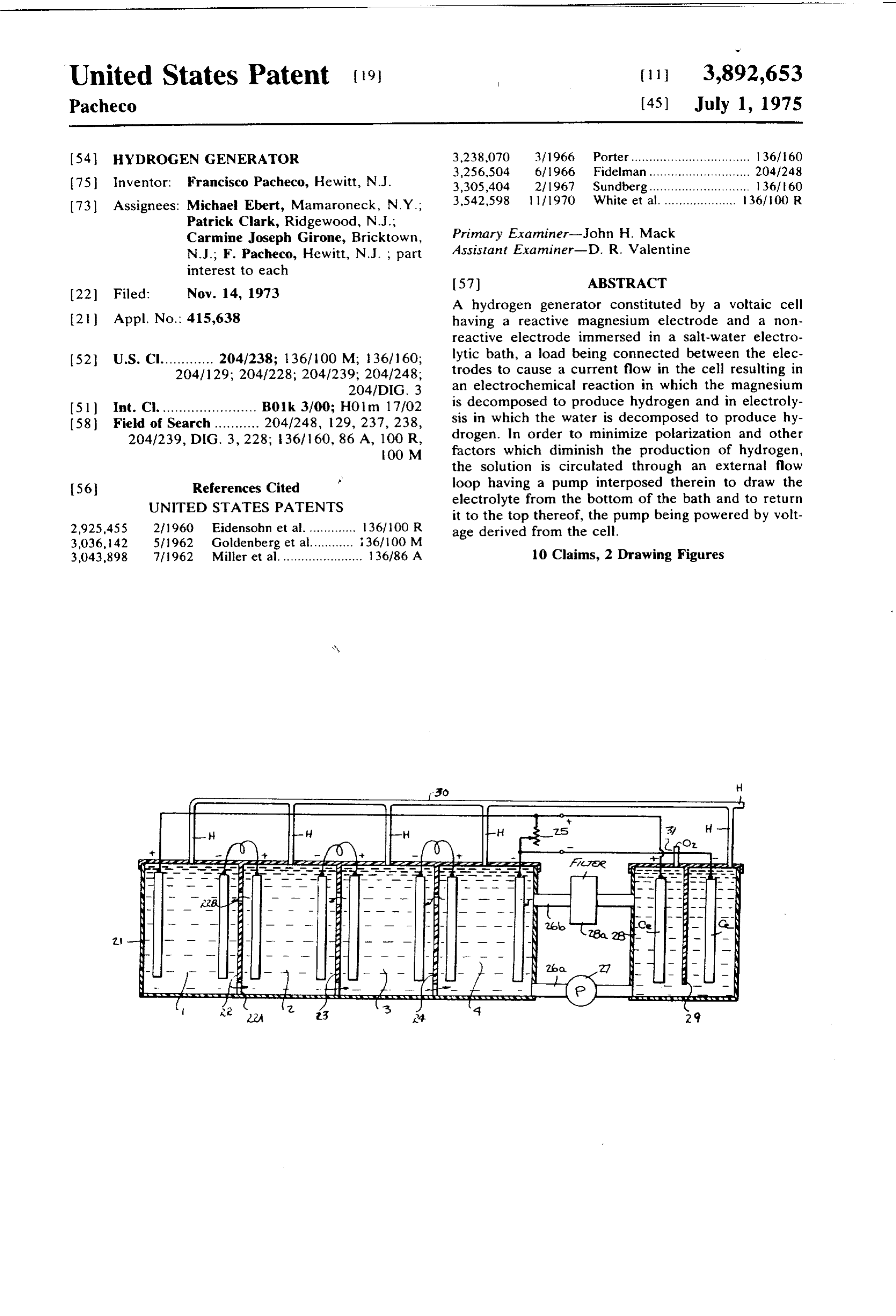
United States Patent 19 (11 3,892,653 Pacheco (45) July 1, 1975 - - - - T 54 HYDROGEN GENERATOR 3,238,070 3/1966 Porter................................. 136160 is inventor Francisco Pacheco, Hewitt, N.J.
(73) Assignees: Michael Ebert, Mamaroneck, N.Y.;
Patrick Clark, Ridgewood, N.J.,
Carmine Joseph Girome, Bricktown, Primary Examiner-John H. Mack
N.J.; F. Pacheco, Hewitt, N.J., part Assistant Examiner-D. R. Valentine interest to each 22 Filed: Nov. 14, 1973 (57) ABSTRACT A hydrogen generator constituted by a voltaic cell 2) Appl. No.: 415,638 having a reactive magnesium electrode and a non reactive electrode immersed in a salt-water electro 52 U.S. Cl............. 204/238; 136/100 M; i36/160; lytic bath, a load being connected between the elec 204/129; 204/228; 204/239; 204/248; trodes to cause a current flow in the cell resulting in 204/DIG. 3 an electrochemical reaction in which the magnesium 51 Int. Cl. ....................... Boloo Holio is decomposed to produce hydrogen and in electly
sis in which the water is decomposed to produce hy drogen. In order to minimize polarization and other
OO M factors which diminish the production of hydrogen, the solution is circulated through an external flow 56 References Cited loop having a pump interposed therein to draw the UNITED STATES PATENTS electrolyte from the bottom of the bath and to return it to the top thereof, the pump being powered by volt 2,925,455 2/1960 Eidensohn et al.............. 36/100 R age derived from the cell. 3,036, 142 5/1962 Goldenberg et al............ 36/100 M 3,043,898 7 1962 Miller et al....................... 136/86. A 10 Claims, 2 Drawing Figures
sette Set & S. C.
Page 2
Drawing sheet — no readable text.
Page 3
HYDROGEN GENERATOR varies in proportion to the current flow which is in BACKGROUND OF THE INVENTION versely related to the value of load resistance. The combination of a magnesium and carbon or steel
This invention relates generally to the production of electrode in a salt-water electrolyte acts as a voltaic cell hydrogen, and more particularly to a hybrid technique 5 and when current flows therein, the reaction in such for this purpose involving both an electrochemical ac that the magnesium electrode is decomposed to form tion and electrolysis. magnesium hydroxide, this reaction continuing until Substantial amounts of hydrogen are used industri the magnesium electrode is entirely decomposed. And ally in oxy-hydrogen and atomic hydrogen flames for because the electrochemical reaction gives rise to a gal high-temperature welding, in the fixation of nitrogen as O vanic voltage between the electrodes, this results in ammonia, in the hydrogenation offatty oils and unsatu electrolysis of the water whereby hydrogen is liberated rated hydrocarbons, and in the formation of methyl al at the cathodic electrode (magnesium) and oxygen at cohol. In recent years it has been recognized that hy the anode electrode (carbon or steel). Thus two mole drogen may well be the ideal fuel for internal combus cules of hydrogen are formed for each molecule of oxy tion and other engines, rather than gasoline or other 5 gen.
hydrocarbons, for when a mixture of hydrogen and air Inasmuch as hydrogen is yielded by the cell both as is ignited in a combustion chamber to produce motive a consequence of the decomposition of magnesium and power, the combustion product is pure steam, rather because of electrolysis in which the decomposing mag than noxious pollutants such as carbon monoxide and nesium serves concurrently as a cathode electrode, the unburned hydrocarbons. Moreover, with hydrogen as 20 overall amount of hydrogen produced by this hybrid the fuel, it becomes possible to operate the engine at system is far greater than that produced by the known lower temperatures and thereby to minimize the emis reactions of magnesium in a salt solution. sion of oxides of nitrogen. It has been found, however, that with a hydrogen A number of experimental vehicles using hydrogen as generator of the type disclosed in my prior patent, the a fuel have been demonstrated and widely publicized. 25 volume of hydrogen generated at the outset of opera Thus in the Sept. 17, 1973 issue of the New York Times tion is large, but with continued operation this volume is an article entitled "NASA Testing Hydrogen in Gaso tends to diminish because of polarization and other fac line to Cut Fumes', it is noted that "Over the years, tors, thereby making the generator less efficient. It has there has been much speculation and some work on the 30 been found, for example, that the salt water solution idea of using hydrogen, with its enormous power and which is initially neutral becomes increasingly base and ready availability, to power autos. In fact, hydrogen has that when this happens, the production of hydrogen is been increasingly looked upon as the most promising reduced. Also, with continued operation, the solution long-term answer to the world's power needs as fossil becomes heated, and while this is beneficial up to about fuels become exhausted'. But while the use of hydro 35 90 to 100 F, at higher temperatures it gives rise to a gen for this purpose has been the subject of many tech reduction in hydrogen output.
nical papers, there has been no significant commercili SUMMARY OF THE INVENTION zation of this concept.
A major factor which has heretofore precluded a In view of the foregoing it is the main object of this commercially-feasible hydrogen-fueled automobile or 40 invention to provide a galvanic hydrogen generator other engine is the cost of producing hydrogen, for with making use of a magnesium electrode in a salt-water known techniques the cost of hydrogen in an amount solution to produce hydrogen both by electrochemical whose energy content in terms of BTU's is equivalent reaction and by electrolysis, the hydrogen output of the to the amount of gasoline required to fuel a car for a generator being undiminished throughout its useful life. given number of miles, greatly exceeds the gasoline 45 More particularly it is an object of this invention to COSt. provide a hydrogen cell of the above-identified type ca Hydrogen is prepared commercially by the electroly pable of producing hydrogen in large quantities and at sis of aqueous salt solutions, by the reaction of dilute relatively low cost, the salt-water electrolyte being cir sulfuric acid and a metal such as zinc, by the reaction culated continuously to minimize polarization and of iron with steam and by various other techniques, all SO other factors tending to diminish the output. of which are relatively expensive. Also an object of the invention is to provide a hydro In order to reduce the cost of manufacturing hydro gen generator for the above-identified type wherein the gen, particularly for use in operating automotive en voltage generated by the cell is exploited to operate a gines, there is disclosed in my prior U.S. Pat. No. pump for circulating the electrolyte. 3,648,668, a hydrogen gas generator including a mag 55 Still another object of the invention is to provide a nesium electrode and a carbon electrode immersed in hydrogen generating system in which the voltage gener a salt-water electrolyte, a variable load resistance being ated in one or more magnesium cells wherein hydrogen connected between the electrodes to control the rate at is produced electrochemically also serves to effect which hydrogen is generated. The entire disclosure in electrolysis in these cells and in an external electrolysis U.S. Pat. No. 3,648,668 is hereby incorporated by ref 60 cell.
erence. Briefly stated, these objects are attained in one pre With the electrodes open-circuited, there is a chemi ferred embodiment of the invention wherein a voltaic cal reaction between the magnesium electrode and the cell constituted by a magnesium electrode and a carbon salt-water electrolyte which acts slowly to evolve hy or steel electrode immersed in a salt-water bath such as drogen gas. When the circuit between the electrodes is 65 sea water, is provided with an external flow loop having closed by the variable load resistance, an electric cur a pump interposed therein, preferably powered by the rent is caused to flow to a degree depending on the re cell voltage, the loop drawing electrolyte from the bot sistance of the load. The rate of hydrogen production tom of the bath and returning it to the top of the bath
Page 4
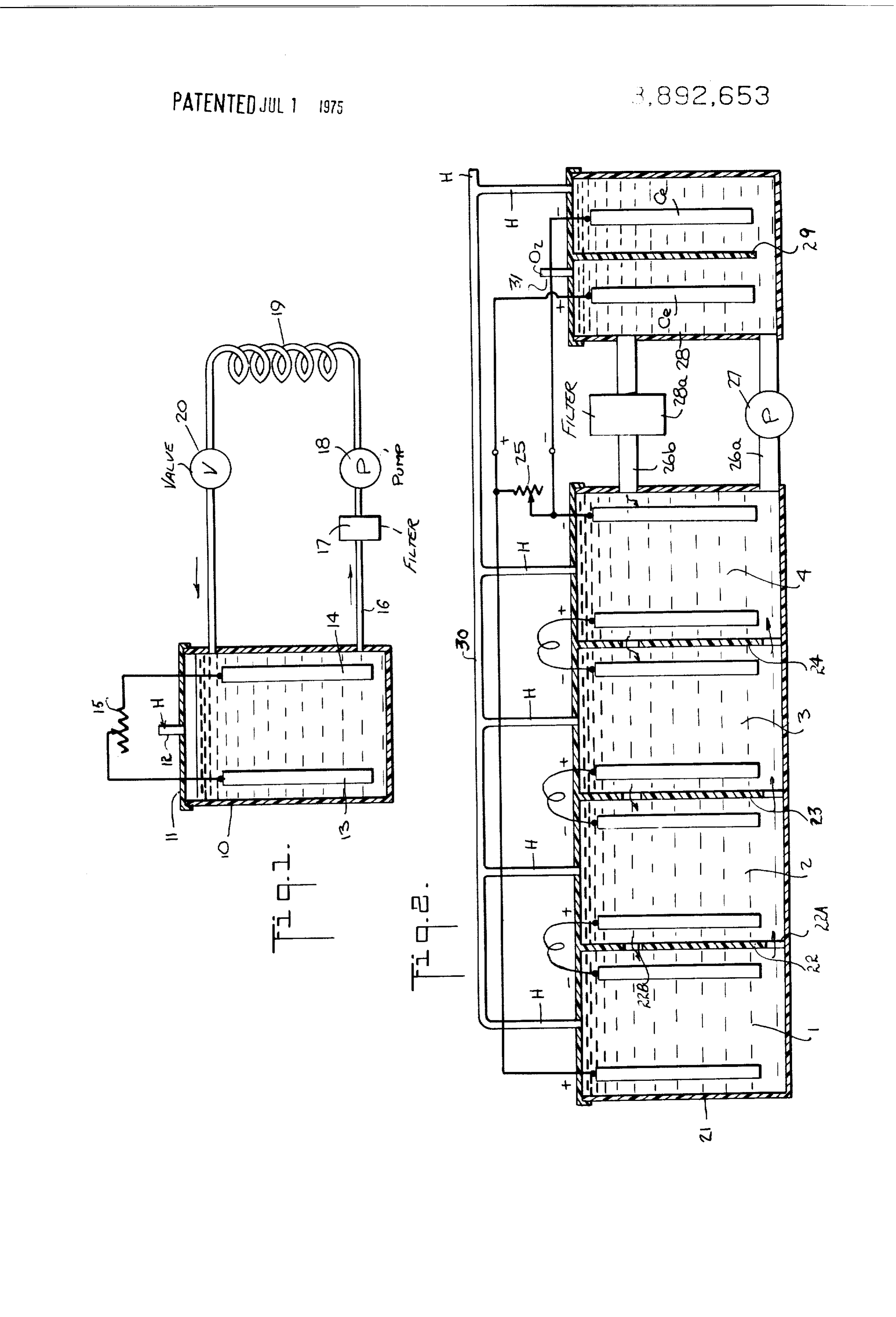
whereby the electrolyte is continuously circulated. The lyte becomes base in character, its temperature rises loop may include a heat exchange coil to reduce the and polarization occurs, all of which act to reduce the temperature of the electrolyte. hydrogen output. These adverse effects are minimized In another embodiment of the invention, the loop in by means of an external flow loop 16 which communi cludes an electrolysis cell having a pair of like elec cates at its input end with the bottom of the electrolyte trodes therein to which a voltage derived from the mag bath in tank 10 and at its return end with the top of the nesium cell is applied, whereby the hydrogen liberated bath.
in the electrolysis cell is added to the hydrogen gener Interposed in loop 16 is a strainer or filter 17 to col ated in the voltaic cell and the liberated oxygen is fed lect the magnesium hydroxide sediment, a pump 18, a to a separate output. O heat exchange coil 19 and a control valve 20. Pump 18 OUTLINE OF THE DRAWING is powered by voltage derived from cell 10, and since this voltage in a single cell is less than 1.5 volts, a suit
For a better understanding of the invention as well as able D-C voltage multiplier may, in practice, be used to other objects and further features thereof, reference is step up this voltage to a higher operating voltage, such made to the following detailed description to be read 15 as 24 volts.
in conjunction with the accompanying drawing, When the pump is operative, the electrolyte is drawn wherein: from the bottom of the bath by the pump and carried FIG. 1 is a schematic diagram of one preferred em through the filter 17 to remove sediment therefrom, the bodiment of the invention, and electrolyte then passing through cooling coil 19 before FIG. 2 is a schematic diagram of another preferred 20 it is returned to the top of the bath. Thus the electrolyte embodiment of the invention. is continuously circulated, in the course of which it is DESCRIPTION OF THE INVENTION purified and cooled to maintain operation of the cell at optimum efficiency.
First Embodiment
Referring now to FIG. 1, there is shown a hydrogen In the arrangement shown in FIG. 2, a group of iden generating voltaic cell in accordance with the invention tical voltaic cells 1, 2, 3 and 4 is provided. This group in which a salt or sea water electrolyte is contained in is formed in a common tank 21 divided into four cells a tank 10, preferably fabricated of a non-corrosive by partitions metal provided with an insulating liner, or of a high 30 a magnesium22, 23 and 24. Each cell is equipped with electrode Mg and a carbon electrode C.
strength synthetic non-reactive plastic material. The The cells are serially connected to an adjustable load cover 11 of tank 10 includes a gas-discharge outlet 2. resistor 25, so that the voltage applied to the load is 4 Supported within tank 10 and immersed in the elec times the voltage of a single cell. Obviously, in practice trolyte is an active magnesium electrode 13 and an in active electrode 14, preferably composed of carbon, 35 the arrangement may be scaled to define a greater number of voltaic cells.
steel or other conductive material which is non
The four cells formed in the tank have a common reactive. The tank is hermetically sealed except for the salt-water electrolyte, and in order to permit this elec outlet provided for the escape of hydrogen gas. Elec trolyte to circulate trodes 13 and 14 are interconnected by a variable load tion is provided withfreely from cell to cell, each parti resistor 15. This load may also include other electrical 40 and an upper port 22B.a lower port, such as port 22A, devices such as lamps and motors. Coupled to the tank 21 is an external flow loop whose When the electrodes are interconnected by the load lower branch 26A has a pump 27 interposed therein resistor, a current flows in the cell with an intensity de and whose upper branch 26B has a filter 28a interposed termined by the resistance of the load - the higher the therein.
resistance, the smaller the current. The rate of hydro 45 This loop passes through an electrolysis cell 28 gen production is proportional to current flow, this rate having a pair of spaced carbon electrodes Ce immersed being greatest where the load is effectively a short cir therein, which electrodes are isolated from each other by a divider 29 serving to segregate hydrogen gas cuit. In practice, in order to limit the amount of hydro evolved gen generated to the demand therefor, a control circuit (cathode)atandthethenegatively-biased carbon electrode oxygen evolved at the positively may be provided which is responsive to the level of de 50 biased carbon electrode (anode).
mand and functions to vary the load resistor to meet The voltage for operating the electrolysis cell is taken but not exceed the demand.
The electrochemical reaction which accompanies the from across load resistor 25. This voltage is also used decomposition of the magnesium electrode results in place to operate pump 27. No electrochemical action takes the formation of magnesium hydroxide which is depos 55 in the electrolysis cell, for in this cell it is only ited in the bottom of the tank. When the magnesium water which is decomposed. Since this water is derived electrode is consumed, it must be replaced. The mag from the voltaic cells where hydrogen peroxide is pro nesium hydroxide may be processed to recover its mag duced, this hydrogen peroxide is subjected to electroly nesium content. Concurrent with the electrochemical SS.
activity is electrolysis which liberates hydrogen. No sig 60 taicIn cells order to accumulate hydrogen from both the vol and the electrolysis cell, a manifold 30 is pro nificant amount of liberated oxygen passes out of the cell, for the oxygen becomes involved in the electro vided which is coupled to all of these cells. A separate chemical reaction and also forms hydrogen peroxide. outlet 31 is provided for the oxygen output. Inasmuch as the cell itself generates the voltage for It has been found that in the course of operation, the electrolysis, the cell operates as an auto-electrolysis de 65 electrolyte in voltaic cells 1, 2, 3 and 4 which is initially neutral in character becomes base, whereas the elec vice requiring no external voltage source. trolyte in the electrolysis cell 28 becomes acid. But be As previously noted, the electrolyte is initially neu tral. However, in the course of operation, the electro cause of the continuous circulation of the electrolyte
Page 5
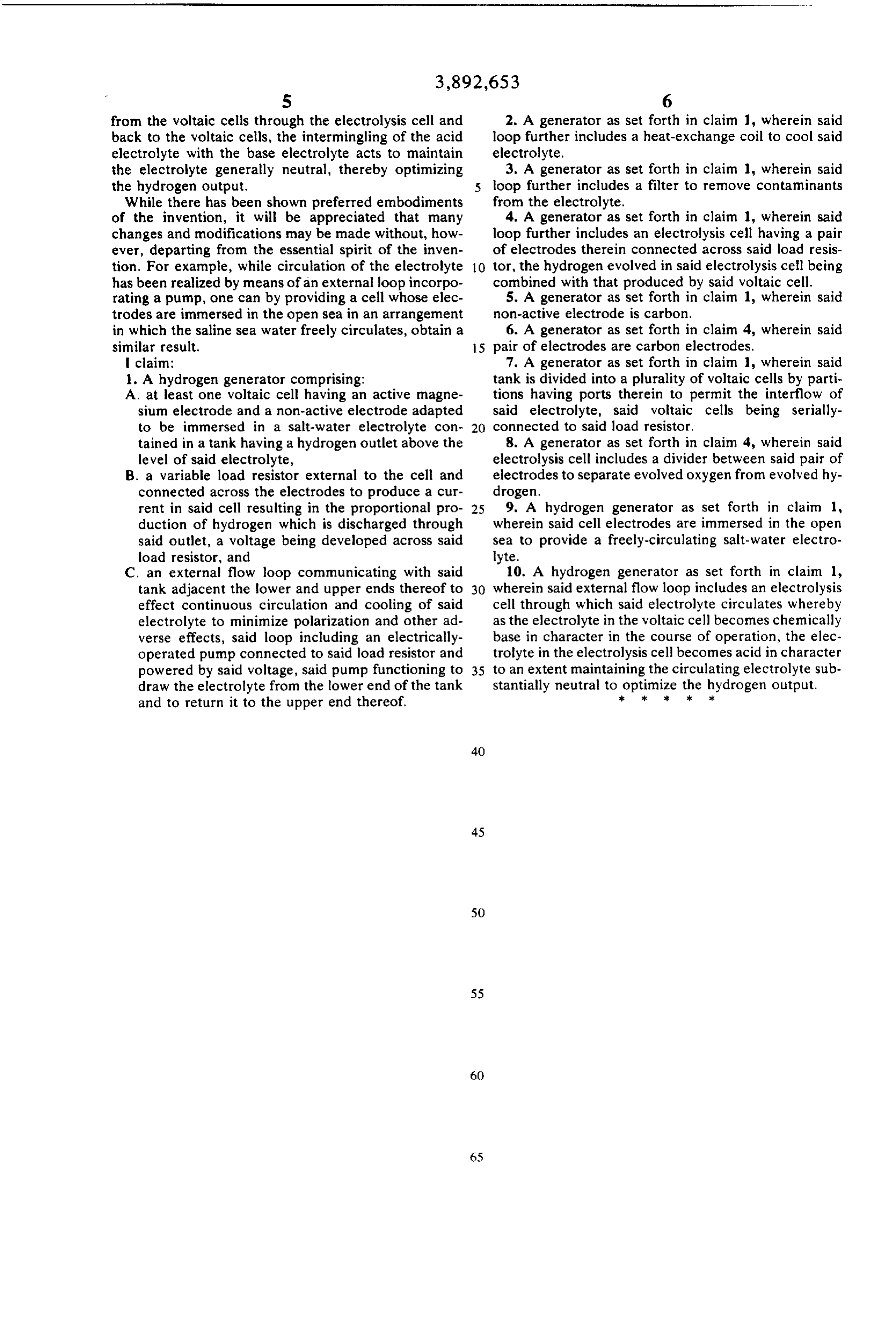
S 6 from the voltaic cells through the electrolysis cell and 2. A generator as set forth in claim 1, wherein said back to the voltaic cells, the intermingling of the acid loop further includes a heat-exchange coil to cool said electrolyte with the base electrolyte acts to maintain electrolyte.
the electrolyte generally neutral, thereby optimizing 3. A generator as set forth in claim 1, wherein said the hydrogen output. loop further includes a filter to remove contaminants While there has been shown preferred embodiments from the electrolyte.
of the invention, it will be appreciated that many 4. A generator as set forth in claim 1, wherein said changes and modifications may be made without, how loop further includes an electrolysis cell having a pair ever, departing from the essential spirit of the inven of electrodes therein connected across said load resis tion. For example, while circulation of the electrolyte O tor, the hydrogen evolved in said electrolysis cell being has been realized by means of an external loop incorpo combined with that produced by said voltaic cell. rating a pump, one can by providing a cell whose elec 5. A generator as set forth in claim 1, wherein said trodes are immersed in the open sea in an arrangement non-active electrode is carbon. in which the saline sea water freely circulates, obtain a 6. A generator as set forth in claim 4, wherein said similar result. 15 pair of electrodes are carbon electrodes, | claim: 7. A generator as set forth in claim 1, wherein said 1. A hydrogen generator comprising: tank is divided into a plurality of voltaic cells by parti A. at least one voltaic cell having an active magne tions having ports therein to permit the interflow of sium electrode and a non-active electrode adapted said electrolyte, said voltaic cells being serially to be immersed in a salt-water electrolyte con connected to said load resistor. tained in a tank having a hydrogen outlet above the 8. A generator as set forth in claim 4, wherein said level of said electrolyte, electrolysis cell includes a divider between said pair of B. a variable load resistor external to the cell and electrodes to separate evolved oxygen from evolved hy connected across the electrodes to produce a cur drogen.
rent in said cell resulting in the proportional pro 25 9. A hydrogen generator as set forth in claim 1, duction of hydrogen which is discharged through wherein said cell electrodes are immersed in the open said outlet, a voltage being developed across said sea to provide a freely-circulating salt-water electro load resistor, and lvte.
C. an external flow loop communicating with said io. A hydrogen generator as set forth in claim 1, tank adjacent the lower and upper ends thereof to 30 wherein said external flow loop includes an electrolysis effect continuous circulation and cooling of said cell through which said electrolyte circulates whereby electrolyte to minimize polarization and other ad as the electrolyte in the voltaic cell becomes chemically verse effects, said loop including an electrically base in character in the course of operation, the elec operated pump connected to said load resistor and trolyte in the electrolysis cell becomes acid in character powered by said voltage, said pump functioning to 35 to an extent maintaining the circulating electrolyte sub draw the electrolyte from the lower end of the tank stantially neutral to skoptimize
the hydrogen output.
and to return it to the upper end thereof.
Provenance
- Collection
- Cited prior art
- Original PDF
- patentimages.storage.googleapis.com →
- Filed
- 1973-11-14
- Pages
- 5
- Method
- pdftotext (the PDF's own text layer) + pdftoppm 300dpi page scans
- Source
- Google Patents bibliographic record
- Granted
- 1975-07-01
- Inventors
- Francisco Pacheco
- Transcribed from
- patentimages.storage.googleapis.com →