patent · US4037655
Method for secondary recovery of oil
26 July 1977
Page 1 — bibliographic record
United States Patent (19) 11 4,037,655 Carpenter 45 July 26, 1977
(54) METHOD
FOR SECONDARY RECOVERY OTHER PUBLICATIONS 75 Inventor: Neil L. Carpenter, Kerrville, Tex. Composite Catalog of Oil Field Equipment & Services,
73) Assignee: Electroflood Company, Houston, Houston, Texas. w Tex. Muskat, “Physical Principles of Oil Production”, 1st 21 Appl. No.: 624,391 Edition, 1949, McGraw-Hill Book Co., Inc. N.Y., N.Y. Primary Examiner-Stephen J. Novosad (22 Filed: Oct. 21, 1975 Attorney, Agent, or Firm-Bard, Springs, Jackson & Groves
Related U.S. Application Data
abandoned, which is a continuation-in-part of Ser. No. In one exemplar embodiment, method and apparatus 228,846, Feb. 24, 1972, abandoned. include providing an electrode disposed in a plurality of 51) Int. Cl’.............................................. E21B 43/24 vertically spaced boreholes penetrating the formation.
52 U.S. C. .................................... 166/248; 166/245; The plurality of electrodes in contact with the salt water and oil of the formation are connected to a source 166/60; 166/272; 166/303 of electrical power for establishing an AC electrical 58) Field of Search ............... 166/248, 60,272, 65 R, field of current flow between the spaced elctrodes. The 166/303, 245; 204/129 electrodes are insulated from the earth structure sur 56) References Cited rounding the borehole for preventing an electrical cur
for isolating the electrical current path from the elec 849,524 4/1907 Baker ................................... 166/248 trode into the formation. The AC electrical current 1,784,214 12/1930 Workman ............................ 166/248 path through the formation generates volumes of free 2,799,641 7/1957 Bell ... ... 166/248 hydrogen in the formation where it is trapped for in 3,507,330 4/1970 Gill ....................................... 166/248 creasing the formation pressure. The increased pressure 3,518,036 6/1970 Staats et al. ... ... 204/129 X 3,547,193 12/1970 Gill ....................................... 166/248 of the formation will drive the oil into producing bore 3,605,888 9/1971 Crowson et al. .................... 166/248 holes spaced from the electrode boreholes. 3,620,300 1 1/1971 Crowson .............................. 166/248 3,782,465 l/1974 Bell et al. ............................. 166/248 10 Claims, 18 Drawing Figures
Page 2
Drawing sheet — no readable text.
Page 3
Drawing sheet — no readable text.
Page 4
Drawing sheet — no readable text.
Page 5
Drawing sheet — no readable text.
Page 6
Drawing sheet — no readable text.
Page 7
Drawing sheet — no readable text.
Page 8
hance the flow characteristics of the oil or an "electro
METHOD FOR SECONDARY RECOVERY OF OIL osmosis' action whereby the oil tends to flow from an electrically charged positive region to a negatively
CROSS-REFERENCE TO RELATED charged region. However, none of the above patents APPLICATION suggests the establishment of a zone of electrochemical This is a continuation of co-pending U.S. Pat, applica activity wherein an electrochemical reaction is pro tion Ser. No. 462,326, filed Apr. 19, 1974, now aban moted with constituent elements of the formation, salt doned, which was a continuation-in-part of co-pending water and oil, for increasing the internal pressure of the U.S. Pat. Application Ser. No. 228,846, filed Feb. 24, formation over an area greatly exceeding the zone of 1972, now abandoned, electrochemical activity. 10 elect
Accordingly, one primary feature of the present in
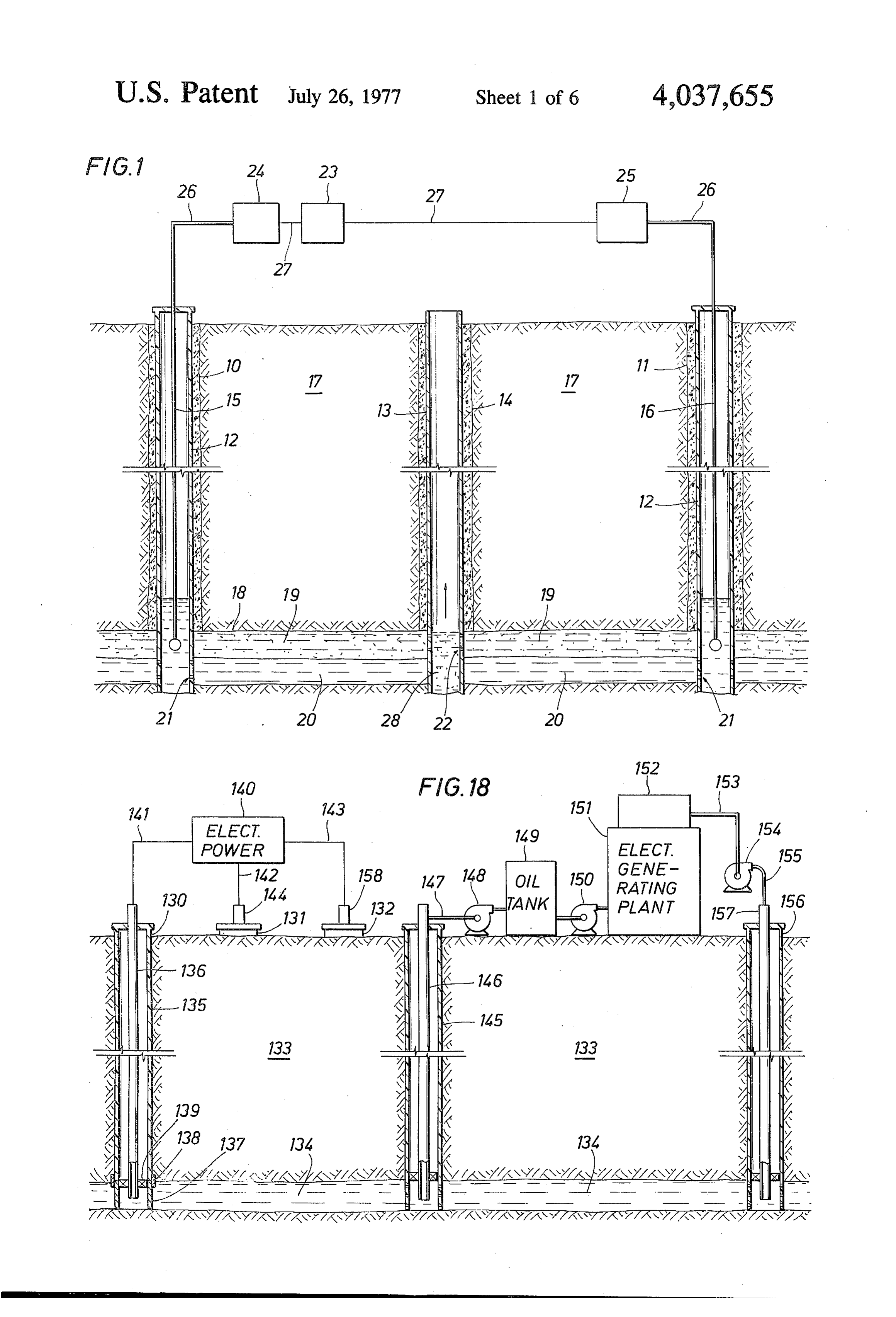
BACKGROUND OF THE INVENTION vention is to provide method and apparatus for estab This invention relates to method and apparatus for lishing a zone of electrochemical activity in a subsur face formation resulting in electrochemical reactions establishing an A.C. electrical field in a subsurface oil or mineral bearing formation and establishing in response 15 with constituent elements of the formation, such as salt to the electrical field a zone of electrochemical activity water and oil, for generating volumes of gas in the resulting in electrochemical reactions with constituent formation for increasing the formation pressure. elements of the earth formation for increasing the inter Another feature of the present invention is to provide nal pressure of the earth formation over an area greatly method and apparatus for establishing a zone of electro exceeding the zone of electrochemical activity. 20 chemical activity in a subsurface formation for enhanc Until fairly recent times, it was relatively easy to find ing the flow characteristics of oil in the formation by new oil reserves when a field was depleted or became lowering the viscosity of the oil.
unprofitable. In many fields only 15-25% of the oil in Yet another feature of the present invention is to place was actually recovered before reservoir pressure provide method and apparatus for establishing a zone of or drive was depleted or other factors made it uneco 25 electrochemical activity in a subsurface formation for nomical to continue to produce the field. As long as releasing salt water and oil in situ from the formation new reserves were readily available, old fields were matrix within the zone of electrochemical activity and abandoned. However, with the crisis now confronting separating the oil and saltwater within the earth forma the domestic oil industry, coupled with the fact that tion matrix by gravitational action.
most of the existing on-shore oil in the United States has 30 Still another feature of the present invention is to . already been discovered, it is obvious that such known provide method and apparatus for establishing an elec reserves must be efficiently and economically pro tric field within the subsurface formation wherein a duced. , plurality of electrodes is employed, each of the elec It has been estimated that at least 50% of the known trodes projecting into the formation through one of a oil reserves of the United States cannot be recovered 35 plurality of spaced boreholes and an insulating means is using conventional pumping methods. A substantial utilized for insulating each of the electrodes from the amount of this oil is of an abnormally low gravity, and earth structure surrounding the borehole for preventing /or high viscosity, often coupled with the fact that an electrical current path between the electrode and the there is little or no pressure in the oil-bearing formation. earth structure and isolating the electrical current path In the absence of formation pressure, even oil of aver 40 from the electrode into the earth formation. age viscosity and gravity is difficult to produce without SUMMARY OF THE INVENTION adding external energy to the formation to move the oil into a producing borehole. Accordingly, a great deal of The present invention remedies the problems of the attention has recently been given to various methods of prior art by providing a method of secondary oil recov secondary recovery. Water flooding has been utilized 45 ery from a subsurface earth formation comprising estab with mixed results to attempt to increase the natural lishing an A.C. electrical field within the subsurface reservoir pressure hydraulically. Thermal flooding formation generally defined by a plurality of spaced techniques, such as fire flooding, steam injection and electrodes extending into the formation and establishing hot water flooding have been utilized to alter the viscos a zone of electrochemical activity in the formation in ity of the oil and hence, enhance its flow characteristics. 50 response to the established electrical field and generally However, none of these thermal techniques contributes defined by the electrical field and resulting in electro to increasing the formation pressure and have been chemical reactions with constituent elements of the successful only in a limited number of applications. All earth formation, such as salt water and oil, for increas of the methods mentioned above require extensive, and ing the internal pressure of the earth formation over an quite expensive, surface installations for their utiliza 55 area exceeding the zone of electrochemical activity by tion, generating volumes of free hydrogen in the formation. The prior art contains patents that have introduced The zone of electrochemical activity also enhances the electrical currents into a subsurface oil- or mineral-bear flow characteristics of the oil by lowering the viscosity ing formation for the express purpose of heating the of the oil. The increased pressures of the formation act formation in order to lower the viscosity and stimulate to drive oil into a producing borehole spaced from the the flow of the oil or mineral in the immediate area zone of electrochemical activity. The electrochemical involved in the heating process. Examples of such pa activity also releases the salt water and oil from the tents are: U.S. Pat. No. 849,524 (Baker, 1907); 2,799,641 earth formation matrix within the zone of electrochemi (Bell, 1957); 2,801,090 (Hoyer, 1957); 3,428,125 (Parker, cal activity and separates the oil and salt water within 1969); 3,507,330 (Gill, 1970); 3,547,193 (Gill, 1970); 65 the earth formation matrix by gravitational action. 3,605,888 (Crowson, 1971); 3,620,300 (Crowson, 1971), The apparatus for accomplishing the above described and 3,642,066 (Gill, 1972). All of the above patents method is, in one preferred embodiment, comprised of a depend in some form on electrothermic action to en plurality of spaced boreholes drilled into the earth for
Page 9
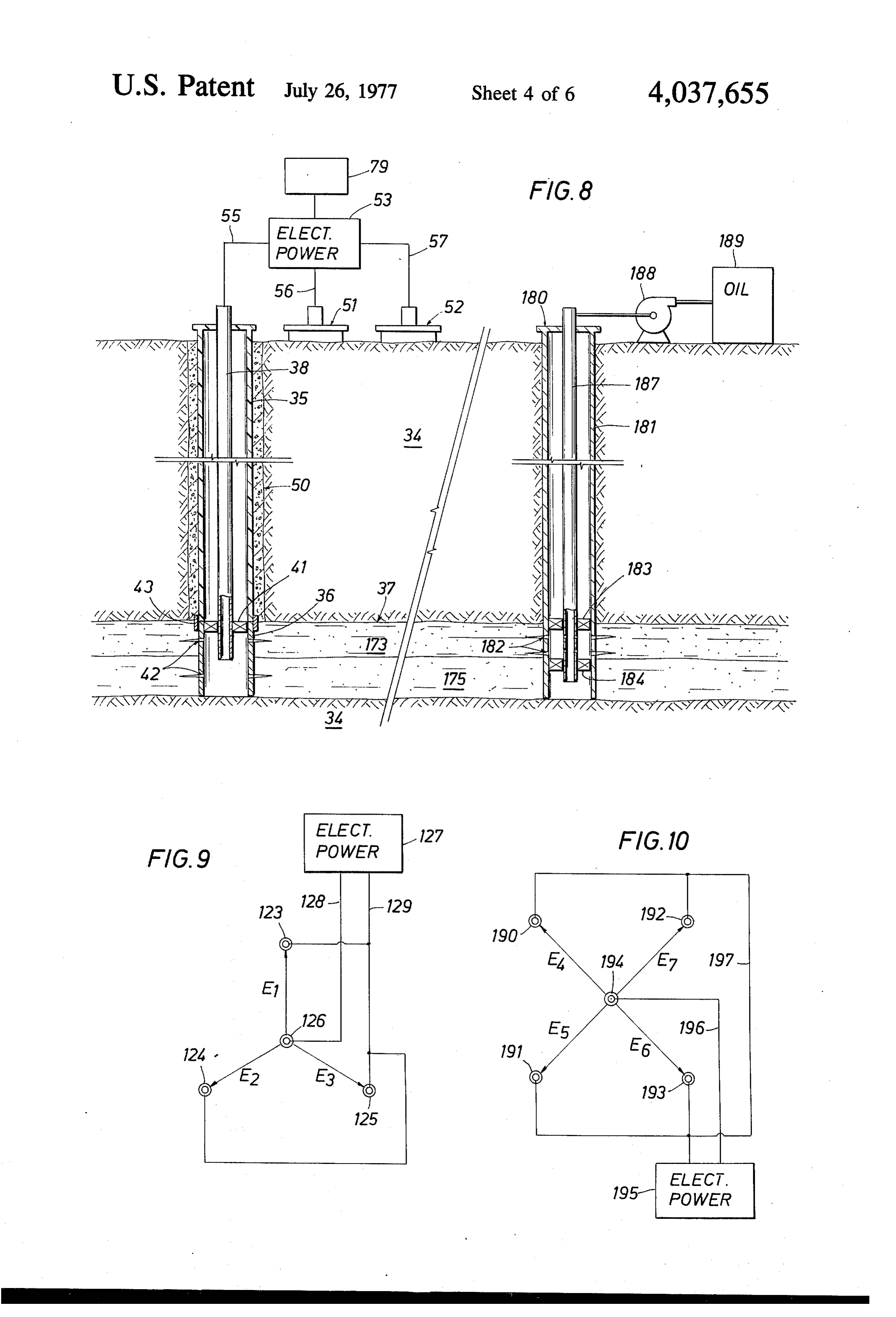
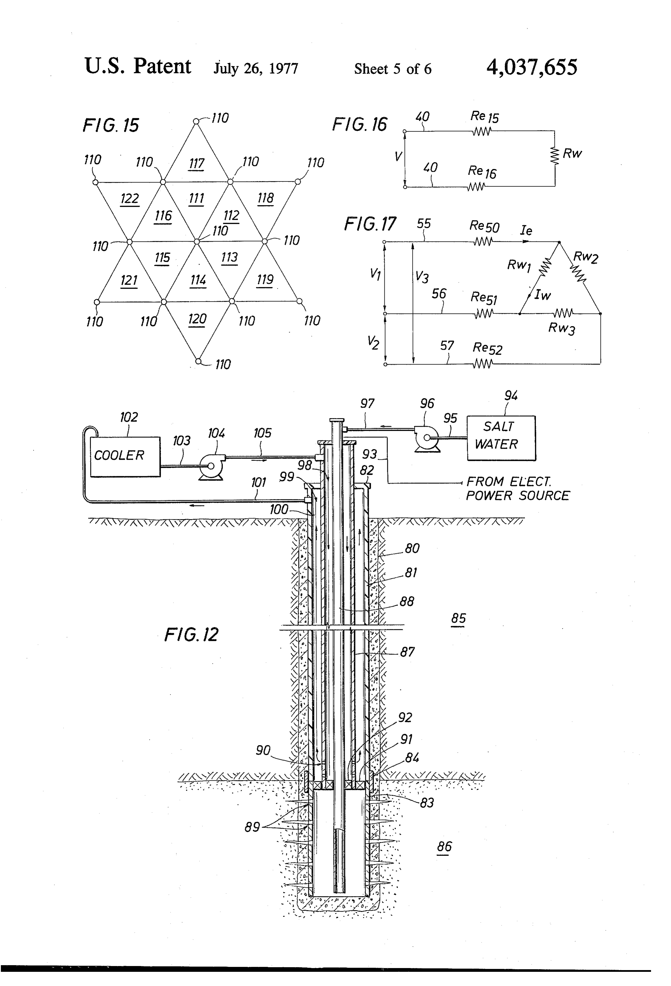
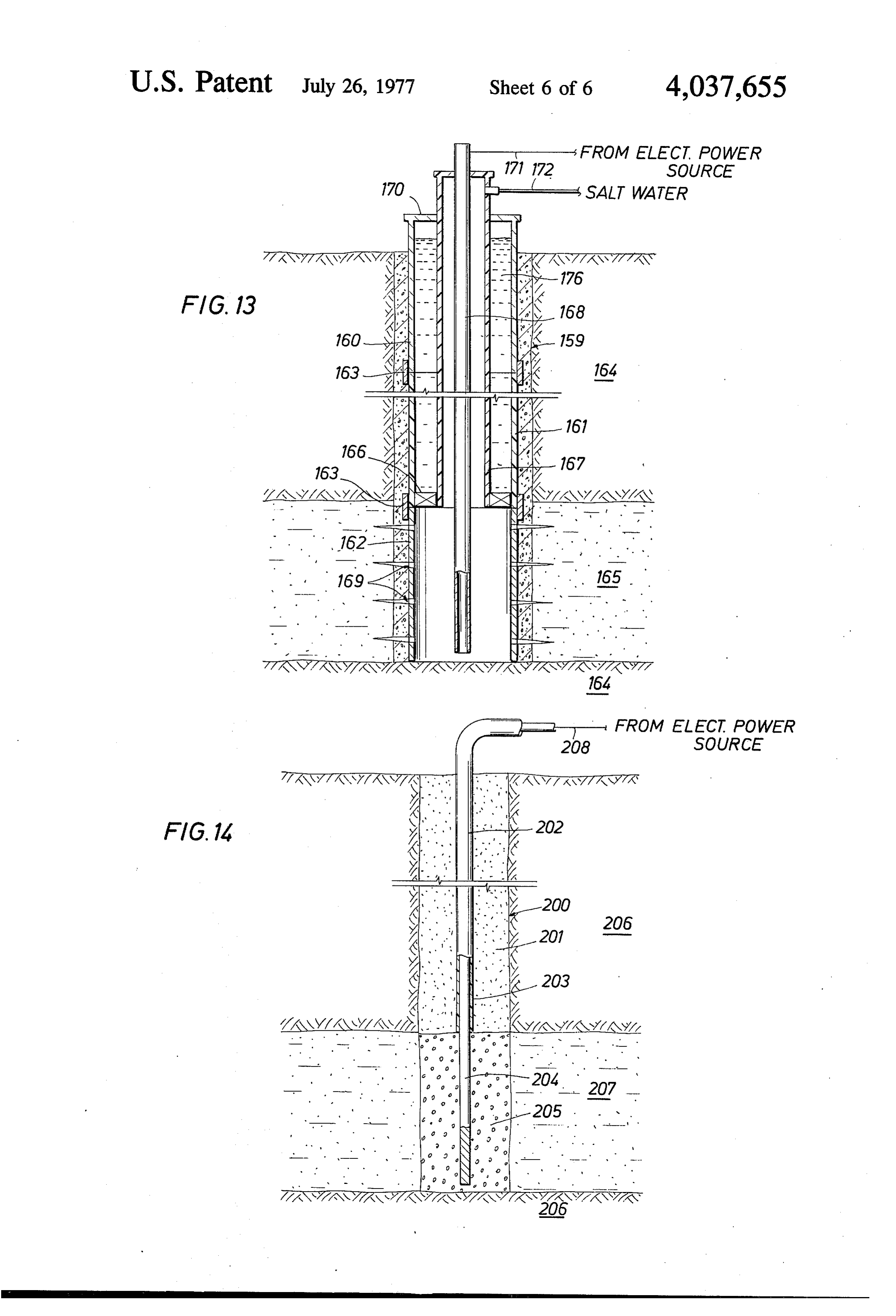
mation, a plurality of electrodes, one each of which is FIG. 10 is a diagrammatic view showing a fourth disposed in each of the boreholes extending from the suggested distribution of electrode wells in accordance surface of the earth into the subsurface earth formation, with a fourth embodiment of the invention. a source of electrical current connected to each of the FIG. 11 is a cross-sectional view, illustrating one en electrodes for establishing an electrical field within the 5 bodiment of the apparatus for equipping an electrode subsurface earth formation generally defined by the well bore penetrating an oil-bearing formation; plurality of spaced electrodes, and a producing bore FIG. 12 is a cross-sectional view illustrating another hole drilled into the earth formation spaced from the embodiment of the apparatus for equipping an electrode electrode boreholes for removing oil from the earth well bore penetrating an oil-bearing formation; formation. In another preferred embodiment, the insu 10 FIG. 13 is a cross-sectional view illustrating yet an lating means may be electrically insulating casing set other embodiment of the apparatus for equipping an into each of the boreholes between the surface of the electrode well bore penetrating an oil-bearing forma earth and the top of the subsurface earth formation. tion; . . .. Other means may be added to an electrode well for FIG. 14 is a cross-sectional view illustrating still an cooling the casing of the well from the heat generated 15 other embodiment of the apparatus for equipping an by the passage of electrical current in the formation. electrode well bore penetrating an oil-bearing forma
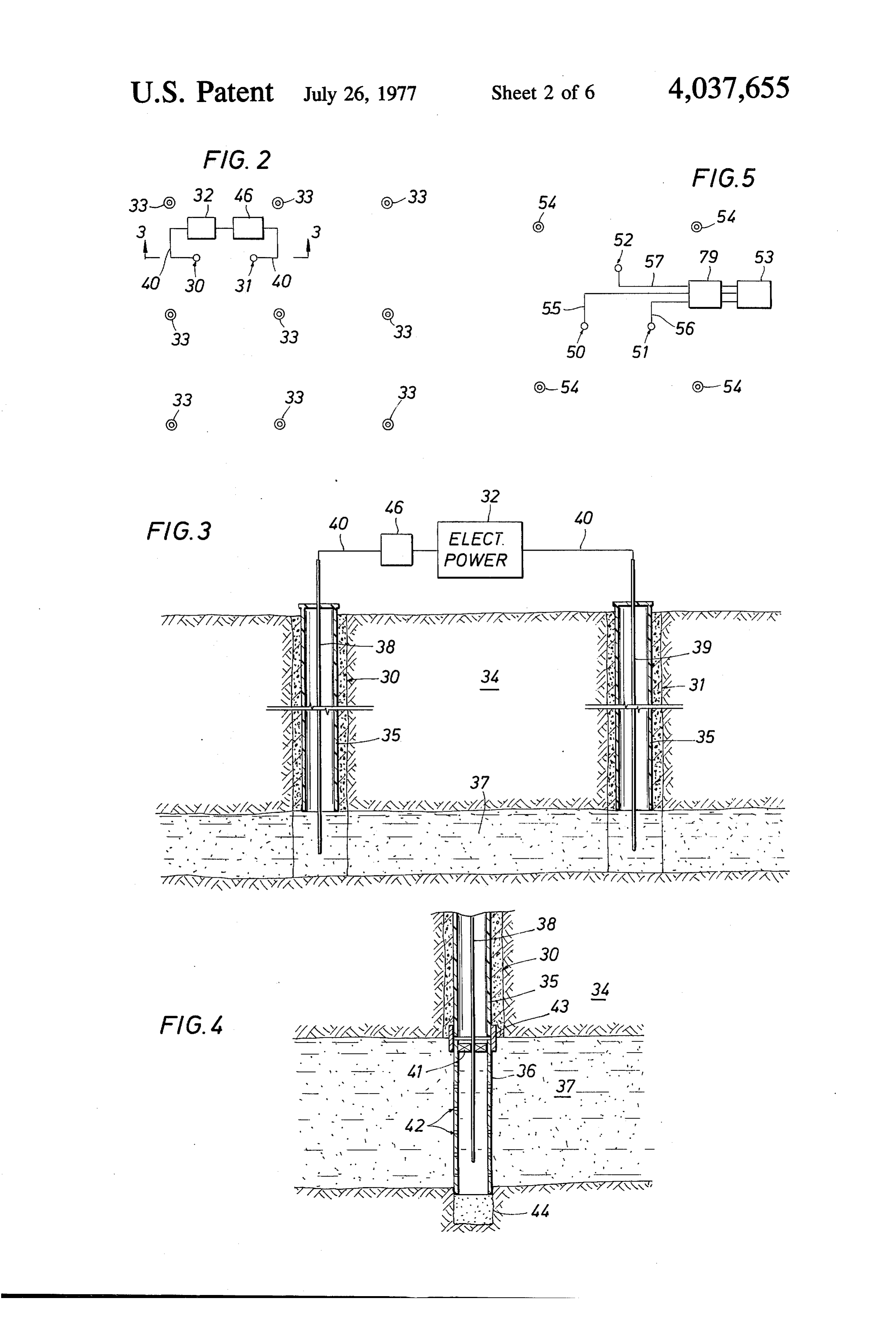
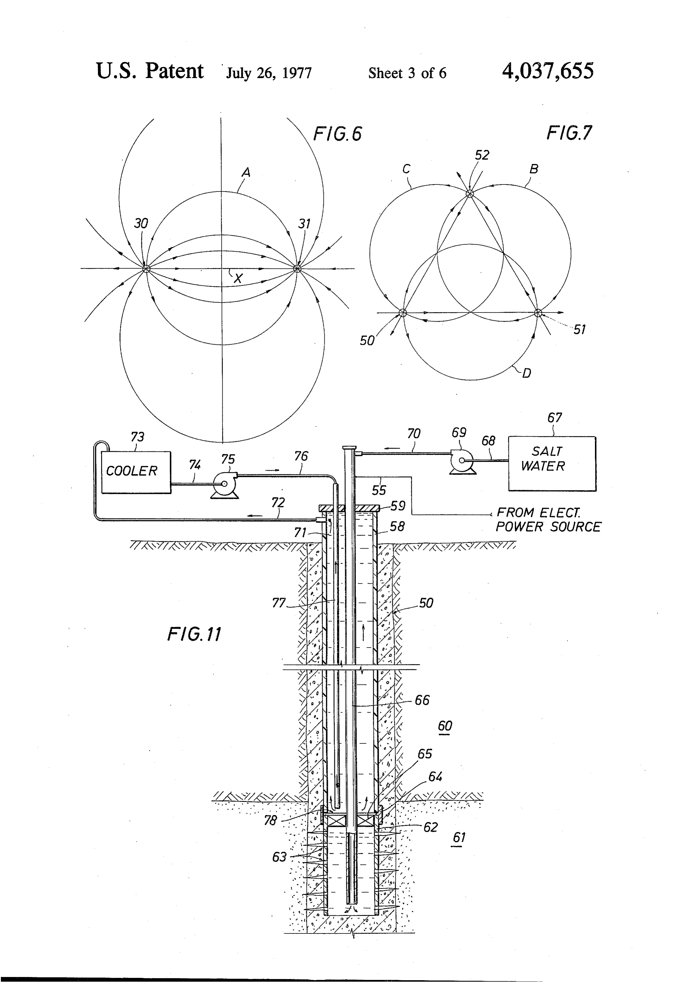
BRIEF DESCRIPTION OF THE DRAWINGS FIG. 15 schematically illustrates one manner in which In order that the manner in which the above-recited 20 the principles of the present invention can be applied to advantages and features of the invention are attained produce a series of current-producing patterns for pass can be understood in detail, a more particular descrip ing electric current through an increasing area of an tion of the invention may be had by reference to specific earth formation; . embodiments thereof which are illustrated in the ap FIG. 16 schematically illustrates the path for flow of pended drawings, which drawings form a part of this current in accordance with the embodiment of the in specification. It is to be noted, however, that the ap- 25 vention illustrated in FIG. 2;
pended drawings illustrate only typical embodiments of FIG. 17 schematically illustrates the path for flow of the invention and therefore are not to be considered current in accordance with the embodiment of the in limiting of its scope, for the invention may admit to vention illustrated in FIG. 5;
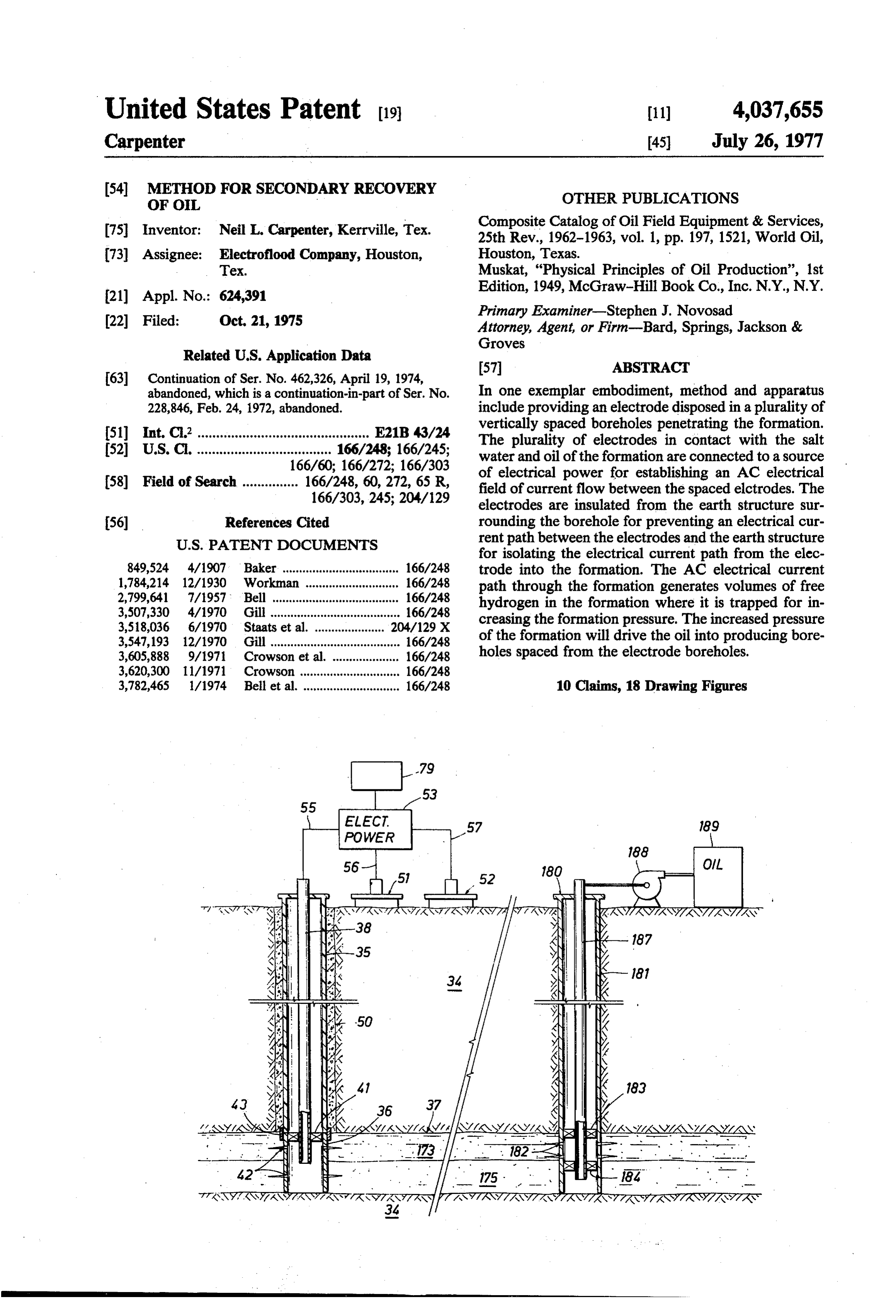
further equally effective embodiments. FIG. 18 is a diagrammatic view, partly in cross-sec In the drawings: 30 tion, illustrating a plurality of electrode well bores pen FIG. 1 is a cross-sectional view illustrating a pair of etrating an oil-bearing formation, a producing well bore electrode well bores penetrating an oil-bearing forma penetrating the oil-bearing formation, and an industrial tion for passing electric current therethrough in accor plant utilizing an oil-fueled energy source with the ex dance with one embodiment of the present invention; haust gases from the plant being injected into the oil FIG. 2 is a diagrammatic view showing one suggested 35 bearing formation through yet another well penetrating distribution of electrode wells in accordance with a said formation. . .. . . second embodiment of this invention, with the elec trode wells shown in relation to conventional oil-pro DETAILED DESCRIPTION OF THE
PREFERRED EMBODIMENTS
ducing wells;
FIG. 3 is a cross-sectional view illustrating a pair of 40 For a formation or reservoir to be productive, a cou electrode well bores penetrating an oil-bearing forma ple of conditions must exist. First, a pressure differential tion adapted for passing an electric current there must exist between the formation and the well bore. through in accordance with the second embodiment of Energy for the pressure differential may be supplied the present invention; naturally in the form of gas, either free or in solution, FIG. 4 is a fragmentary detailed view of another 45 evolved under a reduction in pressure. The energy may embodiment of the apparatus disposed in a borehole involve a hydrostatic head of water behind the oil, or shown in FIG.3 penetrating the oil-bearing formation; the water under compression. In cases where the natu FIG. 5 is a diagrammatic view showing a second ral energy forces within the formation are not sufficient suggested distribution of electrode wells in accordance to overcome the retarding forces within the formation with a third embodiment of this invention with the 50 or reservoir, external energy must be added. Secondly, electrode wells shown in relation to conventional oil the produced oil must be displaced by another fluid, producing wells; either gas or water. . .. . FIG. 6 is a diagrammatic view illustrating lines of Reservoirs are ordinarily classified according to the current in a subsurface formation between a pair of type of reservoir energy that is available. The four types electrode wells. 55 are solution gas drive reservoirs, gas expansion reser FIG. 7 is a diagrammatic view illustrating lines of voirs, water driving reservoirs, and gravitational drain current in a subsurface formation between three elec age reservoirs. A particular reservoir may, of course, trodes utilizing three-phase AC current. involve more than one of these producing mechanisms. FIG. 8 is a diagrammatic view, partly in cross-sec In those cases where the natural energy of the reser tion, illustrating a plurality of electrode well bores pen voir is insufficient to overcome the resistive forces such etrating an oil-bearing formation in accordance with the as the forces of viscous resistance and the forces of embodiment illustrated in FIG. 5 and illustrating the capillary action, external energy must be applied. To relationship between the electrode well bores and a illustrate such cases, this phenomenon is typically en producing well where the oil and salt water have been countered in shallow formations containing high viscos released from the formation matrix; 65 ity oil that has little or no reservoir energy or formation FIG. 9 is a diagrammatic view showing a third sug pressure available, and in those oil-producing forma gested distribution of electrode wells in accordance tions in which the reservoir energy has been depleted or . with a third embodiment of the invention. dissipated. In this discussion, we have been referring to
Page 10
"mechanical' forces acting within the producing for casing 12 and into the salt water zone 20 of the forma mation. In a formation in which the natural energy of tion 18, the reservoir has been depleted, the mechanical forces Oil is a poor conductor of electricity, while salt water in the formation have reached near equilibrium and no disposed in a formation is a good conductor. Since an pressure differential is available to drive the oil from the 5 electric current will follow the path of least resistance, formation into the well bore. In all of the cases where current which is applied to the electrodes 15 and 16 reservoir energy was depleted by conventional primary from the power supply 23 will flow directly across the production, or non-existent in the first instance, the salt water zone 20 of the formation 18 between the two chemical balance of the producing formation remains electrodes 15 and 16, and the salt water therein will tend undisturbed and in virtual equilibrium. 10 to be heated in accordance with the amount of salt Artificial forces introduced into the reservoir such as water which is interposed therebetween and the magni water or gas through various "pressuring' or "flood' tude of current being applied to the electrodes 15 and techniques of secondary recovery can effect a mechani 16. The heated salt water will act as a heating element cal change in the formation by way of pressure. Steam with respect to the oil in the zone or strata 19, whereby pressure is likewise effective, with some side benefits 15 the viscosity of the oil may be decreased, thus enhanc from heat. Combustion of some of the oil in the forma ing the flow characteristics of the oil in the formation. tion through "fire-flooding' and heating a well bore The above discussion relating to FIG. 1 assumes a serve to reduce the viscosity of the oil in place and heating of a defined salt water strata in an oil-bearing enhance flow characteristics but lack a drive to force formation which will heat the overlying oil strata, the oil through the formation and into a producing well 20 thereby lowering the viscosity of the oil and improving bore. However, these are primarily mechanical forces its flow characteristics in the formation. However, if a applied and operating only on an exposed face or sur natural driving energy is not present in the reservoir or face of the formation, and if some chemical or molecu formation, lowering the viscosity of the oil will not lar change is accomplished in the fluids in the forma 25 greatly enhance oil production, since there is no forma tion, it is limited to a localized phenomenon. The instant tion pressure or force available to move the oil from the invention will enhance the flow characteristics of the oil formation to the bore hole. For reasons to be hereinafter in the formation and generate energy in the form of gas further described, transmitting an electric current produced in the formation for increasing the formation through the formation fluids, such as salt water or strata differential pressure and thus the available reservoir 30 20 of formation 18, will generate volumes of gas within energy. These factors are achieved by applying electric the formation 18 by electro-chemical action for provid current to the formation resulting in an electro-chemi ing internal formation pressure to drive the oil into cal action on the fluids in the formation. producing borehole 14 of FIG. 1. Referring now to FIG. 1, there may be seen a simpli Referring now to FIGS. 2, 3 and 4, another embodi fied diagrammatic illustration of a portion of a subsur 35 ment of the apparatus for secondary recovery of oil face earth formation 18 containing both oil and salt from a subsurface oil-bearing earth formation is dis water. More particularly, the formation 18 may be seen closed. A pair of boreholes 30 and 31 are shown pene to have been penetrated by three separate boreholes 10, trating the overlying earth 34 and an oil-producing 11 and 14. Two of these boreholes, 10 and 11, are prefer earth formation 37. Boreholes 30 and 31 are preferably ably lined with an electrically non-conductive or insu lined with an electrically non-conductive casing 35 and lating casing 12, whereas the third or producing bore conventionally cemented down to the point at which hole 14 may be lined with conventional steel casing 13. the earth 34 adjoins the oil-bearing formation 37. In the Because of the action of the force of gravity, it will be embodiment of FIG. 3, the boreholes are completed noted that the oil in the formation 18 will usually tend to "barefoot,' that is, no casing is set in the oil-bearing collect in the upper reaches or strata 19 of the formation 45 formation 37 and the borehole is left unlined. In FIG. 4, 18, whereas, the salt water, which is heavier than oil, another embodiment is shown, where a steel casing will tend to collect in the lower portion or strata 20 of section 36 is set in the borehole in formation 37 and has the formation 18 beneath the oil. Accordingly, the elec perforations 42 completed therein. Collar 43 couples the trically non-conductive casing 12 in the two boreholes insulating casing 35 and steel casing 36. The steel casing 10 and 11 will preferably be provided with perforations 50 36 can be anchored by a conventional cement plug 44. 21 at a level in the lower salt water zone or strata 20 of A pair of metal electrodes 38 and 39 are inserted one the formation 18, whereas the steel casing 13 in the third into each of boreholes 30 and 31, respectively, and ex well 14 will preferably have perforations 22 at an upper tend through the insulating casing 35 into the oil-bear level in the oil zone or strata 19 of the formation 18. ing formation 37 as shown in FIG. 3 or into the steel or Thus, only the salt water 28 in the formation 18 will 55 electrically conducting casing section 36, as shown in tend to enter and at least partially fill the casing 12 of FIG. 4. The electrodes may be centralized within insu the two boreholes 10 and 11. lating casing 35 by means of packers (not shown in FIG. Referring again to FIG. 1, it may be seen that a pair of 3) and within the electrically conducting casing section metallic electrodes 15 and 16 have been inserted to a 36 (see FIG. 4) by means of a packer 41 that is set just depth in each of the two wells 10 and 11, whereby their 60 below the joint of the insulating casing 35 and the elec lower ends are each deeply immersed in the salt water trically conducting casing 36 for purposes to be herein which is collected in the casing 12. The upper ends of after further explained. Electrical power is provided by both electrodes 15 and 16 are connected by suitable generator 32 and is connected to electrodes 38 and 39 leads 26 and suitable regulating and control equipment by means of conductors 40. Suitable regulating and 24 and 25 to an electrical power supply 23 by means of 65 timing apparatus 46 may be utilized to regulate the conductors 27. The electrical power supply 23 is of electric power and to time the length of the application appropriate size and capacity for generating electric of power to the formation, as will hereinafter be further current that may be conducted into the contents of explained.
Page 11
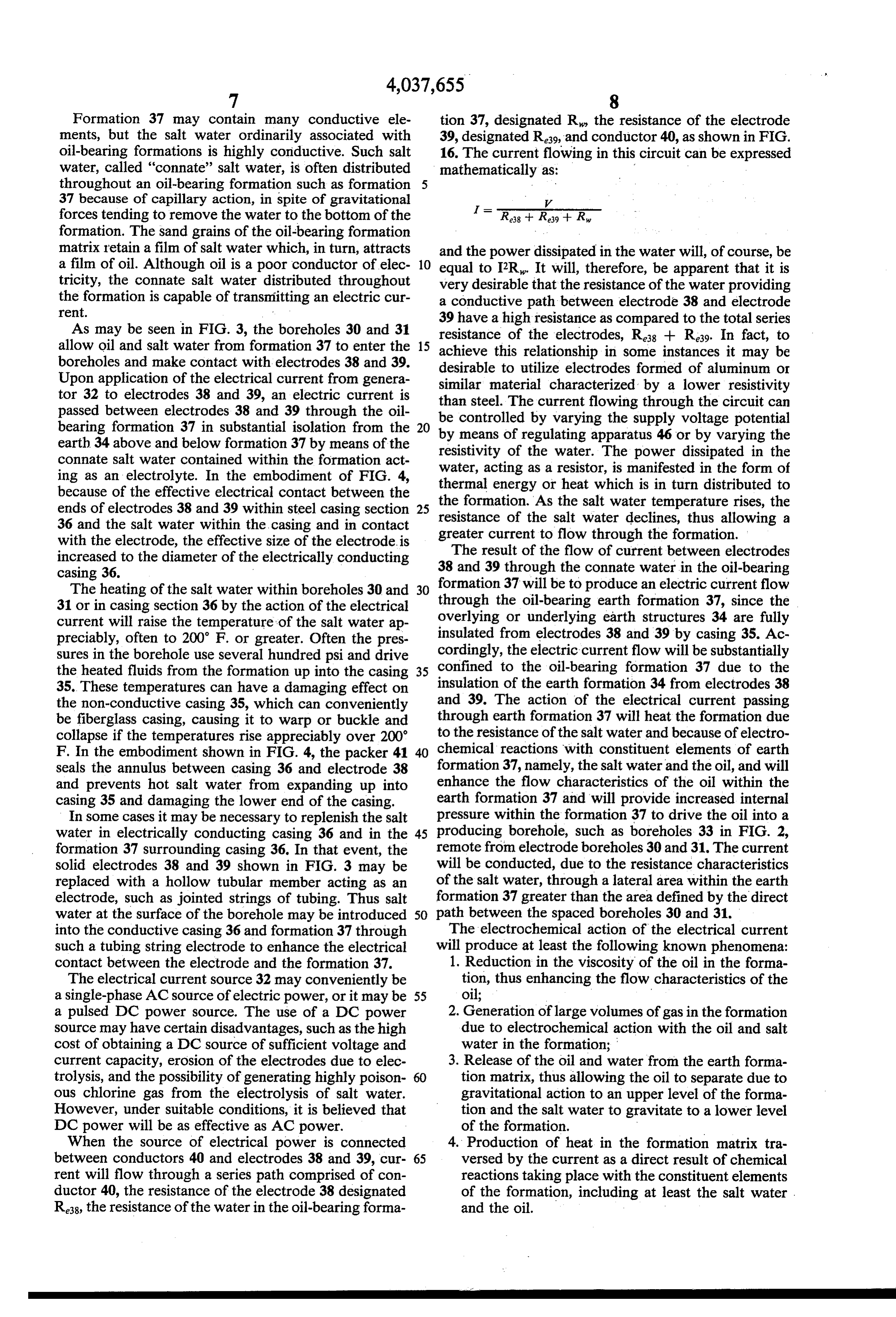
Formation 37 may contain many conductive ele tion 37, designated R, the resistance of the electrode ments, but the salt water ordinarily associated with 39, designated R39, and conductor 40, as shown in FIG. oil-bearing formations is highly conductive. Such salt 16. The current flowing in this circuit can be expressed water, called "connate' salt water, is often distributed mathematically as:
throughout an oil-bearing formation such as formation 37 because of capillary action, in spite of gravitational =
forces tending to remove the water to the bottom of the R38 -- Rs.9 - R. formation. The sand grains of the oil-bearing formation matrix retain a film of salt water which, in turn, attracts and the power dissipated in the water will, of course, be a film of oil. Although oil is a poor conductor of elec 10 equal to I2R. It will, therefore, be apparent that it is tricity, the connate salt water distributed throughout very desirable that the resistance of the water providing the formation is capable of transmitting an electric cur a conductive path between electrode 38 and electrode rent.
39 have a high resistance as compared to the total series
As may be seen in FIG. 3, the boreholes 30 and 31 resistance of the electrodes, Ra8 + R39. In fact, to allow oil and salt water from formation 37 to enter the 15 achieve this relationship in some instances it may be boreholes and make contact with electrodes 38 and 39. desirable to utilize electrodes formed of aluminum or Upon application of the electrical current from genera similar material characterized by a lower resistivity tor 32 to electrodes 38 and 39, an electric current is than steel. The current flowing through the circuit can passed between electrodes 38 and 39 through the oil be controlled by varying the supply voltage potential bearing formation 37 in substantial isolation from the 20 by means of regulating apparatus 46 or by varying the earth 34 above and below formation 37 by means of the resistivity of the water. The power dissipated in the connate salt water contained within the formation act ing as an electrolyte. In the embodiment of FIG. 4, water, acting as a resistor, is manifested in the form of thermal energy or heat which is in turn distributed to because of the effective electrical contact between the ends of electrodes 38 and 39 within steel casing section 25 the formation. As the salt water temperature rises, the resistance of the salt water declines, thus allowing a 36 and the salt water within the casing and in contact greater current to flow through the formation. with the electrode, the effective size of the electrode is The result of the flow of current between electrodes increased to the diameter of the electrically conducting 38 and 39 through the connate water in the oil-bearing casing 36.
formation 37 will be to produce an electric current flow
The heating of the salt water within boreholes 30 and 30 through 31 or in casing section 36 by the action of the electrical overlyingtheor oil-bearing earth formation 37, since the underlying earth structures 34 are fully current will raise the temperature of the salt water ap preciably, often to 200 F. or greater. Often the pres insulated from electrodes 38 and 39 by casing 35. Ac cordingly, the electric current flow will be substantially sures in the borehole use several hundred psi and drive confined the heated fluids from the formation up into the casing 35 to the oil-bearing formation 37 due to the 35. These temperatures can have a damaging effect on insulation of the earth formation 34 from electrodes 38 the non-conductive casing 35, which can conveniently and 39. The action of the electrical current passing be fiberglass casing, causing it to warp or buckle and through earth formation 37 will heat the formation due collapse if the temperatures rise appreciably over 200 to the resistance of the saltwater and because of electro F. In the embodiment shown in FIG. 4, the packer 41 40 chemical reactions with constituent elements of earth seals the annulus between casing 36 and electrode 38 enhanceformation 37, namely, the salt water and the oil, and will and prevents hot salt water from expanding up into the flow characteristics of the oil within the casing 35 and damaging the lower end of the casing. earth formation 37 and will provide increased internal In some cases it may be necessary to replenish the salt pressure within the formation 37 to drive the oil into a water in electrically conducting casing 36 and in the 45 producing borehole, such as boreholes 33 in FIG. 2, formation 37 surrounding casing 36. In that event, the remote from electrode boreholes 30 and 31. The current solid electrodes 38 and 39 shown in FIG. 3 may be will be conducted, due to the resistance characteristics replaced with a hollow tubular member acting as an of the salt water, through a lateral area within the earth electrode, such as jointed strings of tubing. Thus salt formation 37 greater than the area defined by the direct water at the surface of the borehole may be introduced 50 path between the spaced boreholes 30 and 31. into the conductive casing 36 and formation 37 through The electrochemical action of the electrical current such a tubing string electrode to enhance the electrical will produce at least the following known phenomena: contact between the electrode and the formation 37. 1. Reduction in the viscosity of the oil in the forma The electrical current source 32 may conveniently be tion, thus enhancing the flow characteristics of the a single-phase AC source of electric power, or it may be 55 oil;
a pulsed DC power source. The use of a DC power 2. Generation of large volumes of gas in the formation source may have certain disadvantages, such as the high due to electrochemical action with the oil and salt cost of obtaining a DC source of sufficient voltage and water in the formation;
current capacity, erosion of the electrodes due to elec 3. Release of the oil and water from the earth forma trolysis, and the possibility of generating highly poison tion matrix, thus allowing the oil to separate due to ous chlorine gas from the electrolysis of salt water. gravitational action to an upper level of the forma However, under suitable conditions, it is believed that tion and the salt water to gravitate to a lower level DC power will be as effective as AC power. of the formation.
When the source of electrical power is connected 4. Production of heat in the formation matrix tra between conductors 40 and electrodes 38 and 39, cur 65 versed by the current as a direct result of chemical rent will flow through a series path comprised of con reactions taking place with the constituent elements ductor 40, the resistance of the electrode 38 designated of the formation, including at least the salt water . Re38, the resistance of the water in the oil-bearing forma and the oil.
Page 12
To reduce the viscosity of the oil, the electrical cur ide could be the result of (g) or (h) above. Some of the rent apparently causes an electrochemical action that hydrocarbon gases may be the result of "hydrogena changes the molecular structure of the oil. Of course, tion' of the oil by free or nascent hydrogen as described heat generated by the electrical current will also alter in (f) above.
the viscosity of the oil. It is believed that the electro In direct molecular conversion of a hydrocarbon chemical action of the electric current will increase the molecule chain to form molecules of hydrocarbons that gravity of the oil over a limited range of values. remain in liquid form and others that take the form of a Tests in the field, utilizing the two-well, single-phase. gaseous hydrocarbon, the electrical current is acting AC power installation, as shown in FIGS. 2 and 3, have directly on the hydrocarbon molecule to cause the con resulted in significantly elevated formation pressures, 10 version or breakdown for reasons not presently fully up to a 300 psi increase, over a large area, approxi appreciated. But this phenomena could account for a mately 1,000 acres or more, as remote as 4,000-6,000 substantial part of the hydrocarbon gases produced in feet from the electrode well installation. In addition, the formation.
many remote, open producing wells also produced a Methane is slightly soluble in water, due to a slight clear burning, volatile gas that is believed contained 15 attraction between methane molecules and water mole methane and free hydrogen. A substantial pressure was cules. However, it is known that carbonates and bicar maintained in some of the producing wells even after bonates present in the water will increase the solubility the electrode wells had been shut down for as long as 30 of methane in the water. In the formation matrix, the days. This result was achieved after some 120,000 kw of connate water molecules collect around methane mole electrical power were injected into the producing for 20 cules to form a cage-like film held together by hydrogen mation. Such production of gas within the producing bonds. Since the water molecules have an unusually formation can provide energy within the formation to large dipole moment (1.8 Debye units), the molecules repressure the reservoir if the natural energy of the rotate in response to an impressed electric field. The reservoir is insufficient to overcome the resistive forces exposed hydrogen protons of the water molecules turn such as the forces of viscous resistance and the force of 25 toward the negative potential of the electrical field. capillary action. This rotation of the water molecules in response to an The source of the gases generated in the formation electrical field can break the hydrogen bonds between and the reasons for its production are not fully under the water molecules, thus releasing the methane mole stood at this time. But several explanations based on cule. This chemical action of releasing the methane laboratory experiments may be offered. They are: 30 molecules trapped in the connate salt water would also a. production of free hydrogen and oxygen by elec generate heat, which indicates that a heating effect due trolysis of the salt water contained in the formation; to chemical reactions also takes place in the formation b. chemical action of hydroxides, resulting from elec traversed by the current.
trolysis of the salt water, acting on the oil in the As hereinbefore mentioned, laboratory experiments formation; 35 have shown that oil will be released from sand grains c. direct molecular conversion of large oil molecules under the influence of an AC current, and it is believed to hydrocarbon gas molecules such as methane; that under certain conditions such action will take place d. release of gas molecules in solution in the salt water in a reservoir formation. The reasons for this release of present in the formation; the oil and connate water from the sand grains in the e. release of solution gases by heat, such as methane presence of an AC current are not fully understood but and carbon dioxide, present in the oil; may be the result of the rotation of the water molecules f. formation of hydrocarbon gases by action of the in the connate water under influence of the electric hydrogen gases "hydrogenating' the oil; field, as hereinabove described, that break hydrogen g. formation of carbon dioxide by the action of na bonds with the oil film that coats the connate water scent oxygen reacting with the carbon molecules in 45 droplet that surrounds the sand grains of the formation the oil; and matrix. Further the release of methane molecules from h. formation of carbon dioxide by action of nascent the connate salt water, as above described, would also oxygen combining with carbonates commonly pre dislodge oil molecules from the residual oil film that sent in the salt water in some oil-bearing formations. coats the connate water droplet surface, thus dislodging It is known that heating of oil in the formation will 50 both the methane molecules to form gas for pressurizing release solution gases from the oil and salt water. Thus, the formation and for freeing oil molecules that tend to release of solution gas will occur in the heated areas move, because of gravitational forces, to the upper surrounding the electrode boreholes, and release gases strata of the formation. The water freed of the forma such as methane gas and carbon dioxide dissolved in the tion matrix would tend to gravitate to the lower portion oil. But the large pressure increases encountered in the 55 of the formation. Such a release of oil from the forma field under actual test over widespread distances and tion matrix, and gravitating to the upper strata of the the results of lab tests cannot be accounted for solely on formation, would make enhanced recovery of the oil a the basis of release of solution gas by electrothermal real possibility, particularly in formations where water action. is the driving force creating the reservoir energy. Laboratory tests have shown that an oil and saltwater With the production of gas within the oil-producing mixture will produce, under the action of an electrical formation 37 (see FIG. 3), and the energy that the pro current, large volumes of free hydrogen and carbon duction of such gas imparts to the formation, it can be dioxide, and lesser volumes of free oxygen, methane, seen that the process can be utilized either in a single ethane, propane and butanes plus. The free hydrogen is installation of a pair of boreholes as shown in FIGS. 2 obviously the result of the electrolysis of the salt water, 65 and 3, or in a plurality of installations distributed within which also produces either free oxygen or a hydroxyl a given field or reservoir, to restore energy to the reser radical present in the water. With nascent oxygen gen voir for creating a driving force for moving the oil from erated by electrolysis, the presence of the carbon diox the oil-bearing formation into a producing well bore. As
Page 13
seen in FIG. 2, a typical electrode well installation one-third of the total kw necessary to effect lesser pres having wells 30 and 31 will cause a resulting increase in sure increases in utilizing the single-phase AC electrode formation pressure within the producing formation, installation as depicted in FIGS. 2 and 3. thereby enhancing the recovery of oil through produc Referring further to FIG. 8, a producing well bore ing wells 33. After substantial volumes of gas have been 5 180 is shown having a conventional casing 181 perfor. generated in the producing formation and an optimum rated in the upper strata 173 of formation 37 for reasons formation pressure is achieved, the electrode boreholes to be hereinafter further discussed. A tubing string 187, 30 and 31 may have power shut off for predetermined through which oil is to be produced from formation 37, periods and only operate for selected periods of time to is disposed in the borehole and centralized by packers maintain the desired formation pressure. Regulating and 10 183 and 184. Pump 188 pumps oil through tubing 187 timing apparatus 46 (see FIGS. 2 and 3) can be utilized into a storage tank 189.
to regulate the current flow and automatically turn the As hereinbefore discussed with relation to FIGS. 2 current source off and on at desired intervals. Such and 3, one of the phenomena occurring as a result of the regulation of the current flow can also be utilized to electrochemical action of the electrical current is the control pressures and temperatures in the electrode 15 separation of the oil and water from the formation ma boreholes. trix and the gravitation of the oil to an upper strata of In summary, a subsurface mineral bearing formation the formation and the water to a lower strata of the can be treated by establishing an electrical field within formation. Accordingly, utilizing the three-well, three the formation generally defined by a plurality of spaced phase AC power installation of electrode boreholes 50, electrodes extending into the formation and by estab 20 51 and 52 (FIG. 8) the passage of electrical current lishing in response to said electrical field a Zone of elec trochemical activity in the formation, the zone of elec through formation 37 would release oil and salt water trochemical activity being generally defined by the gravitate sand from the
matrix of formation 37, allowing the oil to upper strata or level 173 while the water electrical field and resulting in electrochemical reac tions with constituent elements of the formation for 25 would gravitate to a lower strata or level 175. If pro increasing the internal pressure of the formation over an ducing well 180, remote from the electrode well instal lation, is completed in strata or level 173, then oil recov area exceeding the zone of electrochemical activity. ery
The primary constituent elements of the earth forma 175 would be enhanced, since no salt water from strata would be produced.
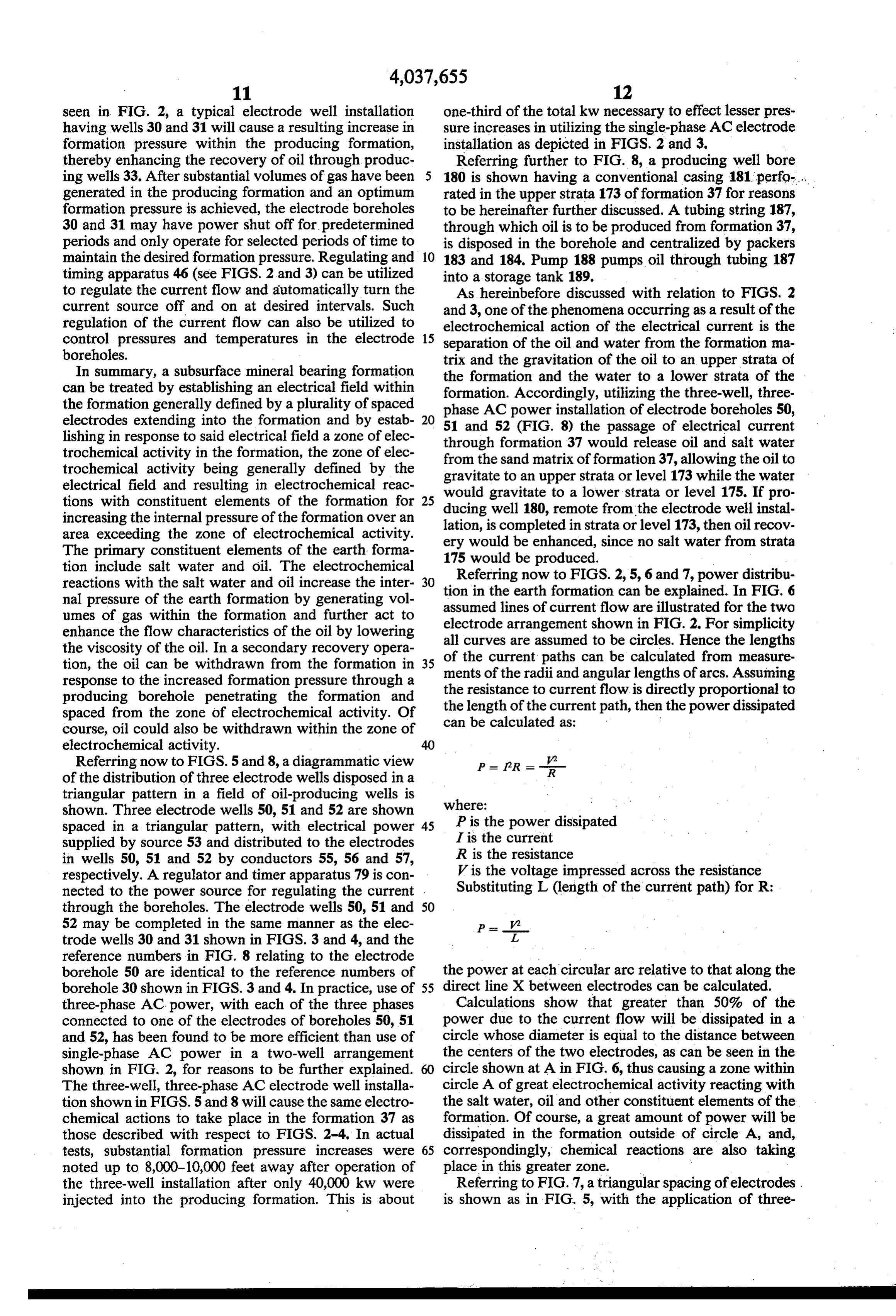
tion include salt water and oil. The electrochemical reactions with the salt water and oil increase the inter 30 Referring now to FIGS. 2, 5, 6 and 7, power distribu nal pressure of the earth formation by generating vol tion in the earth formation can be explained. In FIG. 6 assumed lines of current flow are illustrated for the two umes of gas within the formation and further act to electrode arrangement shown in FIG. 2. For simplicity enhance the flow characteristics of the oil by lowering the viscosity of the oil. In a secondary recovery opera all curves are assumed to be circles. Hence the lengths tion, the oil can be withdrawn from the formation in 35 of the current paths can be calculated from measure ments of the radii and angular lengths of arcs. Assuming response to the increased formation pressure through a the resistance to current flow is directly proportional to producing borehole penetrating the formation and the length of the current path, then the power dissipated spaced from the zone of electrochemical activity. Of can be calculated as:
course, oil could also be withdrawn within the zone of
Referring now to FIGS. 5 and 8, a diagrammatic view PR = --- of the distribution of three electrode wells disposed in a triangular pattern in a field of oil-producing wells is shown. Three electrode wells 50, 51 and 52 are shown where:
spaced in a triangular pattern, with electrical power 45 P is the power dissipated supplied by source 53 and distributed to the electrodes I is the current in wells 50, 51 and 52 by conductors 55, 56 and 57, R is the resistance respectively. A regulator and timer apparatus 79 is con V is the voltage impressed across the resistance nected to the power source for regulating the current . Substituting L (length of the current path) for R: through the boreholes. The electrode wells 50, 51 and 50 52 may be completed in the same manner as the elec P trode wells 30 and 31 shown in FIGS. 3 and 4, and the L reference numbers in FIG. 8 relating to the electrode borehole 50 are identical to the reference numbers of the power at each circular arc relative to that along the borehole 30 shown in FIGS. 3 and 4. In practice, use of 55 direct line X between electrodes can be calculated. three-phase AC power, with each of the three phases Calculations show that greater than 50% of the connected to one of the electrodes of boreholes 50, 51 power due to the current flow will be dissipated in a and 52, has been found to be more efficient than use of circle whose diameter is equal to the distance between single-phase AC power in a two-well arrangement the centers of the two electrodes, as can be seen in the shown in FIG. 2, for reasons to be further explained. 60 circle shown at A in FIG. 6, thus causing a zone within The three-well, three-phase AC electrode well installa circle A of great electrochemical activity reacting with tion shown in FIGS. 5 and 8 will cause the same electro the salt water, oil and other constituent elements of the chemical actions to take place in the formation 37 as formation. Of course, a great amount of power will be those described with respect to FIGS. 2-4. In actual dissipated in the formation outside of circle A, and, tests, substantial formation pressure increases were 65 correspondingly, chemical reactions are also taking noted up to 8,000-10,000 feet away after operation of place in this greater zone. X the three-well installation after only 40,000 kw were Referring to FIG. 7, a triangular spacing of electrodes. injected into the producing formation. This is about is shown as in FIG. 5, with the application of three
Page 14
phase AC current to the three electrode wells. Here ally perforated into the oil-bearing formation 61 by three overlapping circles B, C and D are shown as the means of perforations 63. A first tubing string 66 is greater than 50% power dissipation zones between each suspended within the insulating casing 58 and extends of the three wells. As can be seen by reference to FIG. into the steel casing section 62, terminating just above 6, the three-well, three-phase arrangement treats over the lower end of steel casing 62. Tubing string 66 is twice the area that can be treated by a single installation centralized within the borehole 50 by means of a packer of two wells. In addition, the overlapping zones of the 65 which is set just below the joint 78 of the insulated power distribution circles may enhance the electro casing 58 and steel casing section 62, for purposes chemical activity in those areas, thereby enhancing the which will be hereinafter further described. A second results obtained. In field testing the spacing between the 10 tubing string 77 is also suspended within casing 58, two-well arrangement shown in FIG. 2 was 100 feet spaced from tubing string 66, and terminates just above while the three-well pattern shown in FIG. 5 utilized a packer 65.
200-foot spacing. From comparisons of FIGS. 6 and 7, Casing 58 is sealed by means of a flanged cap or head it can be seen that the area of formation treated by the 59 through which the tubing strings 66 and 77 project. electrical field and the established electrochemical zone 15 Tubing string 66 acts as the electrode for the electrode of activity will be much larger than the area created by well and is energized by means of electrical power from a two-well arrangement, and taking into account the a source such as source 53 through conductor 55, as increased spacing in the three-well test, the power dis shown in FIG. 5, or from source 32 as shown in FIG. 3. tribution may have been increased by a factor of three As previously discussed, the heating action of the or four or more. This can reasonably explain why in 20 electrical current passing through the salt water in the actual field testing, as hereinabove described, the three oil-bearing formation causes an increase of temperature well, three-phase AC installation obtained increased within the well bore. The temperatures in the immedi formation pressures over a larger reservoir area with ate vicinity of the electrode, and particularly within about a third of the power required in the two-well steel casing section 62 and in the salt water surrounding single-phase AC test. 25 tubing string 66, acting as the electrode, can become
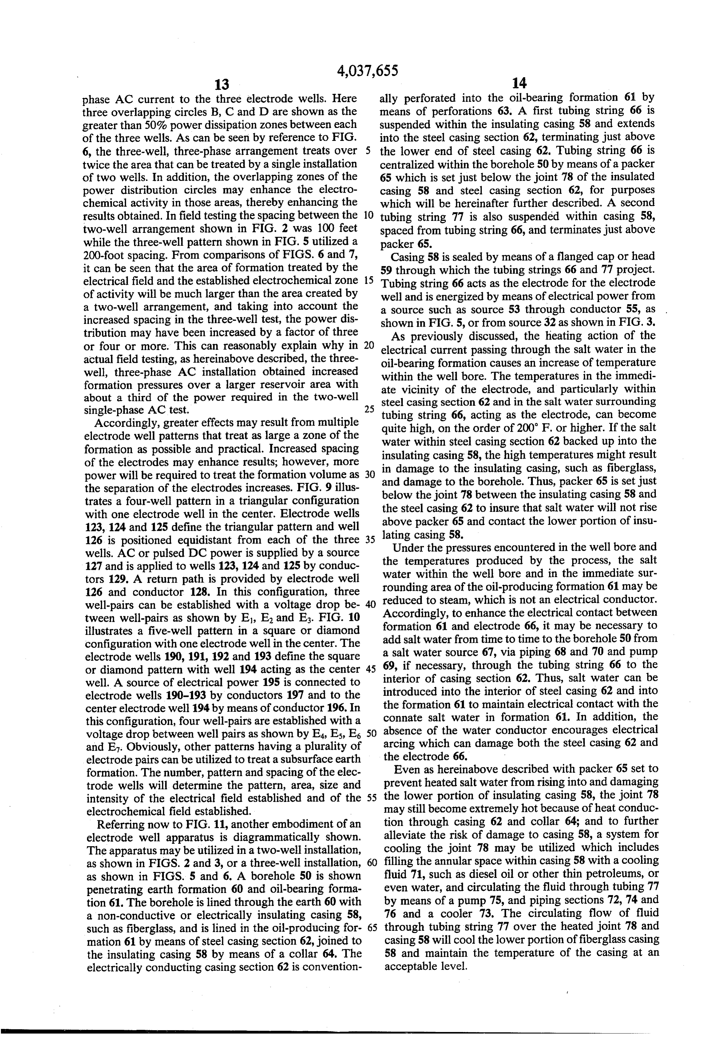
Accordingly, greater effects may result from multiple quite electrode well patterns that treat as large a zone of the waterhigh, on the order of 200 F. or higher. If the salt within steel casing section 62 backed up into the formation as possible and practical. Increased spacing insulating casing 58, the high temperatures might result of the electrodes may enhance results; however, more in damage to the insulating casing, such as fiberglass, power will be required to treat the formation volume as 30 and damage to the borehole. Thus, packer 65 is set just the separation of the electrodes increases. FIG. 9 illus below trates a four-well pattern in a triangular configuration the steelthecasing joint 78 between the insulating casing 58 and 62 to insure that salt water will not rise with one electrode well in the center. Electrode wells 123, 124 and 125 define the triangular pattern and well latingabove packer 65 and contact the lower portion of insu 126 is positioned equidistant from each of the three 35 casing 58.
wells. AC or pulsed DC power is supplied by a source theUnder the pressures encountered in the well bore and 127 and is applied to wells 123, 124 and 125 by conduc watertemperatures within the produced by the process, the salt well bore and in the immediate sur tors 129. A return path is provided by electrode well rounding area of the oil-producing formation 61 may be 126 and conductor 128. In this configuration, three reduced to steam, which is not an electrical conductor. well-pairs can be established with a voltage drop be 40 tween well-pairs as shown by E, E, and E. FIG. 10 Accordingly, to enhance the electrical contact between illustrates a five-well pattern in a square or diamond formation 61 and electrode 66, it may be necessary to configuration with one electrode well in the center. The add salt water from time to time to the borehole 50 from electrode wells 190, 191, 192 and 193 define the square a69,saltif water source 67, via piping 68 and 70 and pump necessary, through the tubing string 66 to the or diamond pattern with well 194 acting as the center 45 well. A source of electrical power 195 is connected to interior of casing section 62. Thus, salt water can be electrode wells 190-193 by conductors 197 and to the introduced into the interior of steel casing 62 and into center electrode well 194 by means of conductor 196. In the formation 61 to maintain electrical contact with the this configuration, four well-pairs are established with a connate salt water in formation 61. In addition, the voltage drop between well pairs as shown by E4, Es, E6 50 absence of the water conductor encourages electrical and E. Obviously, other patterns having a plurality of arcing which can damage both the steel casing 62 and electrode pairs can be utilized to treat a subsurface earth the electrode 66.
formation. The number, pattern and spacing of the elec Even as hereinabove described with packer 65 set to trode wells will determine the pattern, area, size and prevent heated saltwater from rising into and damaging intensity of the electrical field established and of the 55 the lower portion of insulating casing 58, the joint 78 electrochemical field established. may still become extremely hot because of heat conduc Referring now to FIG. 11, another embodiment of an tion through casing 62 and collar 64; and to further electrode well apparatus is diagrammatically shown. alleviate the risk of damage to casing 58, a system for The apparatus may be utilized in a two-well installation, cooling the joint 78 may be utilized which includes as shown in FIGS. 2 and 3, or a three-well installation, filling the annular space within casing 58 with a cooling as shown in FIGS. 5 and 6. A borehole 50 is shown fluid 71, such as diesel oil or other thin petroleums, or penetrating earth formation 60 and oil-bearing forma even water, and circulating the fluid through tubing 77 tion 61. The borehole is lined through the earth 60 with by means of a pump 75, and piping sections 72, 74 and a non-conductive or electrically insulating casing 58, 76 and a cooler 73. The circulating flow of fluid such as fiberglass, and is lined in the oil-producing for 65 through tubing string 77 over the heated joint 78 and mation 61 by means of steel casing section 62, joined to casing 58 will cool the lower portion offiberglass casing the insulating casing 58 by means of a collar 64. The 58 and maintain the temperature of the casing at an electrically conducting casing section 62 is convention acceptable level.
Page 15
Referring now to FIG. 12, another embodiment of the trating the earth 164 into an earth formation or oil-bear apparatus that may be utilized as an electrode well for ing formation 165. The borehole 159 is lined with con use in two-well installations such as those shown in ventional steel casing 160 from the surface to a lower FIGS. 2 and 3, or in three-well installations as shown in point in the earth 164, and then lined with an electri FIGS. 5 and 8, is diagrammatically illustrated. A bore cally non-conducting or insulating casing section 161. hole 80 is shown penetrating an earth formation 85 into The borehole in formation 165 is lined with an electri an oil-producing formation 86. The borehole 80 is lined cally conducting casing 162. Collars 163 couple casing with a non-conductive or insulating casing 81, prefer sections 160,161 and 162 together. A fiberglass or other ably fiberglass casing, through the earth formation 85 electrically insulating tubing 167 is suspended in bore and is lined in the oil-producing formation 86 by means 10 hole 159 and centralized and supported by packer 166. of a steel casing section 83. Steel casing section 83 is Packer 166 also seals the annular space between tubing conventionally completed utilizing perforations 89 into 167 and casing section 161 for purposes to be hereinafter the oil-producing formation 86. A string of tubing 87 of further explained. Casing 162 has a plurality of perfora smaller diameter than casing 81 is concentrically sus tions 169 displaced therein into the formation 165. pended within casing 81 to a point approximating the 15 An electrode 168 of suitable material is disposed con joinder of the earth formation 85 and the oil-producing centrically within tubing string 167 down into forma formation 86. Tubing 87 may either be conventional tion 165. An insulated head 170 seals casing 160 around steel tubing or may be an insulated or non-conductive tubing 167, and a suitable head seals tubing 167 around tubing. A string of suitable tubing 88 is concentrically electrode 168. Electrical power from a suitable source is suspended within tubing 87 and projects into the inter 20 applied to electrode 168 via conductor 171. Piping con ior of steel casing section 83 to act as an electrode and duit 172 is connected with the interior of tubing 167 for to provide means of adding salt water to the formation, introducing salt water into the borehole, if necessary, as if necessary, as previously described with regard to the hereinabove described in connection with the previous apparatus shown in FIG. 11. Casing 81 is closed with a embodiments.
cap 82, and tubing 87 is appropriately sealed to tubing 25 In this embodiment, the bore hole is fully insulated 88. Packers 91 and 92 are disposed between casing sec with electrically insulating casing. The purpose of the tions 83, the end of tubing 87, and tubing 88 for central fully insulated casing of previous embodiments is to izing and sealing the casing section 83 from the cham insulate the electrode from the earth structure for pre bers created by insulated casing 81 and the tubing 87, as venting a direct current path between the electrode and will be hereinafter further described. 30 the earth structure overlying the oil-bearing formation. Tubing 88 becomes an electrode when connected by In addition, the insulation of the borehole is to prevent means of conductor 93 to an appropriate source of elec a return current path from the electrode disposed in the trical power, such as source 53, as shown in FIG. 5, or earth formation back through the borehole to said over the source of electrical power 32, as shown in FIGS. 2 lying earth structure. In the embodiment of FIG. 13, a and 3. A salt water tank94 is connected to a pump 96 by 35 direct current path from the earth structure 164 is pre means of piping 95, the pump in turn being connected to vented by insulating tubing 167 and can be enhanced by tubing string 88 by means of piping 87 for providing a filling the annulus surrounding tubing 167 with an insu means for pumping salt water into the interior of steel lating fluid such as oil 176. If insulating casing section casing section 83 and thence into the formation 86 for 161 is of sufficient length, a return current path from the the reasons hereinabove described with regard to the 40 electrode 168 in formation 165 will be effectively bro apparatus shown in FIG. 11. ken, thereby effectively insulating electrode 168 from a Tubing 87 has perforations 90 completed just above return current path through borehole 159 into earth the area where packers 91 and 92 have been set for structure 164. This isolates the electrical current in providing communication with the interior of tubing 87 formation 165 as previously described. and the interior of casing 81. Cooling fluid 100 is intro 45 During operation of the electrode well, formation duced into the interior annular space of tubing 87, and fluids will tend to back up into tubing 167, exerting can then be circulated through tubing 87, through per substantial pressures on the interior of the tubing, and forations 90, and into the annular space of casing 81 to the addition of oil 176 in the casing annulus can also cause the fluid to flow over the joint between insulating help equalize this pressure on the insulating tubing. casing 81 and steel casing section 83 to cool the lower 50 Control of the current flow through electrode 168 and portion of casing 81 for the purposes hereinabove de formation 165 for controlling pressure and temperature scribed with regard to the apparatus shown in FIG. 11. can be achieved as hereinbefore described by appropri Fluid from the interior of casing 81 will be circulated ate regulation and/or timing equipment. through piping 101 to a cooler 102, and then piped via In FIG. 14 a simple embodiment of apparatus for piping 103 to pump 104, where the fluid is transported 55 equipping an electrode well is shown. Borehole 200 is through piping 105 to the interior annular space 98 of shown penetrating earth strata 206 and oil-bearing earth tubing 87. The cool fluid travels down the annular space formation 207. An insulated cable 202 having an electri 98 within tubing 87, out through perforations 90, over cal insulating jacket or cover 203 and a conductor 204 is the lower portion of the insulated casing 81, and returns disposed in the borehole. Insulating jacket 203 is through the annular space 99 of casing 81 to return to 60 stripped from the end of the conductor 204 to expose the cooling means 102 via piping 101. In this way, cool the conductor throughout the earth formation for act ing of the lower section of the insulating casing 81 may ing as an electrode. Gravel or other suitable porous be effected for the purposes hereinabove described. material is packed around exposed conductor 204 in the Referring to FIG. 13, yet another apparatus embodi borehole portion extending into the formation 207 to ment for equipping a well bore is shown. The apparatus 65 permit the electrode to have communication with for of FIG. 13 could be utilized in a two-well installation mation fluids. The borehole above formation 207 can shown in FIGS. 2 and 3, or in a three-well installation then be filled with insulating cement 201 to give struc- . shown in FIGS. 5 and 8. Aborehole 159 is shown pene tural support to cable 202 and to support the borehole
Page 16
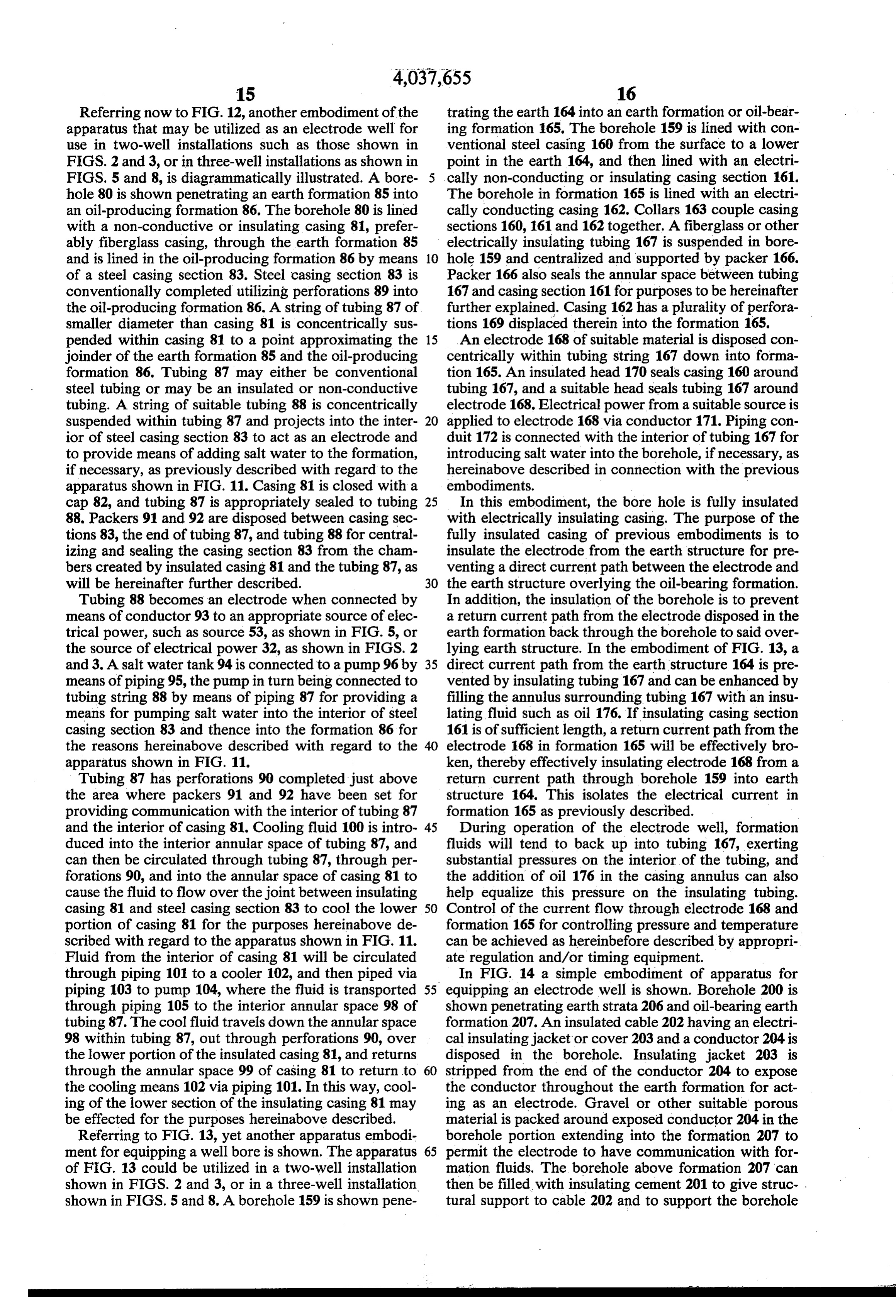
without having to set casing. The upper surface end of Reso, through one leg of an assumed "delta' load com the cable 202 is connected to a suitable source of electri prising the conductive substances of the formation, cal power by means of conductor 208. Formation fluids, primarily salt water, represented by resistor R1, and such as salt water and oil, will flow through the porous then through conductor 56. Assuming a balanced three gravel 205 and make contact with electrode 204 for phase power source and a balanced "load' (the earth establishing the electrical field in the formation 207. formation) then:
Referring now to FIGS. 5, 8 and 15, a three-electrode well installation, as shown in FIG. 5, could be effec V = IeReso + Resi -- IR tively patterned as shown in FIG. 15 to progressively cover an increasingly larger area and thereby both heat 10 but, since an increased area of the oil-bearing formation and stim I = V3i ulate gas production in the formation over a much wider area. In FIG. 15, three electrode wells 110 could V = v31, Rio + V3.I.R.: + 1,R, be drilled and completed in a triangular pattern shown as pattern 111. This installation could be utilized for a 15 predetermined period of time, and then by drilling an V = I. (N3 R+ N3R. -- R) other electrode well. 110, a second triangular pattern V, 112 could be accomplished and operated for a second I as memn predetermined period of time. It is possible to exhaust \s (Riso + Res) + Ri some of the formation fluids in the area defined by the 20 electrode well bores. However, tests demonstrate that However, in actual practice the "delta' load repre relocation of the electrode pattern provides new forma senting the oil-bearing formation may not be balanced tion fluids and also moves new fluids to old areas. By due to geological variations, and I in the various legs of drilling additional electrode wells 110, a series of triang the "delta' system load then would not be balanced and ular patterns 113-122 could be accomplished, thus dis 25 the current, I, through R1, R2 and R3 would be tributing the electrical current over a broad reservoir unequal. While this is true, loads can be balanced in the area. The gas production in the oil-bearing formation generator by creating more resistance in the surface would be enhanced, and the thermal action of the elec cables, or by changing the shape of the pattern to fit trical current would be distributed over a much wider resistance requirements.
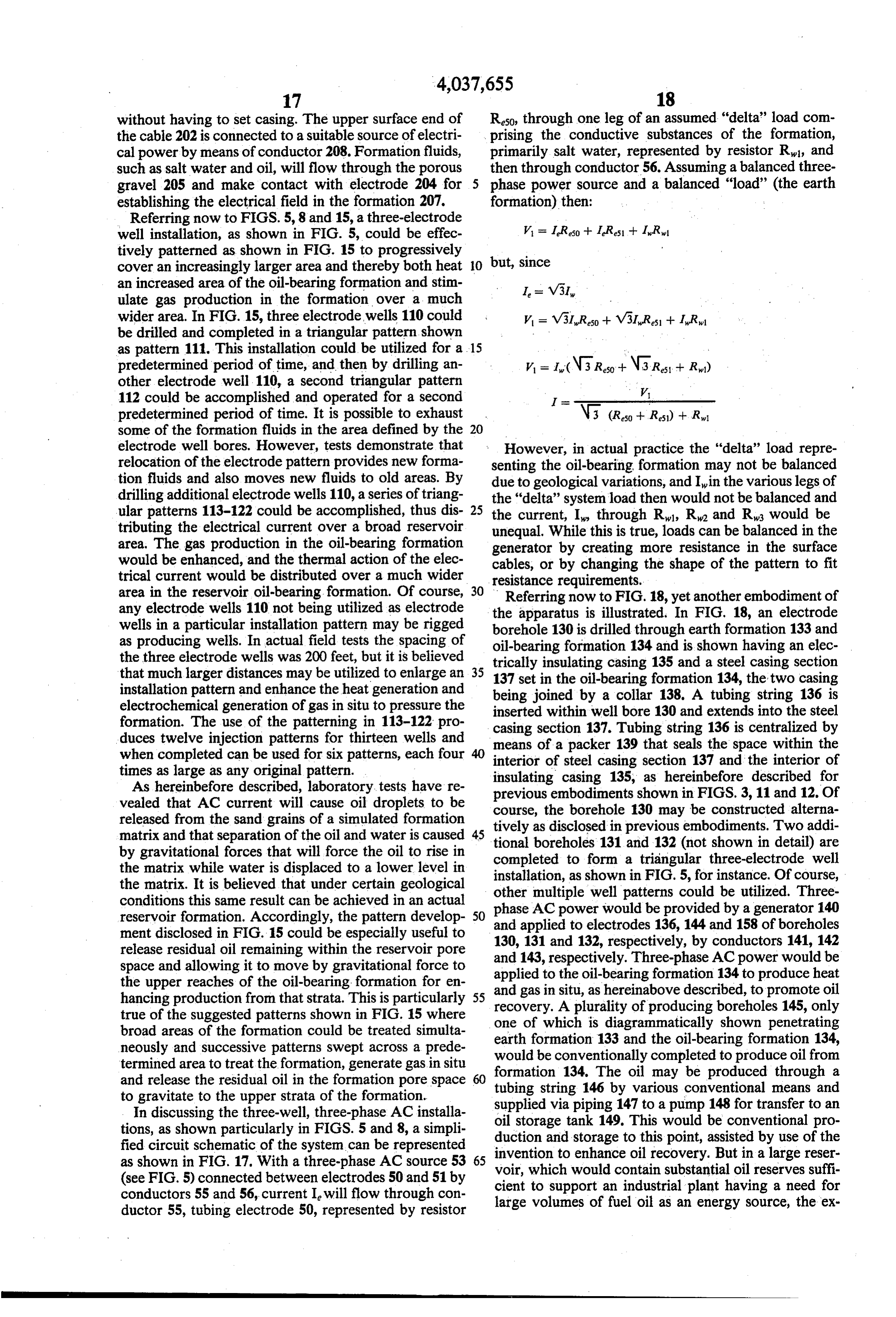
area in the reservoir oil-bearing formation. Of course, 30 Referring now to FIG. 18, yet another embodiment of any electrode wells 110 not being utilized as electrode the apparatus is illustrated. In FIG. 18, an electrode wells in a particular installation pattern may be rigged borehole 130 is drilled through earth formation 133 and as producing wells. In actual field tests the spacing of oil-bearing formation 134 and is shown having an elec the three electrode wells was 200 feet, but it is believed trically insulating casing 135 and a steel casing section that much larger distances may be utilized to enlarge an 35 137 set in the oil-bearing formation 134, the two casing installation pattern and enhance the heat generation and being joined by a collar 138. A tubing string 136 is electrochemical generation of gas in situ to pressure the inserted within well bore 130 and extends into the steel formation. The use of the patterning in 113-122 pro casing section 137. Tubing string 136 is centralized by duces twelve injection patterns for thirteen wells and means of a packer 139 that seals the space within the when completed can be used for six patterns, each four interior of steel casing section 137 and the interior of times as large as any original pattern. insulating casing 135, as hereinbefore described for As hereinbefore described, laboratory. tests have re previous embodiments shown in FIGS. 3, 11 and 12. Of vealed that AC current will cause oil droplets to be course, the borehole 130 may be constructed alterna released from the sand grains of a simulated formation tively as disclosed in previous embodiments. Two addi matrix and that separation of the oil and water is caused 45 tional boreholes 131 and 132 (not shown in detail) are by gravitational forces that will force the oil to rise in completed to form a triangular three-electrode well the matrix while water is displaced to a lower level in installation, as shown in FIG. 5, for instance. Of course, the matrix. It is believed that under certain geological other multiple well patterns could be utilized. Three conditions this same result can be achieved in an actual reservoir formation. Accordingly, the pattern develop 50 phase AC power would be provided by a generator 140 ment disclosed in FIG. 15 could be especially useful to 130, 131 andto132, and applied electrodes 136, 144 and 158 of boreholes respectively, by conductors 141, 142 release residual oil remaining within the reservoir pore and 143, respectively. Three-phase AC power would be space and allowing it to move by gravitational force to applied to the oil-bearing formation 134 to produce heat the upper reaches of the oil-bearing formation for en and gas in situ, as hereinabove described, to promote oil hancing production from that strata. This is particularly 55 recovery. A plurality of producing true of the suggested patterns shown in FIG. 15 where one of which is diagrammatically boreholes 145, only shown penetrating broad areas of the formation could be treated simulta neously and successive patterns swept across a prede would earth formation 133 and the oil-bearing formation 134, be conventionally completed to produce oil from termined area to treat the formation, generate gas in situ formation and release the residual oil in the formation pore space tubing string134. The oil may be produced through a to gravitate to the upper strata of the formation. 146 by various conventional means and In discussing the three-well, three-phase AC installa supplied via piping 147 to a pump 148 for transfer to an tions, as shown particularly in FIGS. 5 and 8, a simpli oil storage tank 149. This would be conventional pro duction and storage to this point, assisted by use of the fied circuit schematic of the system can be represented invention as shown in FIG. 17. With a three-phase AC source 53 65 voir, whichto would enhance oil recovery. But in a large reser (see FIG. 5) connected between electrodes 50 and 51 by cient to support ancontain substantial oil reserves suffi conductors 55 and 56, current I will flow through con large volumes of fuel oil as anplant industrial having a need for energy source, the ex ductor 55, tubing electrode 50, represented by resistor
Page 17
haust or "flue' gases from such a plant could be utilized In addition, there are environmental benefits accruing in further enhancing the production capabilities of the from the utilization of the installation and process reservoir. Assuming the industrial plant to be an electri shown in FIG. 18, since the flue gases would be re cal generating plant utilizing oil-fired turbines, the plant turned into the ground for use in enhancing recovery of could be constructed immediately adjacent the reser 5 oil and not released into the atmosphere as a pollutant. voir area for receiving the produced oil and for mini Although the present invention has heretofore been mizing the distance that the flue gases must be trans described with respect to its utility in effecting the re ported prior to use in the reservoir. This embodiment is covery of oil, it will be apparent that the concept of the described in relation to an electrical generating plant, present invention is also applicable to various other uses but other industrial plants having a high oil fuel energy O such as the removal of impurities from waste water and need and creating substantial quantities of useful ex other industrial fluids. In one such embodiment, the haust gases could, of course, be substituted. liquid to be purified is collected in a vat or other con Referring again to FIG. 18, the produced oil would tainer which is charged with a brine or other suitable be transferred from the oil storage tanks 149 to the electrolytic solution. A suitable alternating current may electric generating plant 151 by means of pumps 150 for 15 then be applied to the terminals of two electrodes which supplying the crude oil to appropriate treating means, if are immersed in a spaced apart relationship in the con necessary (not shown), to prepare the crude oil for tents of the container. Accordingly, the current passing firing the turbine generators. The oil-fired turbines through the electrolyte and between the two electrodes would generate electrical power for distribution by the will produce separation of solids from the liquid, and generating plant in the power company's power distri 20 these solids will then settle to the bottom of the con bution system. The output flue gases of the oil-fired tainer as a sludge. This same process can be used as a turbines would be collected at 152 and routed through pre-distillation step in the purification of water for ordi piping 153, pump 154 and piping 155 to a pipe or tubing nary drinking purposes, inasmuch as impurities such as 157 disposed in injection borehole 156, as shown pene iron, gypsum and magnesium oxides may be easily sepa trating the earth formation 133 and the oil-producing 25 rated out in this manner before the distillation step is formation 134. In actual operation, the injection bore performed. Combustion gases and smokes can also be hole 156 would be located in or adjacent the pattern of removed from air in this manner bypassing the polluted the three electrode wells 130, 131 and 132, although not air through a chamber containing a pair of electrodes so shown in the diagrammatic illustration of FIG. 18. adapted to be charged in this manner.
The hot pressurized flue gas introduced into the oil 30 Numerous variations and modifications may obvi bearing formation 134 through injection well 156 will ously be made in the structure and processes herein lower the viscosity of the oil and enhance its flow char described without departing from the present invention. acteristics. The flue gas from an oil-fired turbine or Accordingly, it should be clearly understood that the engine will contain carbon monoxide and carbon diox forms of the invention herein described and shown in ide as well as other gases. The carbon dioxide and car 35 the figures of the accompanying drawings are illustra bon monoxide gases, whether heated or not, will tend to tive only and are not intended to limit the scope of the combine with the oil in the producing formation, and in invention c. . so doing combine chemically with the oil to improve its What is claimed is:
flow characteristics. In addition, the flue gas will ordi 1. A method of increasing the internal pressure in a narily be hot (in the range of 800-1,000 F) and will 40 fluid-bearing earth formation, comprising the steps of act to dissolve tars and lower the viscosity of the oil. In establishing at least two spaced apart boreholes ex addition, pumping the heated flue gas back into the tending into a subsurface earth formation contain formation under pressure adds to the formation pres ing both oil and other aqueous liquids, sure, thereby enhancing the formation driving energy. disposing a separate electrical conductor in each of The flue gas will have a considerable BTU content 45 said boreholes and into electrical contact with said since not all of the hydrocarbons have been burned, and aqueous liquids in said formation, the long term injection of the gas into the formation will insulating both of said conductors from substantially create a reservoir of gas having considerable BTU value all earth materials adjacent said boreholes and lying that could create a source of gas for future recovery and above said subsurface earth formation to establish use as a fuel. , .. . 50 an electrical path composed of said insulated con The use of the flue gas injection process would be ductors and said formation materials extending ideally suited for use in an area where there is a large therebetween, v .. reservoir of very viscous oil or sands having tar oils of establishing an AC flow of electric current in said extremely low gravity and high viscosity that can be electrical path composed of said insulated conduc produced by the use of the invention herein described 55 tors and said formation materials lying therebe and recovered in quantities sufficient to operate an in tWeen, dustrial plant that, in turn, would generate sufficient electrochemically generating free hydrogen gas in quantities of exhaust or flue gases that could be returned said subsurface earth formation between said bore to the oil formation for the purposes hereinabove men holes as a function of current intensity in said for tioned. As an example, a 1-megawatt electrical generat mation, and ing plant could utilize 40,000 barrels of oil a day pro trapping said free hydrogen gas in said formation to duced from the oil reservoir and generate 200,000,000 increase the pressure in said formation on said oil cubic feet of gas a day for reinjection into the oil-bear therein.
ing formation. This arrangement could have particular 2. The method described in claim 1, further including economic appear to many industries dependent upon oil 65 the steps of : or natrual gas as a fuel, since natural gas is in short establishing another different borehole spaced from supply and oil may economically be recovered by use of said boreholes and also extending into said subsur-. the electrical process. face earth formation, and
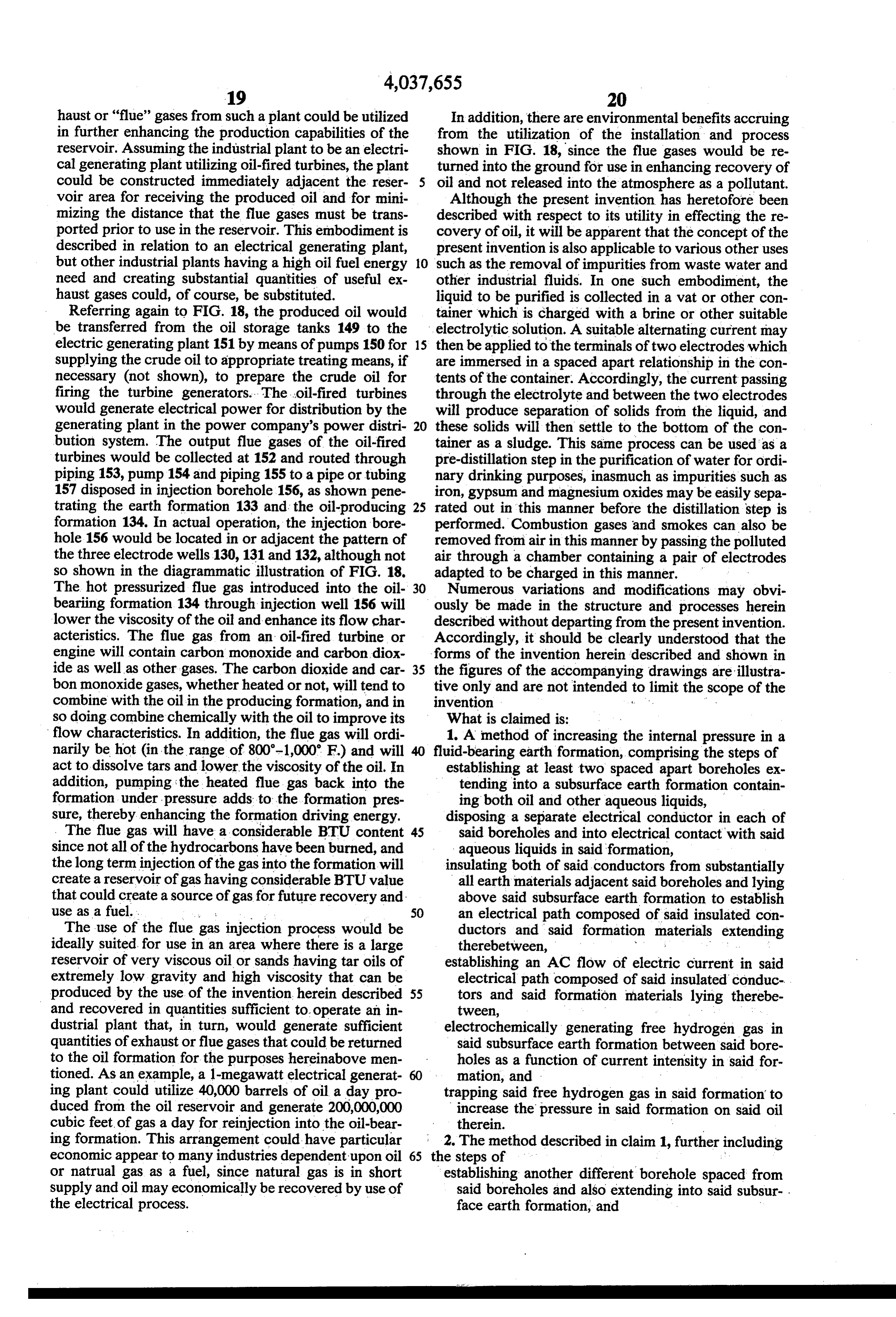
Page 18
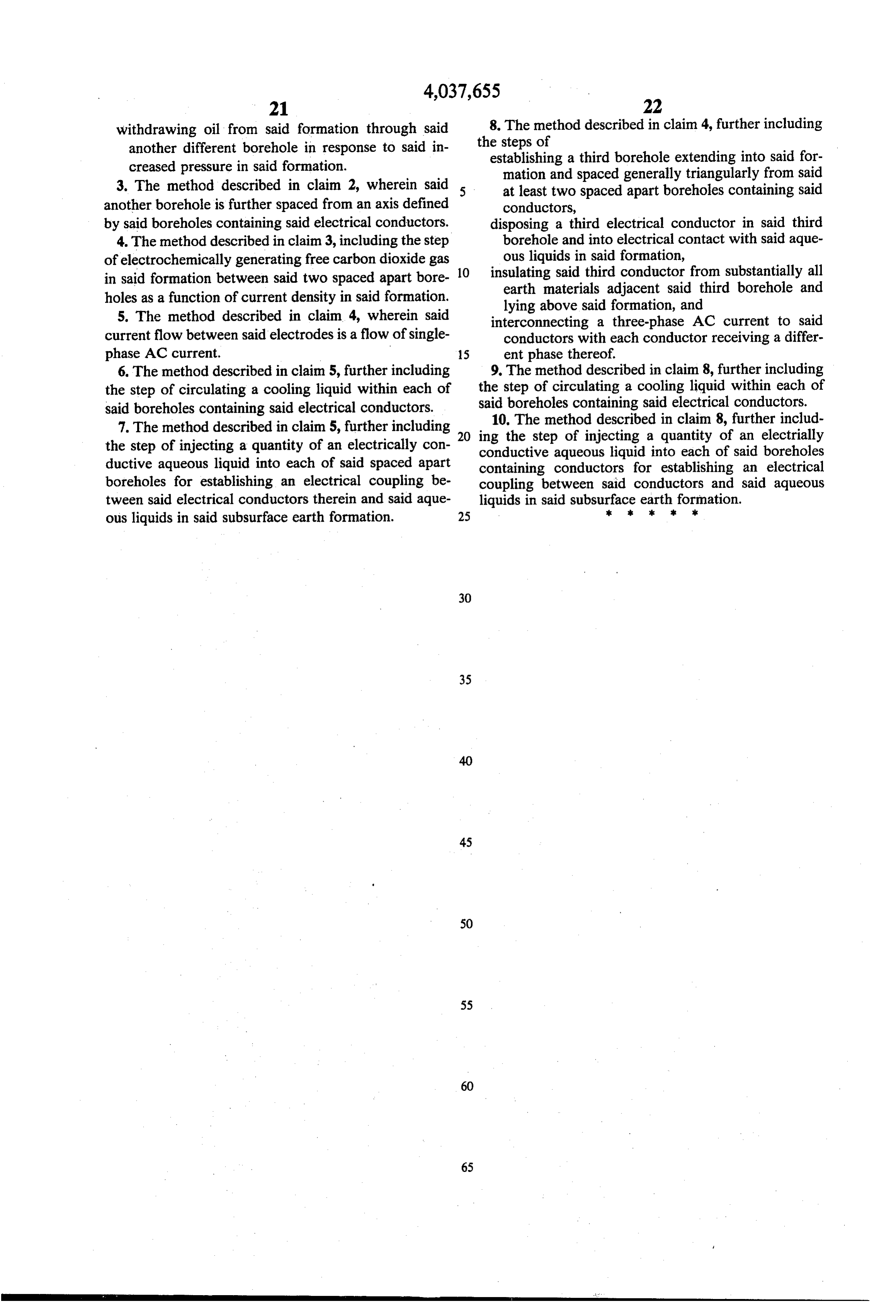
withdrawing oil from said formation through said 8. The method described in claim 4, further including another different borehole in response to said in the steps of creased pressure in said formation. establishing a third borehole extending into said for mation and spaced generally triangularly from said 3. The method described in claim 2, wherein said at least two spaced apart boreholes containing said another borehole is further spaced from an axis defined conductors, by said boreholes containing said electrical conductors. disposing a third electrical conductor in said third 4. The method described in claim 3, including the step borehole and into electrical contact with said aque of electrochemically generating free carbon dioxide gas ous liquids in said formation, 10 insulating said third conductor from substantially all in said formation between said two spaced apart bore earth materials adjacent said third borehole and holes as a function of current density in said formation. lying above said formation, and 5. The method described in claim 4, wherein said interconnecting a three-phase AC current to said current flow between said electrodes is a flow of single conductors with each conductor receiving a differ phase AC current. 15 ent phase thereof.
6. The method described in claim 5, further including 9. The method described in claim 8, further including the step of circulating a cooling liquid within each of the step of circulating a cooling liquid within each of said boreholes containing said electrical conductors. said boreholes containing said electrical conductors. 7. The method described in claim 5, further including 20 ing10.the
The method described in claim 8, further includ step of injecting a quantity of an electrially the step of injecting a quantity of an electrically con conductive aqueous liquid into each of said boreholes ductive aqueous liquid into each of said spaced apart containing conductors for establishing an electrical boreholes for establishing an electrical coupling be coupling between said conductors and said aqueous tween said electrical conductors therein and said aque liquids in said subsurface k k earth
formation.
ous liquids in said subsurface earth formation. 25
Page 19
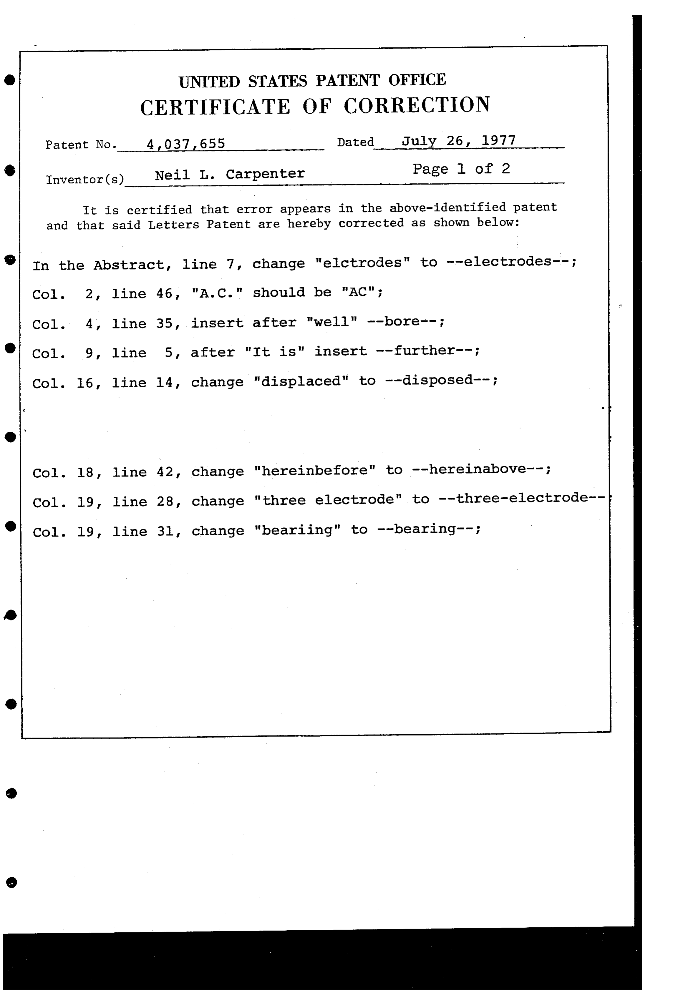
O UNITED STATES PATENT OFFICE
CERTIFICATE OF CORRECTION
Patent No. 4 O37 655 Dated July 26, 1977
O Inventor(s) Neil L. Carpenter Page l of 2 It is certified that error appears in the above-identified patent and that said Letters Patent are hereby corrected as shown below:
O In the Abstract, line 7, change "elctrodes" to --electrodes--;
35, insert after "well" --bore--
l4, change "displaced" to --disposed--;
Page 20
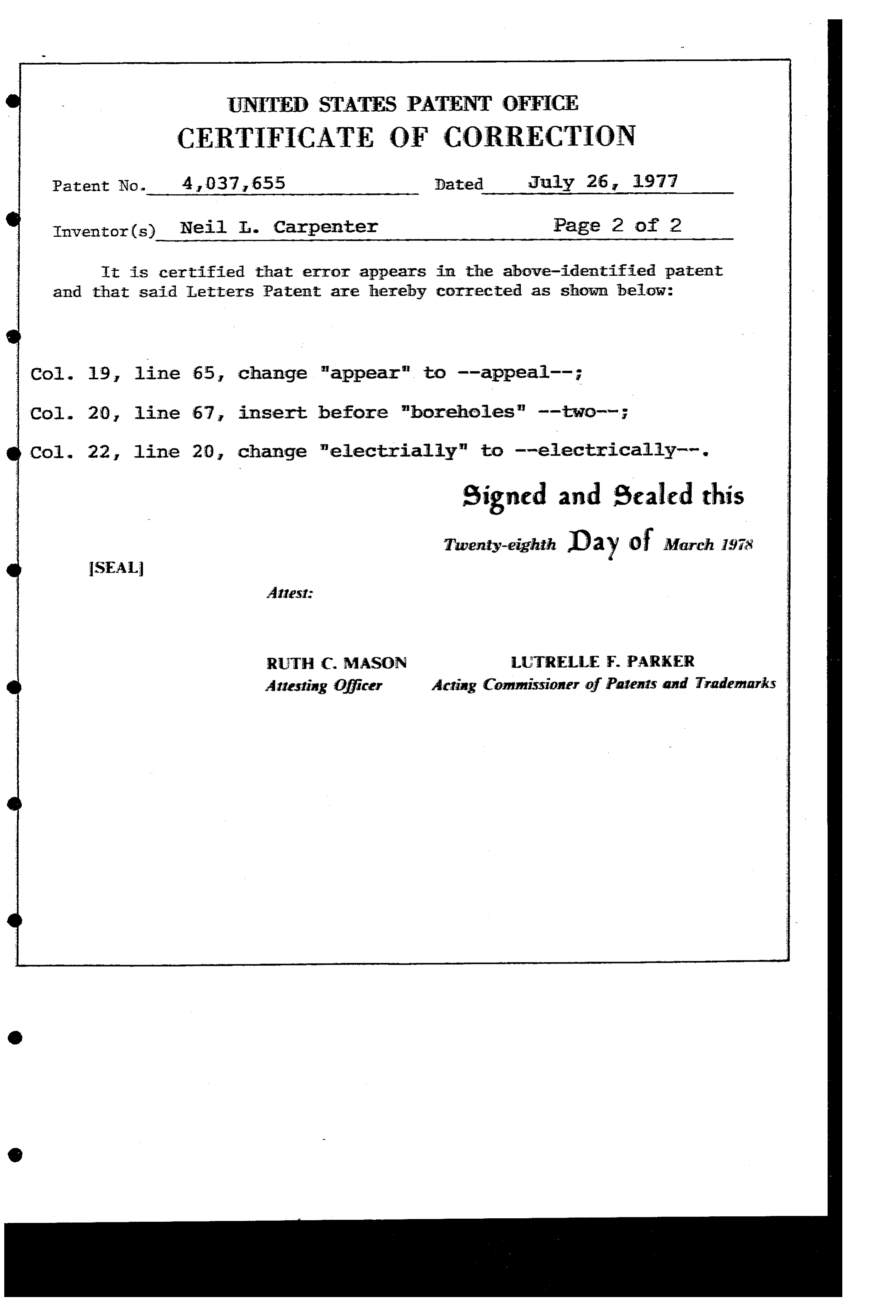
UNITED STATES PATENT OFFICE
CERTIFICATE OF CORRECTION
Patent No. 4,037, 655 Dated July 26, 1977
Inventor(s). Neil T. Carpenter Page 2 of 2 It is certified that error appears in the above-identified patent and that said Letters Patent are hereby corrected as shown below:
19, line 65, change "appear" to --appeal-;
20 line 67, insert before "boreholes" --two-s-;
22, line 20, change "electrially" to --electrically--.
signed and sealed this
Tuventy-eighth Day of March 1978
SEAL
RUTH C. MASON LUTRELLE F. PARKER : Attesting Officer Acting Commissioner of Patents and Trademarks
Provenance
- Collection
- Cited prior art
- Original PDF
- patentimages.storage.googleapis.com →
- Filed
- 1975-10-21
- Pages
- 20
- Method
- pdftotext (the PDF's own text layer) + pdftoppm 300dpi page scans
- Source
- Google Patents bibliographic record
- Granted
- 1977-07-26
- Inventors
- Neil L. Carpenter; Electroflood Co
- Transcribed from
- patentimages.storage.googleapis.com →