patent · US3696866
Method for producing retorting channels in shale deposits
10 October 1972
Page 1 — bibliographic record
United States Patent (15) 3,696,866 Dryden (45 Oct. 10, 1972 54 METHOD FOR PRODUCING 56) References Cited
RETORTING CHANNELS IN SHALE
DEPOSITS UNITED STATES PATENTS s r 3,103,975 9/1963 Hanson.................. 166/248 X 72) Inventor: Julian R. Dryden, Laramie, Wyo. 2,994,377 8/1961 Tanthan................. 166/260 X 73 Assignee: The United States of America as 3,106,244 10/1963 Parker....................... 66/248 represented by the Secretary of the 3,428,125 2/1969 Parker....................... 166/248 Interior 2,795,279 6/1957 Sarapuu................. 166/248 3,21 1,220 10/1965 Sarapuu..................... 166/248 22) Filed: Jan. 27, 1971 3,137,347 6/1964 Parker....................... 166/248 (21) Appl. No.: 110,090 w
Primary Examiner-Robert L. Wolfe
Attorney-Ernest S. Cohen and Albert A. Kashinski 52 U.S. Cl................................................... 166/248 57 ABSTRACT 51 int. Cl. .......... a a e o os o o in o o o a a E21b 43100 58) Field of Search...... 166/248,256, 261, 272,275 A method for producing in situ retorting channels in 4-s/ w as w is 166/302. subterranean shale deposits. Electro-pneumatic treat ment is used for lean shale. Additional electro-chemi cal treatment is required for rich shale.
7 Claims, 2 Drawing Figures
ELECTRICAL
VOAGE
SOURCE
YZZZZZZZZZZZ
warrrry
syssexy yarreryx
Page 2
Drawing sheet — no readable text.
Page 3
METHOD FOR PRODUCING RETORTING each wellbore in contact with the shale bed, preferably CHANNELS IN SHALE DEPOSTS vertically aligned with a single bedding plane. By apply BACKGROUND OF THE INVENTION ing a high, preferably a.c., electrical voltage to the elec trodes, an electrical current is caused to flow through
While oil shale deposits include a substantial per the shale between the wellbores. Sufficient current centage of our nations mineral energy resources, com heats the shale intensely, forming a viscous, molten pared to oil sands the recovery of shale-borne oil is dif fluid core. This fluid core is forced to flow out of the ficult and expensive. Open pit recovery techniques are surrounding shale by injecting high pressure gas into at present the most highly developed for practical oil one of the wellbores. An open retorting channel results. shale utilization, but these techniques are undesirable 10 For rich shales, additional treatment is required since they are inefficient and permanently mar the between the electric heating and gas injecting steps. landscape. In situ recovery techniques, because they Conducting cores formed in rich shale are not suffi are more efficient and less destructive, are a more ac ciently molten for immediate removal by high pressure ceptable alternative. gas injection. Before removal, the rich shale core must One method for in situ recovery of oil from subter 15 be reduced to lean shale by electro-chemical reaction. ranean shale deposits is described in U.S. Pat. No. After electrically forming a conducting core by the 3,106,244, issued to H. W. Parker. Into a pre-formed process used for lean shale, one electrode is removed fracture system, Parker injects air to advance a direct from contact with the shale bed. An electrolytic solu drive combustion zone which is generated by simul 20 tion is poured into the vacant wellbore and an acid-re taneously applying high voltage electricity. Hydrocar sistant electrode suspended within it. A high d.c. volt bons are produced from the shale adjacent to the frac age is applied between the acid-resistant electrode and tures. the other electrode, causing electrolysis and forming Another method useful for in situ recovery is free oxygen where the conducting carbon core inter described in U.S. Pat. No. 3,103,975, issued to A. W. 25 sects the solution. Using sufficient voltage to cause a Hanson. By electrical and chemical treatment of an oil high electric current with intense heating and arcing, shale bed, Hanson enlarges fractures between spaced combustion of organic materials results in the presence wellbores. Once a fracture has been produced between of the oxygen. Vigorous percolation of the electrolyte the wellbores, Hanson floods the fracture with an elec in the combustion zone renews the spent electrolyte trolyte through which an electric current, preferably 30 while removing the combustion products. Application a.c., is passed. Chemical and thermal reaction of the of the electrical voltage continues until the combustion electrolyte with the walls of the fracture causes crum bling and sloughing, enlarging the communicating zone has completely penetrated the conducting path between the wellbores.
passageway between the wellbores. Sometimes this electro-chemical treatment alone is The methods of both parker and Hanson require 35 sufficient to create a usable retorting channel. Often, fracturing of the oil shale bed with high fluid fracturing however, the resulting lean shale core requires addi pressures. To create fractures, the entire body of shale tional electro-pneumatic treatment to form a usable must be moved by the pressure applied. The power ap channel. This additional treatment follows the steps plied must be proportional to the weight of the over described above for lean shale. bearing formation. For deep fracturing, power require 40 Therefore, ments are excessive. To obviate the need for fracturing for producing one object of this invention is a method retorting channels in subterranean shale.
in in situ recovery of oil from shale deposits, this inven Another object of this invention is an electro-pneu tion was made.
matic method for producing retorting channels in lean
My invention is a method for in situ production of re calAnother method object of the invention is an electro-chemi for producing retorting channels in rich torting channels in oil shale. Electro-pneumatic treat shale.
ment is used in lean shale. Additional electro-chemical treatment is applied to rich shale. In many respects, 50 in These the and other objects of this invention are evident following specification and drawing.
both forms of treatment employ similar apparatus.
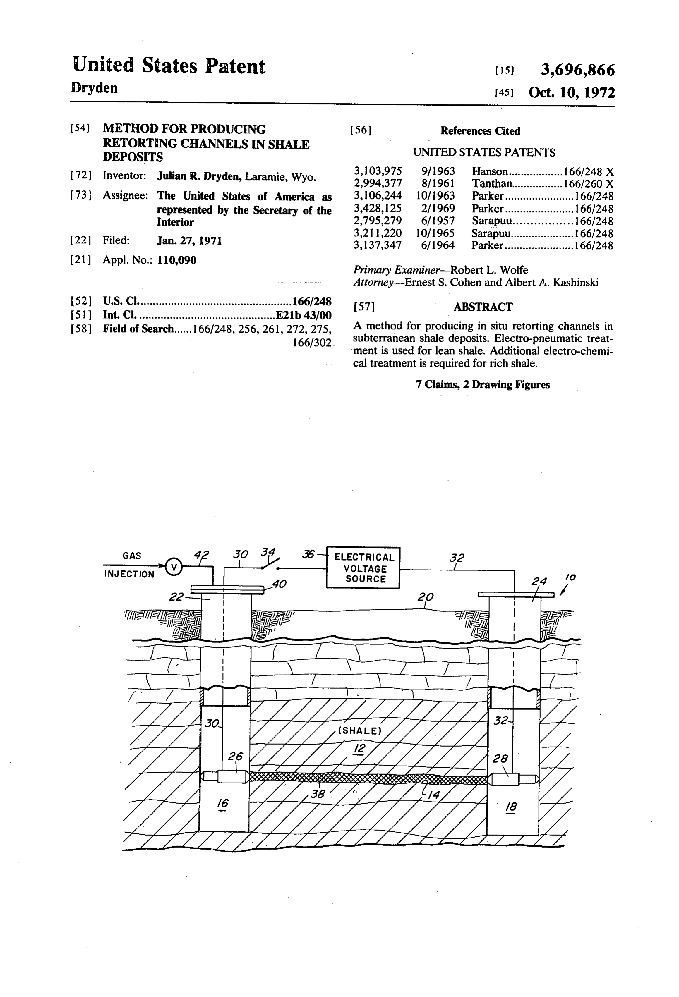
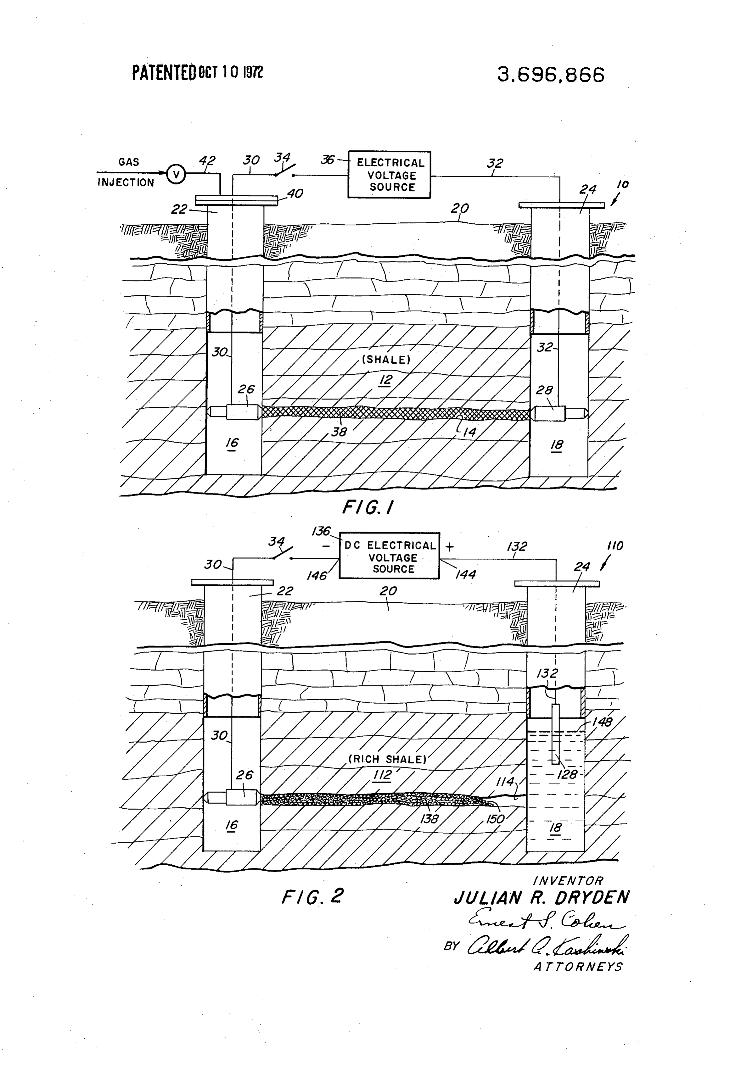
As a primary distinction from previous methods for DESCRIPTION OF THE DRAWING producing retorting channels, using my invention no at FIG. 1 shows an arrangement of apparatus for elec tempt is made to fracture the shale bed. Retorting tro-pneumatically channels are produced by actually removing material 55 terranean shale. producing retorting channels in sub from the bed between spaced wellbores without signifi FIG. 2 shows an arrangement of apparatus for elec cantly altering the strength of the surrounding forma tion. Unlike fractured channels which close up as the tro-chemically producing retorting channels in subter shale settles, channels produced by my invention have ranean shale.
little inclination to close up. Because of their relatively 60 DESCRIPTION OF THE PREFERRED large size they are less subject to plugging than frac EMBODIMENT tured channels. Since no attempt is made to fracture, no overburden need be moved, and power require A stratified geological formation 10 with an oil shale ments are independent of the depth of the channels bed 12 is shown in cross-section in FIG. 1. For produc below the surface. ing a horizontal retorting channel 14 through the sub For electro-pneumatically producing retorting chan 65 terranean bed, two spaced wellbores 16 and 18 extend nels in lean shale, two spaced wellbores are sunk into a downward from the surface 20 to deep within the for subterranean shale bed. An electrode is inserted into mation. The wellbores penetrate the shale bed to a
Page 4
depth beyond the optimum level for producing and Numerous designs are suitable for electrodes 26 and operating the retorting channel. Open ended tubular 28. Important design criteria for the electrodes include casings 22-24 line the walls of each wellbore, prevent firm contact with the shale bed and a small contact ing collapse of softer overburden into the underlying area. Firm contact is required for electrical continuity. portion of the bore. A small contact area prevents dissipation of electrical In electrical contact with a wall of each wellbore power and assures ample space for discharging molten 16-18, expandable, conductive electrodes 26-28 de material past the low pressure electrode. In addition, pend from insulated electrical conductors 30-32. the electrodes should be resistant to both heat and elec Through an intermediate on-off switch 34, conductor 10 trical arcing resulting from high potential operation. 30 connects electrode 26 to one output terminal of an Air is a suitable gas for injection into well 16. Varia electrical voltage source 36. Conductor 32 connects ble pressures are satisfactory, but rapid injection is electrode 28 to the other output terminal of the source. required, so gas pressure must remain sufficiently high When switch 34 closes, an electrical voltage appears to support molten flow once it has begun. With high gas between the two electrodes situated deep within the 15 pressure the molten slag is prevented from solidifying wellbores. Depending upon the electrical resistance of at the effluent end of the channel 38. The molten the particular shale bed 12, a sufficiently high voltage materials discharge as finely divided particles, harden between the electrodes causes a powerful electrical ing into tiny pellets with minimum tendency to plug the current to flow through the bed. The electrical current wellbore 18.
heats the path between the electrodes, forming a 20 Placing electrodes 26, and 28 in contact with the charred conducting core 38 within the surrounding same bedding plane in shale bed 12 minimizes electri shale. By removing this charred core, an open retorting cal resistance along the conducting path and insures channel is formed. Depending upon whether the shale optimum efficiency. For best results, wellbores 16 and is rich or lean in oil content, the removal process in 18 are analyzed by coring during drilling and the elec cludes a somewhat different series of steps. 25 trodes placed in a bedding plane of lowest oil content. If the shale bed 12 is lean in oil content, the charred Laboratory tests indicate that although charred slag core 38 is removed by pressurized gas. For lean shale, cores are formed in most shales, melting is limited to continued application of electrical current melts the shales containing less than about twenty gallons of oil core, forming a very viscous stream of molten liquid. perton. In richer shales the electrical current causes in slag within the surrounding bed of impervious shale. In 30 sufficient heating for treatment in this manner. For rich jecting pressurized gas into one wellbore while main shale beds, an alternate operation is required. taining the other wellbore at atmospheric pressure As described above treating oil shale, whether lean forces the molten stream to flow out of the retorting or rich, with sufficient electric current causes a charred channel. This operation is performed in the following 35 carbon core. Two general core types result. Lean shales ac. form slag cores which ultimately melt from sufficient On the surface end of casing 22 a cap 40, as shown in electrically generated heat. Slag cores formed in rich FIG. 1, seals wellbore 16 to form a closed subterranean shales, however, remain relatively solid regardless of chamber. Through a sealed opening in the cap, a supply the heat applied. Since the organic oil content of a rich conduit 42 injects, high pressure gas into the sealed 40 shale core often exceeds one-third the raw - shale wellbore. Depending upon the physical resistance of volume, the core permeability can be increased by the particular lean shale bed 12, a sufficiently high removing the oil from the residual carbon and slag by pressure gradient between wellbores 16 and 18 forces an electro-chemical process. Cores with high slag con the viscous stream to flow along the heated path and tent become essentially lean shale once the oil is into wellbore 18 in a manner analogous to fluid flow 45 removed. Often the resulting core is sufficiently perme within a pipe. When the pressure gradient lowers able for use as a retorting channel without additional rapidly, evidencing retorting channel breakthrough, treatment. In many cases, however, the slag core result electrical switch 34 is opened and gas injection ing from electro-chemical treatment is an impervious stopped. The retorting channel is then available for in as indigenous lean shale. These cases require additional situ oil recovery by established procedures. 50 treatment, using the above described method for Both a.c. and d.c. electrical voltage sources are suita producing retorting channels in lean shale. ble for producing conducting cores and melting oil An arrangement for electro-chemically removing the shale in this manner. A.c. is preferred since shale offers oil from electro-thermally generated carbon cores in less resistance to breakdown from an a.c. than from a rich shale beds is shown in FIG. 2. Elements common d.c. voltage. Since shale is often a good insulator, initial 55 to both FIGS. 1 and 2 have identical two digit reference electrical breakdown usually requires extreme volt numerals. Unique elements in FIG. 2 have three digit ages. In actual tests, sources producing as high as reference numerals. In this Figure a geological forma 22,400 volts have been used, although a.c, voltages in tion with a carbon core 138 penetrating a stratum of the range of 3,000 volts have produced successful 60 rich oil shale 112 is shown in cross-section. The carbon results. Higher voltage requirements are expected for core is first produced in the rich shale bed in the many in situ operations. As current flow begins, re manner shown and described with reference to FIG. 1. sistance decreases sharply so voltage requirements After the core is produced, as evidenced by a decrease diminish. Subsequent current loads are governed by the in electrical resistance between the electrodes, elec power required to char the core 38 and maintain it in a 65 trode 28 and insulated conductor 32 are removed from molten state. Because the amount of heating is directly - wellbore 18, and replaced by a long, acid-resistant elec proportional to current flow, the core diameter trode 128, suspended by an insulated electrical con produced increases directly with current intensity. ductor 132. Conductor 132 connects electrode 128 to
Page 5
the positive output terminal 144 of a d.c. electrical predict precisely. General parameters, however, are voltage source 136, while conductor 30, through switch sufficient for establishing necessary design criteria. In 34, connects electrode 26 to the negative terminal 146. this regard, electrode 128 is preferably constructed When switch 34 closes, a d.c. electrical voltage appears from an acid-resistant material. Since hydrogen is between electrodes 26 and 128. produced adjacent to this electrode, oxidation is not a Into wellbore 18 an electrolytic solution 148, such as problem, and a carbon electrode is suitable. For dimen water or a dilute acid-water mixture, is pumped until sional purposes, in laboratory experiments a current electrode 128 is at least partially submerged. At this density of 1 ampere per square inch of submerged elec level the solution completely submerges the proximate trode area yielded satisfactory results. Dilute end of charred core 138. For improving electrical con 10 hydrocloric acid is a suitable electrolytic solution since tinuity between electrode 26 and the charred core, it is readily available and generally produces solvable plain water can be pumped into wellbore 16 if necessa chloride salts. Other dilute common acids are equally ry. When the electrical potential from d.c. source 136 satisfactory. The amount of dilution is not critical. is applied between electrodes 26 and 128, electrical 15 Voltage requirements vary greatly, depending upon continuity is completed through charred conducting the particular environment operated upon. Sufficient core 138 and electrolytic solution 148. Electrolysis of voltage is necessary to stimulate heating and percola the solution results, decomposing the water to form tion, as described above. Field tests have successfully free hydrogen at the positive electrode 128, and free employed as low as 143 volts at 5.7 amperes to cause oxygen at the electrical extension of the negative elec 20 the necessary percolation. By using adequate current trode 28 - the end of conducting carbon core 138 in flow in the initial formation of the conducting carbon contact with the electrolyte 148. path 138 a low resistance conductor results, reducing To avoid confusion regarding the labeling of electrol electro-chemical processing voltage requirements to a ysis electrodes 26 and 128 as negative and positive, minimum. During electrolysis, the amount of current respectively, please note that the electrical, rather than 25 required varies with the structure of the core. A good chemical convention for current flow is applied. Fol rule is to always exceed the maximum current used to lowing this convention, hydrogen forms at the positive form the core. Laboratory tests have successfully em electrode, and oxygen at the negative electrode.
With a negative electrical potential applied to con ployed currents of 8 to 10 ampers for cores from 1 to 2 inches in diameter.
ducting carbon core 138, pure oxygen is formed at the 30 By combining the electro-pneumatic process of FIG. intersection area 150 of the core and electrolytic solu 1 and the electro-chemical process of FIG. 2 it is possi tion 148. This free oxygen is available for combustion ble to produce retorting channels in all grades of rich of the carbonaceous material within the core. By rais and lean shales. Once the channels are produced, re ing the voltage of d.c. source 136, sufficient electrical torting proceeds according to established procedures. current is generated through core 138 to create heat 35 Because, within the bounds of these established and electrical arcing in intersection area 150. Since procedures, modifications of the electro-pneumatic submerged combustion is possible in the presence of and electro-chemical process steps will be obvious to pure oxygen, the electrolytic solution does not hinder persons of ordinary skill in the art, the scope of this in oxidation, and a fire front moves forward until the en vention should not be limited by the above description, tire core is burned. When combustion is completed but only by the following claims:
along the entire length, electrolytic solution 148 fills I claim:
the core, markedly reducing the resistance to electrical 1. A method for producing an in situ retorting chan current flow. When this reduction in resistance signals nel in a subterranean shale deposit comprising the steps completion of the process, switch 34 is opened to 45 of:
disconnect d.c. source 136 from the electrical circuit. If drilling two spaced wellbores into a shale bed, sufficient slag remains to obstruct retorting channel electrically forming a charred conducting path 114, it is removed by the electro-pneumatic process through an impermeable portion of the shale described above with reference to FIG. 1. between the wellbores, During the electro-chemical process of treating car 50 removing a substantial percentage of the material bon core 138, adequate current flow is important for along the charred conducting path to form a several reasons. As explained above, adequate current permeable retorting channel. is necessary for heating and arcing at the intersection 2. A method for producing an in situ retorting chan area 150. Adequate current is also necessary to cause nel in a subterranean shale deposit as claimed in claim vigorous percolation of the electrolytic solution. 55 1, in which the step of removing includes: Vigorous percolation, caused by rapid oxygen genera electrically forming a molten, fluid core along the tion and combustion, violently exhausts spent acid and conducting path, and combustion products from the intersection area 150, forcing the fluid core to flow along the path and out allowing fresh acid to enter. In the resulting spent elec 60 of the surrounding shale, leaving an open retorting trolyte stream, particles of imbedded clay and other channel between the wellbores. inert debris are carried from the core, ultimately set 3. A method for producing an in situ retorting chan tling to the bottom of wellbore 18. In this way the inter nel in a subterranean shale deposit as claimed in claim section area 150 advances through the core in a con 1, in which the step of removing includes: tinuously regenerative cycle. electrolyzing an oxygen bearing electrolyte in one of Because of the diverse environments to which this 65 the spaced wellbores so that free oxygen forms at electro-chemical method is applicable, specific electri the intersection of the electrolyte and the conduct cal and physical operating parameters are difficult to ing path, and
Page 6
applying a sufficiently high voltage across the con removing the applied voltage after increased current ducting path to cause a combustion front to ad flow shows that a conducting path has been vance between the wellbores, forming a burned established between the first and second elec out, permeable retorting channel. trodes, 4. A method for producing an in situ retorting chan-, 5 and the step of removing further includes: nel in a subterranean shale deposit as claimed in claim removing one electrode from one of the wellbores, 3, including the additional steps of: filling the one wellbore to a level above the conduct electrically forming a molten, fluid core along the ing path with an oxygen bearing electrolyte, burned out, permeable channel, and immersing a third electrode in the electrolyte, forcing the fluid core to flow along the channel and 10 applying a high d.c. electrical voltage between the out of the surrounding shale, leaving an open re third electrode and the other electrode to cause torting channel between the wellbores. electrolysis of the oxygen bearing electrolyte, with 5. A method for producing an in situ retorting chan the polarity of the electrodes such that free oxygen nel in a subterranean shale deposit as claimed in claim forms at the intersection area of the conducting 2 in which the step of electrically forming a charred 15 path and the electrolyte, whereby continued appli conducting path further includes: cation of the high d.c. voltage causes a combustion positioning first and second conducting electrodes, front to advance along the conducting path toward respectively, in each wellbore in electrical contact the other electrode, and with the shale deposit, and interrupting the high d.c. voltage after decreased applying a high electrical voltage across the first and 20 electrical resistance of the core indicates that com second electrodes to cause electrical current flow bustion has progressed a sufficient distance. through the shale deposit, on a conducting path 7. A E. 5. al retorting chan between the first and second electrodes, the volt nel in a subterranean shale deposit as claimed in claim age and resulting current flow having sufficient in 6 including, following the step of interrupting, the addi tensity to ultimately melt the shale along the con- 25 tional steps of:
ducting path and form a viscous, molten, fluid removing the third electrode and electrolyte from Core, the one wellbore, and the step of forcing further includes: re-positioning the one electrode in its approximate Establishing a pressure differential between the original position within the one wellbore, spaced wellbores to cause the molten fluid core to 30 applying a high electrical voltage across the first and flow out of the surrounding shale and into one of second electrodes to cause electrical current flow the wellbores. through the shale deposit on the conducting path 6. A method for producing an in situ retorting chan between the first and second electrodes, the volt nel in a subterranean shale deposit as claimed in claim age and resulting current flow having sufficient in 1 in which the step of electrically forming a charred 35 tensity to ultimately melt the shale along the con conducting path further includes: ducting path and form a viscous, molten fluid core. positioning first and second conducting electrodes, electrically forming a molten, fluid core along the respectively, in each wellbore in electrical contact conducting path, and with the shale deposit, establishing a pressure differential between the applying a high electrical voltage across the first and 40 spaced wellbores to cause the molten fluid core to second electrodes to cause electrical current flow flow out of the surrounding shale and into one of through the shale deposit on a conducting path the wellbores.
between the first and second electrodes, and
Provenance
- Collection
- Cited prior art
- Original PDF
- patentimages.storage.googleapis.com →
- Filed
- 1971-01-27
- Pages
- 6
- Method
- pdftotext (the PDF's own text layer) + pdftoppm 300dpi page scans
- Source
- Google Patents bibliographic record
- Granted
- 1972-10-10
- Inventors
- Julian R Dryden; US Department of the Interior
- Transcribed from
- patentimages.storage.googleapis.com →