patent · US4018190
Method of and apparatus for feeding hydrogen fuel to engines
19 April 1977
Page 1 — bibliographic record
United States Patent to 11, 4,018,190 Henault 45 Apr. 19, 1977 54) METHOD OF AND APPARATUS FOR 3,682,142 8, 1972 Newkirk ..................... 123/DIG. 12 FEEDING HYDROGEN FUEL TO ENGINES 3,898,043 8/1975 Schutte et al. ................. 165/104 F 3,918,412 l if 1975 Lindstrom ............................. 123/3 75) Inventor: Claude Henault, Chevilly Larue,
France Primary Examiner-C. J. Husar 73) Assignees: Regie Nationale des Usines Renault; Assistant Examiner-David D. Reynolds Automobiles Peugeot, both of France Attorney, Agent, or Firm-Beveridge, DeGrandi, Kline & Lunsford
(21) Appl. No.: 579,294 57 ABSTRACT (30) Foreign Application Priority Data A method of and an apparatus for feeding hydrogen May 24, 1974 France ............................. 74.18135 fuel derived from a metal hydride to an internal com bustion engine includes two tanks, one for containing 52) U.S. C. ..................................... 12313; 23/281; fresh hydride and the other for spent hydride and a low 123/DIG. 12; 165/104 F capacity reactor through which the fresh hydride is (51) int. Cl.' ......................................... F02B 43/08 pumped from the one tank to the other. Heat applied to 58 Field of Search ... 123/1 A, 3, 119 E, DIG. 12; the small quantity of hydride in the reactor generates 23/281; 48/61; 423/648; 165/104 F hydrogen which is extracted and retained in a storage 56) References Cited chamber for feeding to an engine, with the spent hy dride being pumped away and fresh hydride being
UNITED STATES PATENTS pumped into the reactor to maintain a continuous 2,642,340 6/1953 Martin ................................. 23/281 source of supply of hydrogen therein during operation 3,291,572 12, 1966 Fatica .................................. 23/281 of the system. Quick starts and stops are made possible 3,299,947 1/1967 Boucraut et al. .............. 165/104 F and great flexibility of operation and control are ob 3,313,598 4/1967 Gluckstein ......................... 423/648 tained by circulation of the hydride through the small 3,323,873 6/1967 Horn et al. .......................... 23/281 reactor for heating.
3,495,654 2/1970 Jacubowiez ... ... 165/104 F 3,607,066 9/1971 Basch et al. ......................... 23/281 3,676,071 7/1972 Speed ................................ 423/648 19 Claims, 4 Drawing Figures
Page 2
Drawing sheet — no readable text.
Page 3
Drawing sheet — no readable text.
Page 4
Drawing sheet — no readable text.
Page 5
produced in the reactor under pressure and pumped
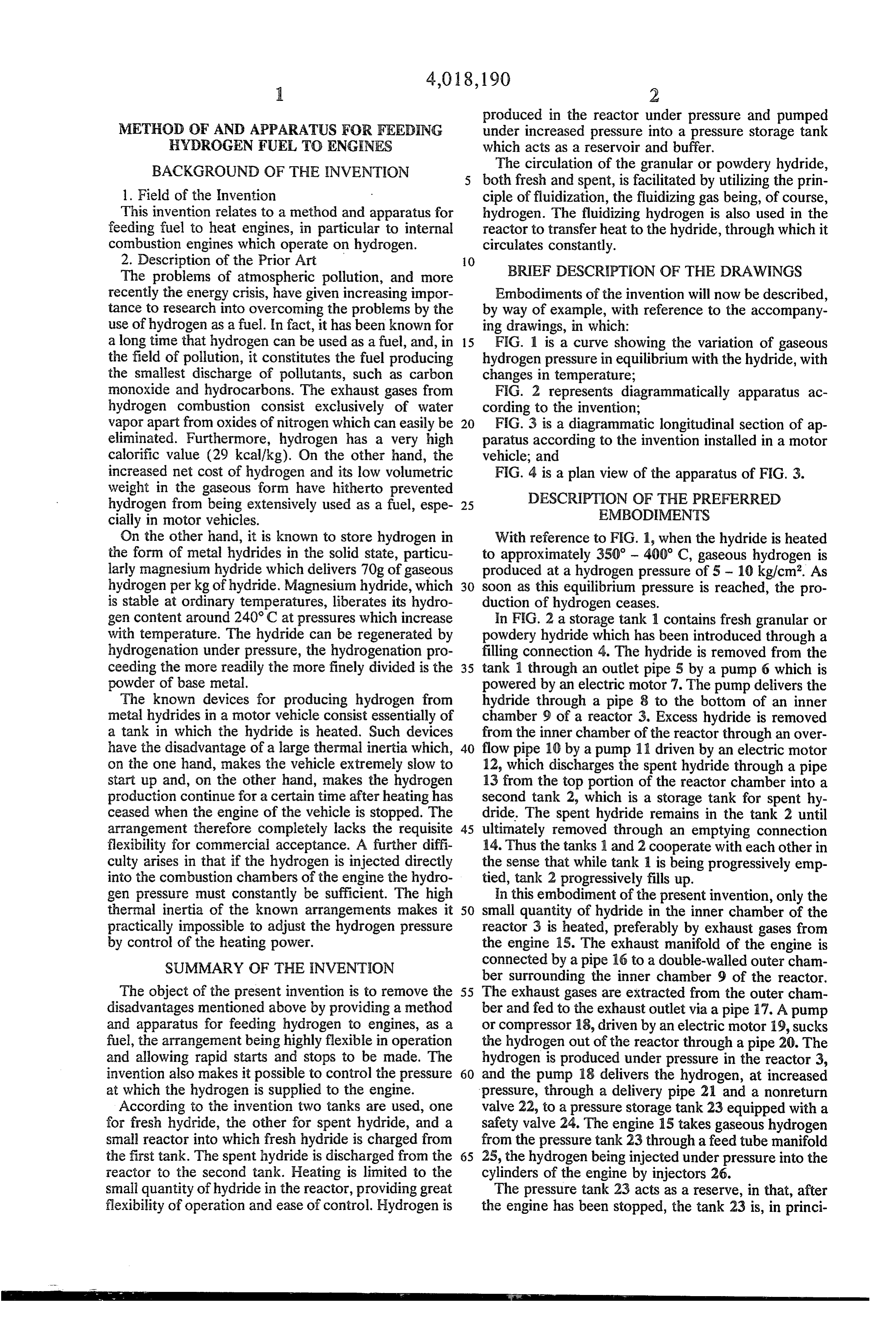
METHOD OF AND APPARATUS FOR FEEDING under increased pressure into a pressure storage tank HYDROGEN FUEL TO ENGINES which acts as a reservoir and buffer. BACKGROUND OF THE INVENTION The circulation of the granular or powdery hydride, both fresh and spent, is facilitated by utilizing the prin 1. Field of the Invention ciple of fluidization, the fluidizing gas being, of course, This invention relates to a method and apparatus for hydrogen. The fluidizing hydrogen is also used in the feeding fuel to heat engines, in particular to internal reactor to transfer heat to the hydride, through which it combustion engines which operate on hydrogen. circulates constantly.
BRIEF DESCRIPTION OF THE DRAWINGS
The problems of atmospheric pollution, and more recently the energy crisis, have given increasing impor Embodiments of the invention will now be described, tance to research into overcoming the problems by the by way of example, with reference to the accompany use of hydrogen as a fuel. In fact, it has been known for ing drawings, in which:
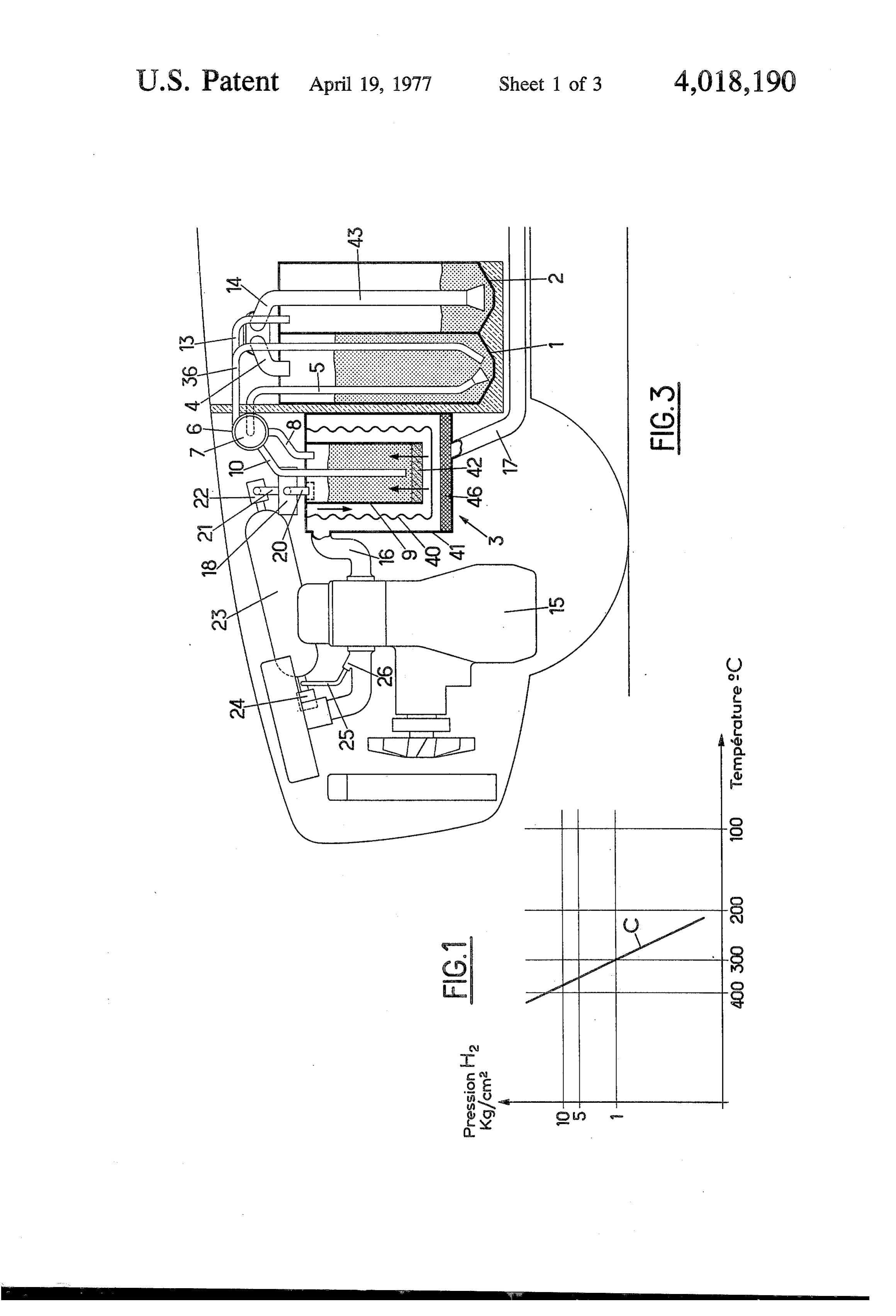
a long time that hydrogen can be used as a fuel, and, in 15 FIG. 1 is a curve showing the variation of gaseous the field of pollution, it constitutes the fuel producing hydrogen pressure in equilibrium with the hydride, with the smallest discharge of pollutants, such as carbon changes in temperature;
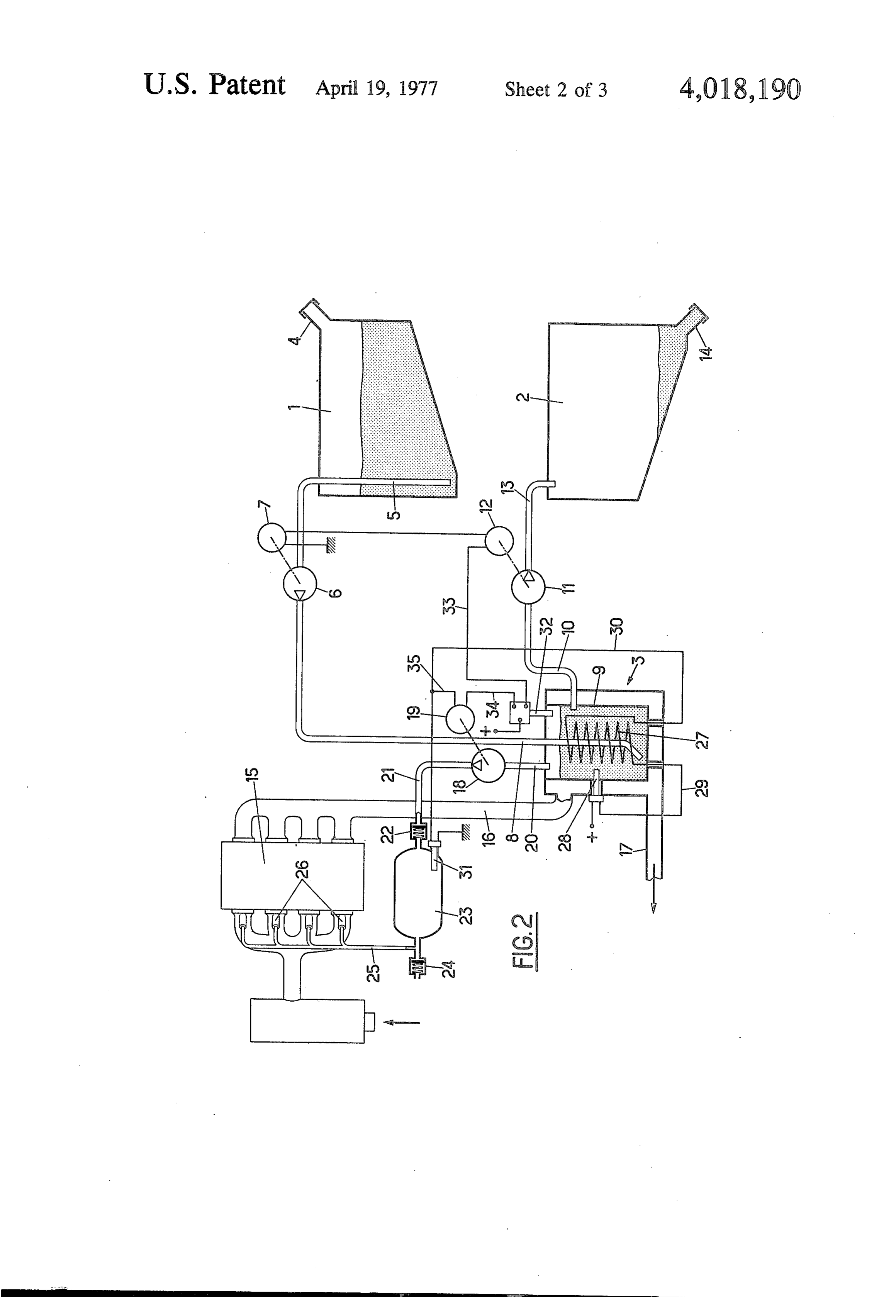
monoxide and hydrocarbons. The exhaust gases from FIG. 2 represents diagrammatically apparatus ac hydrogen combustion consist exclusively of water cording to the invention;
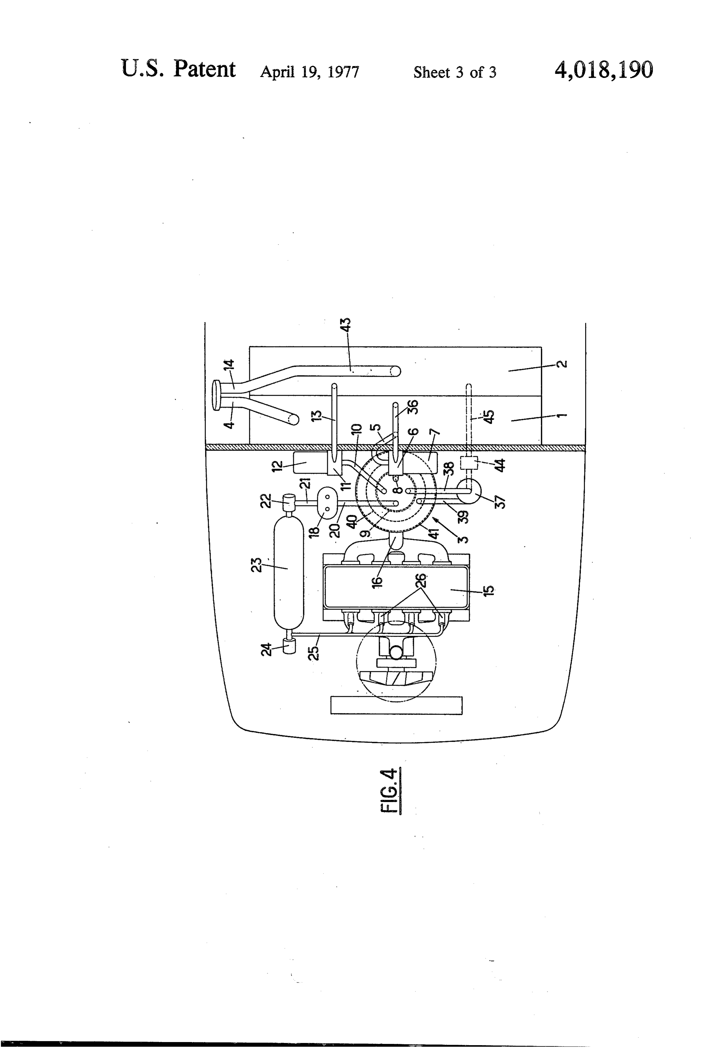
vapor apart from oxides of nitrogen which can easily be 20 FIG. 3 is a diagrammatic longitudinal section of ap eliminated. Furthermore, hydrogen has a very high paratus according to the invention installed in a motor calorific value (29 kcal/kg). On the other hand, the vehicle, and increased net cost of hydrogen and its low volumetric FIG. 4 is a plan view of the apparatus of FIG. 3. weight in the gaseous form have hitherto prevented DESCRIPTION OF THE PREFERRED hydrogen from being extensively used as a fuel, espe EMBODEMENTS cially in motor vehicles.
On the other hand, it is known to store hydrogen in With reference to FIG. 1, when the hydride is heated the form of metal hydrides in the solid state, particu to approximately 350 - 400 C, gaseous hydrogen is larly magnesium hydride which delivers 70g of gaseous produced at a hydrogen pressure of 5 - 10 kg/cm. As hydrogen per kg of hydride. Magnesium hydride, which 30 soon as this equilibrium pressure is reached, the pro is stable at ordinary temperatures, liberates its hydro duction of hydrogen ceases.
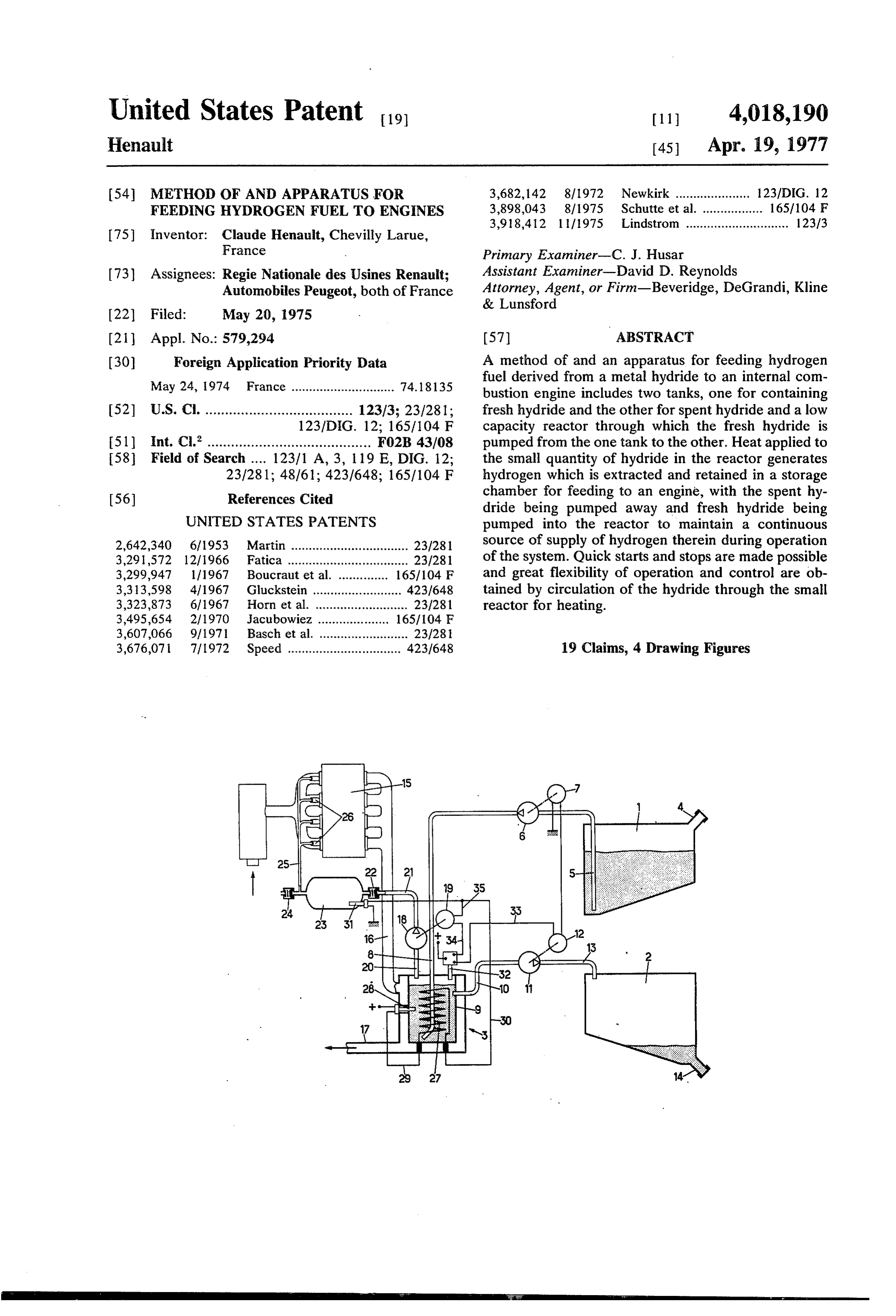
gen content around 240°C at pressures which increase In FIG. 2 a storage tank 1 contains fresh granular or with temperature. The hydride can be regenerated by powdery hydride which has been introduced through a hydrogenation under pressure, the hydrogenation pro filling connection 4. The hydride is removed from the ceeding the more readily the more finely divided is the 35 tank 1 through an outlet pipe 5 by a pump 6 which is powder of base metal. powered by an electric motor 7. The pump delivers the The known devices for producing hydrogen from hydride through a pipe 8 to the bottom of an inner metal hydrides in a motor vehicle consist essentially of chamber 9 of a reactor 3. Excess hydride is removed a tank in which the hydride is heated. Such devices from the inner chamber of the reactor through an over have the disadvantage of a large thermal inertia which, 40 flow pipe 10 by a pump 11 driven by an electric motor on the one hand, makes the vehicle extremely slow to 12, which discharges the spent hydride through a pipe start up and, on the other hand, makes the hydrogen 13 from the top portion of the reactor chamber into a production continue for a certain time after heating has second tank 2, which is a storage tank for spent hy ceased when the engine of the vehicle is stopped. The dride. The spent hydride remains in the tank 2 until arrangement therefore completely lacks the requisite 45 ultimately removed through an emptying connection flexibility for commercial acceptance. A further diffi 14. Thus the tanks 1 and 2 cooperate with each other in culty arises in that if the hydrogen is injected directly the sense that while tank 1 is being progressively emp into the combustion chambers of the engine the hydro tied, tank 2 progressively fills up. gen pressure must constantly be sufficient. The high In this embodiment of the present invention, only the thermal inertia of the known arrangements makes it 50 small quantity of hydride in the inner chamber of the practically impossible to adjust the hydrogen pressure reactor 3 is heated, preferably by exhaust gases from by control of the heating power. the engine 15. The exhaust manifold of the engine is SUMMARY OF THE INVENTION connected by a pipe 16 to a double-walled outer cham ber surrounding the inner chamber 9 of the reactor.
The object of the present invention is to remove the 55 The exhaust gases are extracted from the outer cham disadvantages mentioned above by providing a method ber and fed to the exhaust outlet via a pipe 17. A pump and apparatus for feeding hydrogen to engines, as a or compressor 18, driven by an electric motor 19, sucks fuel, the arrangement being highly flexible in operation the hydrogen out of the reactor through a pipe 20. The and allowing rapid starts and stops to be made. The hydrogen is produced under pressure in the reactor 3, invention also makes it possible to control the pressure 60 and the pump 18 delivers the hydrogen, at increased at which the hydrogen is supplied to the engine. pressure, through a delivery pipe 21 and a nonreturn According to the invention two tanks are used, one valve 22, to a pressure storage tank 23 equipped with a for fresh hydride, the other for spent hydride, and a safety valve 24. The engine 15 takes gaseous hydrogen small reactor into which fresh hydride is charged from from the pressure tank 23 through a feed tube manifold the first tank. The spent hydride is discharged from the 65 25, the hydrogen being injected under pressure into the reactor to the second tank. Heating is limited to the cylinders of the engine by injectors 26. small quantity of hydride in the reactor, providing great The pressure tank 23 acts as a reserve, in that, after flexibility of operation and ease of control. Hydrogen is the engine has been stopped, the tank 23 is, in princi
Page 6
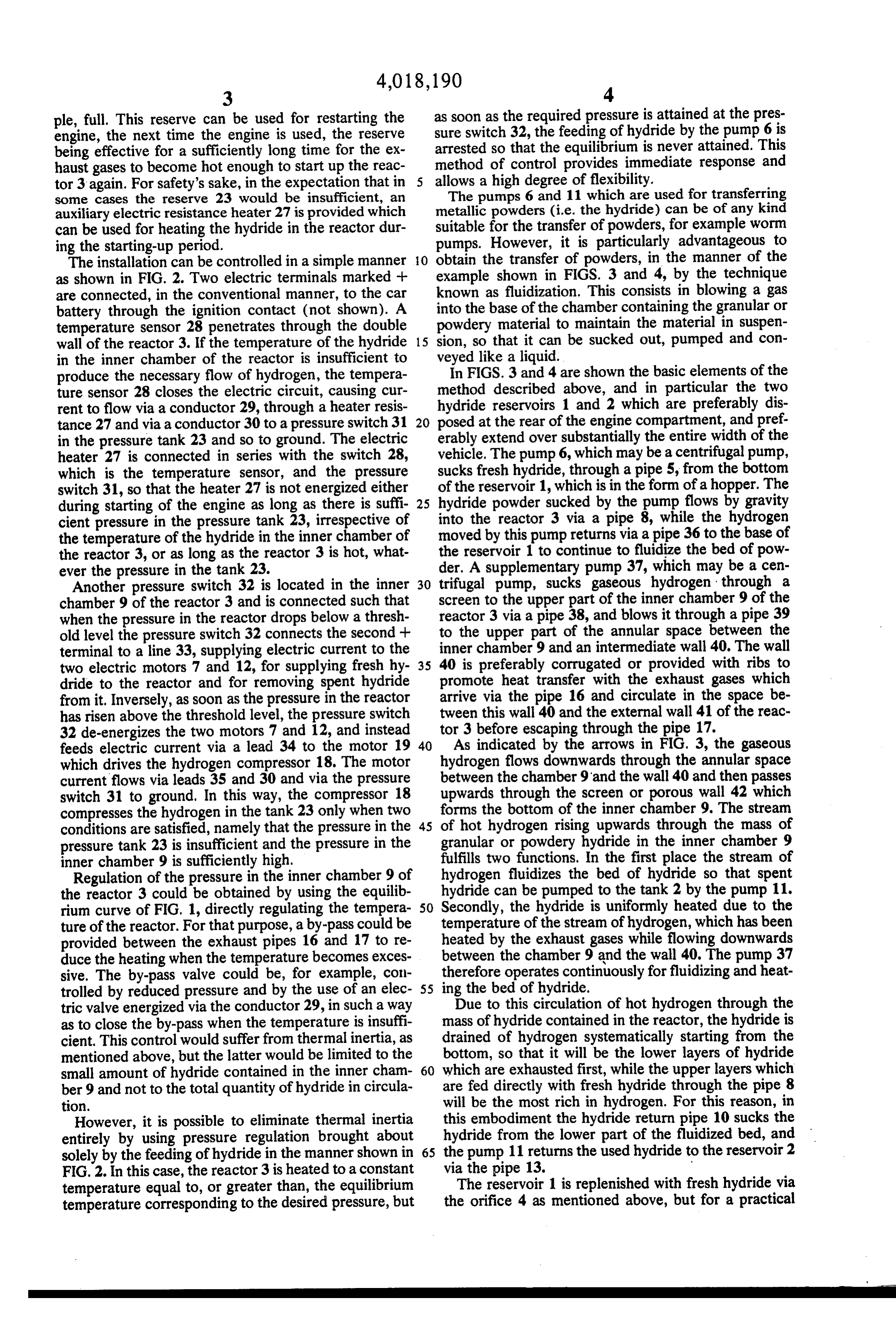
ple, full. This reserve can be used for restarting the as soon as the required pressure is attained at the pres engine, the next time the engine is used, the reserve sure switch 32, the feeding of hydride by the pump 6 is being effective for a sufficiently long time for the ex arrested so that the equilibrium is never attained. This haust gases to become hot enough to start up the reac method of control provides immediate response and tor 3 again. For safety's sake, in the expectation that in allows a high degree of flexibility. some cases the reserve 23 would be insufficient, an The pumps 6 and 11 which are used for transferring auxiliary electric resistance heater 27 is provided which metallic powders (i.e. the hydride) can be of any kind can be used for heating the hydride in the reactor dur suitable for the transfer of powders, for example worm ing the starting-up period. pumps. However, it is particularly advantageous to The installation can be controlled in a simple manner 10 obtain the transfer of powders, in the manner of the as shown in FIG. 2. Two electric terminals marked -- example shown in FIGS. 3 and 4, by the technique are connected, in the conventional manner, to the car known as fluidization. This consists in blowing a gas battery through the ignition contact (not shown). A into the base of the chamber containing the granular or temperature sensor 28 penetrates through the double powdery material to maintain the material in suspen wall of the reactor 3. If the temperature of the hydride 15 sion, so that it can be sucked out, pumped and con in the inner chamber of the reactor is insufficient to veyed like a liquid.
produce the necessary flow of hydrogen, the tempera In FIGS. 3 and 4 are shown the basic elements of the ture sensor 28 closes the electric circuit, causing cur method described above, and in particular the two rent to flow via a conductor 29, through a heater resis hydride reservoirs 1 and 2 which are preferably dis tance 27 and via a conductor 30 to a pressure switch 31 20 posed at the rear of the engine compartment, and pref. in the pressure tank 23 and so to ground. The electric erably extend over substantially the entire width of the heater 27 is connected in series with the switch 28, vehicle. The pump 6, which may be a centrifugal pump, which is the temperature sensor, and the pressure sucks fresh hydride, through a pipe 5, from the bottom switch 31, so that the heater 27 is not energized either of the reservoir 1, which is in the form of a hopper. The during starting of the engine as long as there is suffi 25 hydride powder sucked by the pump flows by gravity cient pressure in the pressure tank 23, irrespective of into the reactor 3 via a pipe 8, while the hydrogen the temperature of the hydride in the inner chamber of moved by this pump returns via a pipe 36 to the base of the reactor 3, or as long as the reactor 3 is hot, what the reservoir 1 to continue to fluidize the bed of pow ever the pressure in the tank 23. der. A supplementary pump 37, which may be a cen Another pressure switch 32 is located in the inner 30 trifugal pump, sucks gaseous hydrogen through a chamber 9 of the reactor 3 and is connected such that screen to the upper part of the inner chamber 9 of the when the pressure in the reactor drops below a thresh reactor 3 via a pipe 38, and blows it through a pipe 39 old level the pressure switch 32 connects the second + to the upper part of the annular space between the terminal to a line 33, supplying electric current to the inner chamber 9 and an intermediate wall 40. The wall two electric motors 7 and 12, for supplying fresh hy 35 40 is preferably corrugated or provided with ribs to dride to the reactor and for removing spent hydride promote heat transfer with the exhaust gases which from it, Inversely, as soon as the pressure in the reactor arrive via the pipe 16 and circulate in the space be has risen above the threshold level, the pressure switch tween this wall 40 and the external wall 41 of the reac 32 de-energizes the two motors 7 and 12, and instead tor 3 before escaping through the pipe 17. feeds electric current via a lead 34 to the motor 19 40 As indicated by the arrows in FIG, 3, the gaseous which drives the hydrogen compressor 18. The motor hydrogen flows downwards through the annular space current flows via leads 35 and 30 and via the pressure between the chamber 9 and the wall 40 and then passes switch 31 to ground. In this way, the compressor 18 forms upwards through the screen or porous wall 42 which compresses the hydrogen in the tank 23 only when two the bottom of the inner chamber 9. The stream conditions are satisfied, namely that the pressure in the 45 of hot hydrogen rising upwards through the mass of pressure tank 23 is insufficient and the pressure in the granular or powdery hydride in the inner chamber 9 inner chamber 9 is sufficiently high. fulfills two functions. In the first place the stream of Regulation of the pressure in the inner chamber 9 of hydrogen fluidizes the bed of hydride so that spent the reactor 3 could be obtained by using the equilib hydride can be pumped to the tank 2 by the pump 11. rium curve of FIG. 1, directly regulating the tempera 50 Secondly, the hydride is uniformly heated due to the ture of the reactor. For that purpose, a by-pass could be temperature of the stream of hydrogen, which has been provided between the exhaust pipes 16 and 17 to re heated by the exhaust gases while flowing downwards duce the heating when the temperature becomes exces between the chamber 9 and the wall 40. The pump 37 sive. The by-pass valve could be, for example, con therefore operates continuously for fluidizing and heat trolled by reduced pressure and by the use of an elec 55 ing the bed of hydride.
tric valve energized via the conductor 29, in such a way Due to this circulation of hot hydrogen through the as to close the by-pass when the temperature is insuffi mass of hydride contained in the reactor, the hydride is cient. This control would suffer from thermal inertia, as drained of hydrogen systematically starting from the mentioned above, but the latter would be limited to the bottom, so that it will be the lower layers of hydride small amount of hydride contained in the inner cham 60 which are exhausted first, while the upper layers which ber 9 and not to the total quantity of hydride in circula are fed directly with fresh hydride through the pipe 8 tion. will be the most rich in hydrogen. For this reason, in However, it is possible to eliminate thermal inertia this embodiment the hydride return pipe 10 sucks the entirely by using pressure regulation brought about hydride from the lower part of the fluidized bed, and solely by the feeding of hydride in the manner shown in 65 the pump 11 returns the used hydride to the reservoir 2 FIG. 2. In this case, the reactor 3 is heated to a constant via the pipe 13.
temperature equal to, or greater than, the equilibrium The reservoir 1 is replenished with fresh hydride via temperature corresponding to the desired pressure, but the orifice 4 as mentioned above, but for a practical
Page 7
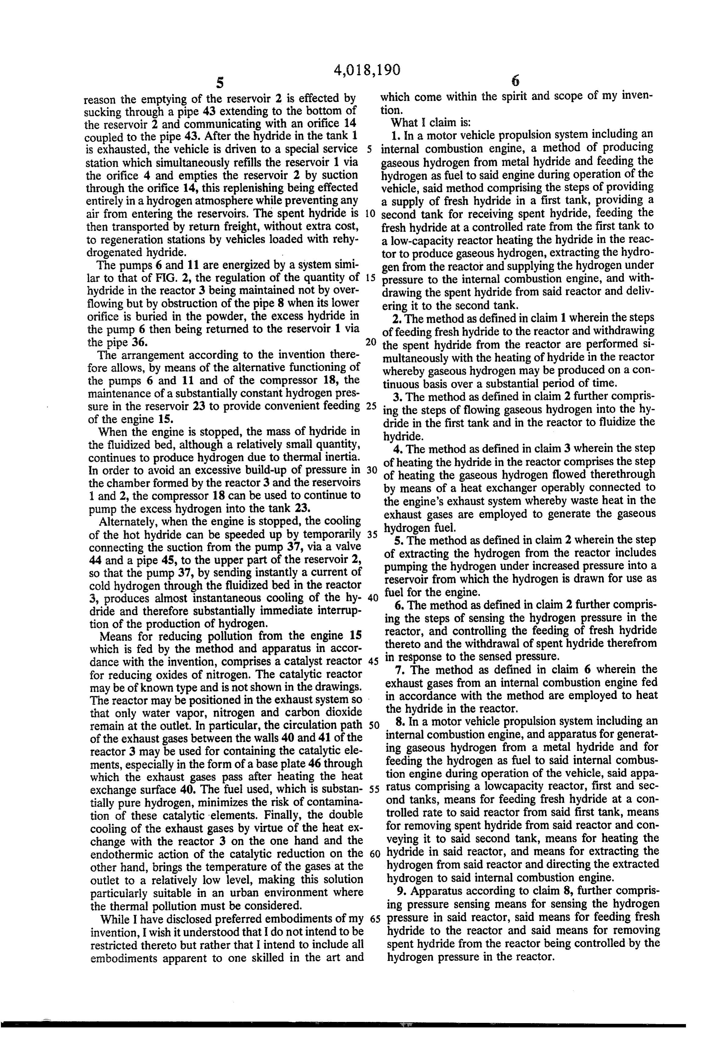
reason the emptying of the reservoir 2 is effected by which come within the spirit and scope of my inven sucking through a pipe 43 extending to the bottom of tion.
the reservoir 2 and communicating with an orifice 14 What I claim is:
coupled to the pipe 43. After the hydride in the tank 1 1. In a motor vehicle propulsion system including an is exhausted, the vehicle is driven to a special service internal combustion engine, a method of producing station which simultaneously refills the reservoir 1 via gaseous hydrogen from metal hydride and feeding the the orifice 4 and empties the reservoir 2 by suction hydrogen as fuel to said engine during operation of the through the orifice 14, this replenishing being effected vehicle, said method comprising the steps of providing entirely in a hydrogen atmosphere while preventing any a supply of fresh hydride in a first tank, providing a air from entering the reservoirs. The spent hydride is 10 second tank for receiving spent hydride, feeding the then transported by return freight, without extra cost, fresh hydride at a controlled rate from the first tank to to regeneration stations by vehicles loaded with rehy a low-capacity reactor heating the hydride in the reac drogenated hydride. tor to produce gaseous hydrogen, extracting the hydro The pumps 6 and 11 are energized by a system simi gen from the reactor and supplying the hydrogen under lar to that of FIG. 2, the regulation of the quantity of 15 pressure to the internal combustion engine, and with hydride in the reactor 3 being maintained not by over drawing the spent hydride from said reactor and deliv flowing but by obstruction of the pipe 8 when its lower ering it to the second tank.
orifice is buried in the powder, the excess hydride in 2. The method as defined in claim 1 wherein the steps the pump 6 then being returned to the reservoir 1 via offeeding fresh hydride to the reactor and withdrawing the pipe 36. 20 the spent hydride from the reactor are performed si The arrangement according to the invention there multaneously with the heating of hydride in the reactor fore allows, by means of the alternative functioning of whereby gaseous hydrogen may be produced on a con the pumps 6 and 11 and of the compressor 18, the maintenance of a substantially constant hydrogen pres tinuous 3. The basis over a substantial period of time.
method as defined in claim 2 further compris sure in the reservoir 23 to provide convenient feeding 25 ing the steps of flowing gaseous hydrogen into the hy of the engine 15. dride in the first tank and in the reactor to fluidize the When the engine is stopped, the mass of hydride in hydride.
the fluidized bed, although a relatively small quantity, continues to produce hydrogen due to thermal inertia. of4.heating The method as defined in claim 3 wherein the step In order to avoid an excessive build-up of pressure in 30 of heating the hydride in the reactor comprises the step the gaseous hydrogen flowed therethrough the chamber formed by the reactor 3 and the reservoirs by means of a heat exchanger operably connected to 1 and 2, the compressor 18 can be used to continue to the engine's exhaust system whereby waste heat in the pump the excess hydrogen into the tank 23.
Alternately, when the engine is stopped, the cooling exhaust hydrogen gases are employed to generate the gaseous fuel.
of the hot hydride can be speeded up by temporarily 35 5. The method connecting the suction from the pump 37, via a valve of extracting theashydrogen defined in claim 2 wherein the step from the reactor includes 44 and a pipe 45, to the upper part of the reservoir 2, so that the pump 37, by sending instantly a current of pumping the hydrogen under increased pressure into a cold hydrogen through the fluidized bed in the reactor reservoir from which the hydrogen is drawn for use as 3, produces almost instantaneous cooling of the hy 40 fuel6. The for the engine.
method as defined in claim 2 further compris dride and therefore substantially immediate interrup ing the steps of sensing the hydrogen pressure in the tion of the production of hydrogen. reactor, and controlling the feeding of fresh hydride Means for reducing pollution from the engine 15 which is fed by the method and apparatus in accor thereto and the withdrawal of spent hydride therefrom dance with the invention, comprises a catalyst reactor 45 in7.response to the sensed pressure. The method as defined in claim 6 wherein the for reducing oxides of nitrogen. The catalytic reactor exhaust gases from an internal combustion engine fed may be of known type and is not shown in the drawings. in accordance with the method are employed to heat The reactor may be positioned in the exhaust system so the hydride in the reactor. that only water vapor, nitrogen and carbon dioxide 8. In a motor vehicle propulsion system including an remain at the outlet. In particular, the circulation path internal combustion engine,
of the exhaust gases between the walls 40 and 41 of the ing gaseous hydrogen from and apparatus for generat a metal hydride and for reactor 3 may be used for containing the catalytic ele ments, especially in the form of a base plate 46through feeding tion the hydrogen as fuel to said internal combus engine during operation of the vehicle, said appa which the exhaust gases pass after heating the heat exchange surface 40. The fuel used, which is substan 55 ond ratus comprising a lowcapacity reactor, first and sec tially pure hydrogen, minimizes the risk of contamina tanks, means for feeding fresh hydride at a con tion of these catalytic elements. Finally, the double trolled rate to said reactor from said first tank, means cooling of the exhaust gases by virtue of the heat ex for removing spent hydride from said reactor and con change with the reactor 3 on the one hand and the veying it to said second tank, means for heating the endothermic action of the catalytic reduction on the 60 hydride in said reactor, and means for extracting the other hand, brings the temperature of the gases at the hydrogen from said reactor and directing the extracted outlet to a relatively low level, making this solution hydrogen to said internal combustion engine. particularly suitable in an urban environment where 9. Apparatus according to claim 8, further compris the thermal pollution must be considered. ing pressure sensing means for sensing the hydrogen While I have disclosed preferred embodiments of my 65 pressure in said reactor, said means for feeding fresh invention, I wish it understood that I do not intend to be hydride to the reactor and said means for removing restricted thereto but rather that I intend to include all spent hydride from the reactor being controlled by the embodiments apparent to one skilled in the art and hydrogen pressure in the reactor.
Page 8
10. Apparatus according to claim 9 wherein said ing gaseous hydrogen from a metal hydride and feeding means for heating the hydride in said low-capacity the hydrogen as fuel to the engine during operation of reactor comprises heat exchange means operably con the vehicle, said apparatus comprising a low-capacity nected to the engine's exhaust system for extracting reactor, first and second tanks, means for feeding fresh heat from the exhaust gases. hydride to said reactor from said first tank, means for 11. Apparatus according to claim 10 further compris removing spent hydride from said reactor and convey ing an auxiliary heater for heating the reactor for start ing it to said second tank, pressure sensing means for ing the reactor up from the cold when the exhaust gases sensing the hydrogen pressure in said reactor, said have not attained a sufficient temperature to heat the means for feeding fresh hydride to said reactor and said reactor. 10 means for removing said spent hydride from said reac 12. Apparatus according to claim 11 wherein said tor being controlled by said pressure sensing means, auxiliary heater comprises an electrical resistance heating means for heating the hydride in said reactor, heater. said heating means including heat exchanger means 13. Apparatus according to claim 8 further compris operably connected to the engine's exhaust system for ing means directing fluidizing currents of hydrogen gas 15 extracting heat from the exhaust gases and means flow into the hydride in said first tank and said reactor, and ing gaseous hydrogen through said heat exchanger centrifugal pump means for pumping fresh hydride means to pick up heat from the engine exhaust gases, from said first tank and spent hydride from said reac means directing said heated hydrogen gas through the to. hydride in said reactor to assist in the fluidization of the 14. Apparatus according to claim 8 further compris 20 hydride, and means for extracting the hydrogen from ing a reservoir, pump means operably connected be said said reactor and directing the extracted hydrogen to internal combustion engine.
tween said reservoir and said reactor for extracting 19. In a motor vehicle propulsion system including an hydrogen produced in the reactor and delivering it at internal combustion increased pressure for storage in said reservoir from ing gaseous hydrogenengine, an apparatus for generat from a metal hydride and for which the hydrogen is extracted for feeding the engine. 25 feeding 15. Apparatus according to claim 14 including means ation ofthe the hydrogen as fuel to the engine during oper vehicle, said apparatus comprising a low directing hydrogen stored in said reservoir to the en capacity reactor, gine for starting the engine prior to starting said reac directing fluidizingfirst and second tanks, means for currents of hydrogen gas into the tor.
hydride in said first tank and in said reactor, centrifical 16. Apparatus according to claim 8 wherein said first 30 pump and second hydride tanks are situated on said vehicle tank means for pumping fresh hydride from said first behind the engine and extend trasversely thereof and and conveyingand for removing spent hydride from said reactor wherein each tank has a bottom in the form of a hop ing the hydrideit inintosaid said second tank, means for heat reactor including a pump for per.
17. Apparatus according to claim 16 including a 35 the reactor, said pump forthrough circulating hot hydrogen the bed of hydride in double connection used for filling and emptying the its inlet pipe connected through a valvehydrogen circulating having hydride, one portion of the connection communicating in one of said tanks whereby upon opening of thespace to the gas valve with the top of the first tank for charging this tank with as when the engine of the vehicle stops, a current of fresh hydride under gravity, with other portion of the cold hydrogen is sent from the one tank through the connection communicating with the bottom of the 40 hydride in the reactor to thereby quickly cool the hy second tank for emptying spent hydride from this tank dride, and means for extracting the hydride from said by suction. w reactor and directing the extracted hydrogen to said 18. In a motor vehicle propulsion system including an internal combustion engine.
internal combustion engine, and apparatus for generat 45 sk k k sk xk
Provenance
- Collection
- Cited prior art
- Original PDF
- patentimages.storage.googleapis.com →
- Filed
- 1975-05-20
- Pages
- 8
- Method
- pdftotext (the PDF's own text layer) + pdftoppm 300dpi page scans
- Source
- Google Patents bibliographic record
- Granted
- 1977-04-19
- Inventors
- Claude Henault; Automobiles Peugeot SA; Regie Nationale des Usines Renault
- Transcribed from
- patentimages.storage.googleapis.com →