patent · US3146821
Method of and apparatus for governing the operation of furnaces
1 September 1964
Page 1
Drawing sheet — no readable text.
Page 2
United States Patent Office Patented Sept. 1, 1964
furnace chamber will diffuse more widely substantially 3,46,821 reducing channeling or local burning.
METHOD OF AN APPARATUS FOR GGVERNING Another object of the invention resides in the develop THE OPERATON OF FURNACES ment of a method of and apparatus for utilizing the Fred H. Wietig, 74.45 S. Chicago Ave., Chicago, i. latent heat of the waste flue gases (gases that have at Fied Aug. 29, 1960, Ser. No. 52,712 least once passed through the heating chamber), to main 9 Caians. (C. 158-1) tain the ignition temperature of the fuel and to reclaim This invention is concerned with a method of and a portion of this heat in the furnace or heating chamber apparatus for governing the operation of furnaces, for by recirculating a substantial amount of waste flue gas. example, heating furnaces, annealing furnaces, soaking IO noted Some of the salient features of the invention are briefly pits and the like. below.
In prior systems, there is provided a burner in which The invention provides a long flame burner surrounded fuel and air are intermixed to produce at the burner port by a short flame burner, both burners being disposed a flame which is directed into the furnace chamber. The in a burner combustion chamber opening into a flame combustion temperature thus depends solely upon the 5 duct having a port which terminates in the furnace chamber. Waste gases leave the furnace chamber mixture of fuel and air, producing a relatively very hot through an exhaust conduit leading to a suitable dis flame and correspondingly hot gases in the furnace cham charge, for example, a chimney, such exhaust conduit ber, such gases acting moreover in the nature of oxidizing being provided with a bypass connected with one branch gases. This is in many cases undesirable, for example, in the heating of materials, particularly steel, to a tem 20 of duct, an air supply conduit and terminating in the flame for supplying thereto hot waste gases and air for in perature below the melting point, because the very hot termixture with the fuel injected thereinto by the long flame and the hot oxidizing gases tend to "burn' the steel flame burner, another branch of the air supply conduit furnace. In systems where the burner discharges di terminating in the burner combustion chamber for Sup rectly into the heating chamber, most of the combustion plying air thereto for intermixture with fuel injected will take place in the heating chamber, tending to cause 25 channeling and localized burning which will prevent uni by the short flame burner.
form heating. Valve means are disposed in fuel supply conduits There are also systems which preheat the air by means which interconnect the two burners and damper or valve of a recuperator or regenerator in order to recover the means are respectively disposed in the branches of the air latent heat from the waste gas, but the use of preheated 30 are supply conduit, and said valve means and damper means air with raw fuel also raises the combustion temperature operatively controlled by common link means de and is often objectionable and there have been attempts pending upon the temperature obtaining in the waste gas to control this temperature by introducing inert or low bypass, whereby fuel and air supply to the short flame heat content gases into the fuel system. burner can be automatically reduced (or increased) while 35 simultaneously increasing (or reducing) the fuel Supply
Systems for mixing low heat content gases or inert gases to the long flame burner and coincidentally with air or raw fuel without means for maintaining the also increas ignition temperature of a mixture of fuel and air can ing (or reducing) the air supply to the waste gas bypass. cause the flame to go out and create a dangerous explo If desired, heat recuperator means may be provided sion hazard in the furnace or heating chamber. Nu in known manner in the exhaust conduit for utilizing merous such explosions have occurred with disasterous 40 waste with gases coming from the furnace chamber, together valve control means, for selectively preheating the results. air supplied to the two branches of the air supply conduit. Systems in which temperature sensing devices are Damper means are disposed in the waste gas bypass placed in the heating chamber for detecting gas tempera and operatively controlled by the action of temperature tures cannot determine waste gas temperatures because heat is being lost from the hot gases to the material being 45 sensing pass and means disposed respectively at a point in the by at a point in the exhaust conduit, further damper heated so that the varying gas temperatures obtained means being provided in the exhaust conduit and opera will depend upon the distance from the burner, the rate at tively controlled by control means responsive to the pres which heat is being lost to the material being heated and sure obtaining in the furnace chamber in known manner. to the heating chamber walls, and through cracks around The drawing illustrates in semi-diagrammatic form a the doors, covers, and other openings. Waste gas tem 50 perature sensing devices placed in the waste gas duct a heating system embodying the invention. reasonable distance from the heating chamber will give a The foregoing and other objects and features of the uniform accurate indication of the temperature of the invention will appear from the description of an embodi Waste gas, since the waste gas duct contains no material ment thereof which is rendered below with reference to to be heated and may be constructed of insulating mate 55 theReferring accompanying drawing.
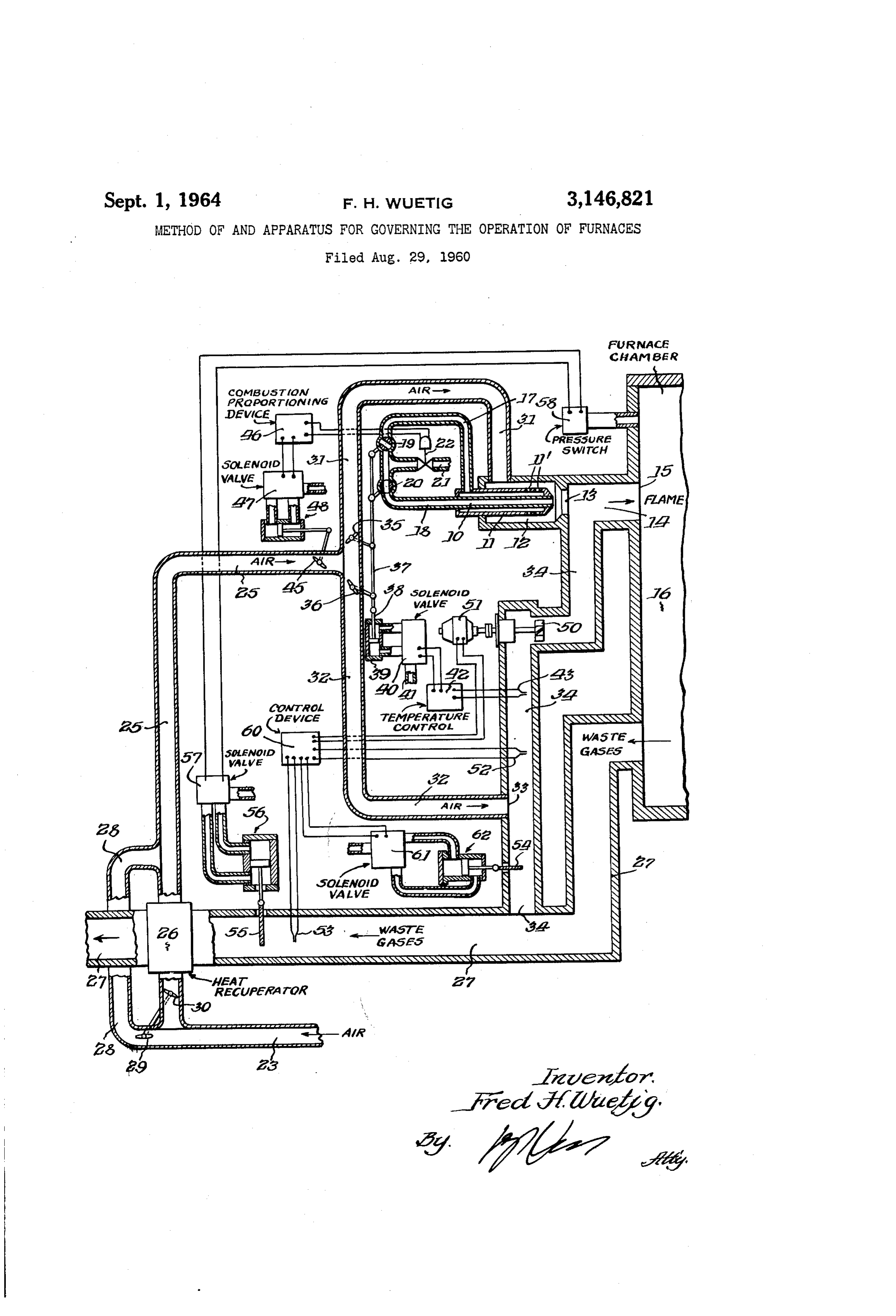
now to the drawing, numeral 6 indicates the rials and is tightly sealed, reducing heat losses to a long flame burner surrounded by the short flame burner minimum. ii, the latter having outlets i' formed therein, such The principal object of the invention is to eliminate burners forming a unit which is disposed within the the above noted drawbacks or at least to improve oper burner combustion chamber 2 the orifice 3 of which ating conditions by mixing with the fuel-air combustion opens60 into the flame duct 14, the latter joining a port 15 mixture already burned flue gases (waste gases) coming terminating in the furnace chamber 16. The two burn from the furnace chamber, at a temperature above the ers are interconnected by conduits 17 and 18 containing re ignition temperaturre of fuel and air, thereby increasing spectively valves 19 and 20 for controlling the feed of fuel the gas volume at the burner port and rendering the com bustion mixture practically nonoxidizing. The resulting 65 volume which thereto is supplied to a conduit 21 containing a control solenoid valve 22. Air is supplied to the combustion mixture will moreover burn at a lower tem perature than the mixture of air and fuel alone and the conduit 23 to flow to the duct 25 either through the total available heat in the mixture containing the hot recuperator 26 in which it is heated by waste gases com waste gases will be greater than the heat available in the ing from the furnace chamber 16 and flowing through mixture consisting of air and fuel alone, which is due to 70 flow the exhaust conduit 27, for example, to a chimney, or to the addition of the latent heat of the waste gas. The directly to the duct 25 over the arm 28, the flow of larger volume of combustion gas moving through the air to the duct 25 being selectively controlled by valves
Page 3
29 and 30. The duct 25 has a branch 3 which termi from the air supply branch conduit 32 through the by nates in the burner combustion chamber 12 and a branch pass 34 to the flame duct. 24. While this biower is de 32 which terminates at 33 in the bypass conduit or duct signed to operate at temperatures considerably above the 34, the latter terminating in the flame duct 4 adjacent ignition point of the mixture of fuel and air, the invention the orifice 3 of the burner combustion chambor 2. provides, as a precaution, means for controlling the circu Preheated or cold air can thus be selectively supplied lation of waste gases to prevent passage of gases at tem from the conduit 23 over the branch 31 to the burner com peratures above safe operating temperature of the blower, bustion chamber 2 for intermixture with fuel injected which might damage the blower 39. thereinto through the outlets i' so as to produce a short The invention provides for this purpose a temperature flame, and over the branch 32 and part of the bypass O sensing thermocouple 52 which is disposed in the bypass conduit 34 to the flame duct i4 for intermixture with duct 34 and a damper 54, likewise disposed in the bypass fuel injected into such duct by the burner 6 so as to pro duct. 34. The actuation of the damper 55 is controlled duce the long flame.
Dampers or valves 35 and 36 are respectively disposed abysolenoid a hydraulic system 55 which is in turn governed by valve 57 under control of a pressure switch in the air conduit branches 31 and 32 for controlling the 58 connected with the furnace chamber 6 so as to main supply of air respectively to the burner combustion cham tain substantially uniform positive pressure in the furnace ber 12 (for the short flame burner) and to the flame duct chamber (heating chamber, annealing chamber or soaking 14 (for the long flame burner). pit). It will be noted that the thermocouple 52 is dis The fuel supply valves 9 and 20 and the air supply posed at a point in the bypass 34 above the air Supply valves 35 and 36 are linked to a common operating rod 20 inlet 33 and the temperature of the recirculated waste 37, the actuation of the latter being controlled by a piston gases will thus be lowered by admixture with air. rod 38 connected with a piston contained in cylinder 39. When the thermocouple 52 senses a temperature of the The movement of the piston is controlled by a solenoid gases, flowing through the bypass 34, which is above the valve 40 connected to a fluid pressure line 4. The sole safe operating temperature of the high temperature blow noid valve 40 is controlled by the temperature control 25 er, signals will be given off to the control device 69 to device 42 in accordance with the temperature in the by cause actuation of the solenoid valve 62 which in turn pass 34 which is sensed by a thermocouple 43. The governs the hydraulic system 62 to operate the damper valves 19, 20 in the fuel supply lines 7 and 18 and the 54. So as to stop the flow of the recirculated waste gases, valves 35, 36 in the air supply branches 31, 32, are thus, by the actuation of the control means 37-43 in accordance 30 thereby preventing damage to the blower 59. The ther with the temperature of the gases flowing in the bypass mocouple mocouple 53.
52 thereby acts as an overcontrol on the ther 34, controlled so that when the valves 20 and 36 open, The operation is as follows: fuel will be supplied to the long flame burner 10 and air The operation is initiated by actuating switches (not will at the same time be supplied to the flame duct E4 shown) for placing the various control devices such as while the valves 19 and 35 are simultaneously closed to 35 46-47, 40-42, 60-61 and 57 on current. Combustion shut off fuel and air supply to the short flame burner 11. air is Supplied to the main air inlet conduit 23 by means Conversely, and depending upon the temperature of the of a suitable blower (not shown) and fuel is in suitable gases in the bypass 34, sensed by the thermocouple 43, manner supplied to the fuel supply line 21. The com valves 20 and 36 will be closed to shut off air and fuel bustion proportioning device 46 will actuate the fuel vol supply to the long flame burner 10 while valves 9 and 35 are simultaneously opened to supply fuel and air to 40 ume control valve 22 to maintain fuel volume propor tional to air volume and by means of the solenoid valve the short flame burner 1.
The interplay continues throughout the operation of the 47 and the hydraulic system 43 also the air valve 45 in the apparatus, thus increasing (or reducing) the supply of airmain and air supply conduit 25, thus initiating the supply fuel to the burners. The total volume of air of fuel and air to one burner and at the same time re 45 and fuel together or firing rate may be increased or de ducing (or increasing) the supply of the fuel and air to the creased as desired while maintaining a constant fuel to other burner, thereby providing efficient burner control air proportion. Assuming that the system is started depending upon the temperature of the gases in the bypass cold, the thermocouple 43 will be cold, and the tempera 34, such gases containing air, cold or preheated, supplied ture control 42 will in this condition effect actuation of through the air branch conduit 32 and hot waste gases the Solenoid valve 40 to move the common control rod 37 coming from the furnace chamber 6, exhaust conduit So as to open the fuel valve 19 to supply fuel to the short 27 and the bypass 34. The volume of the gas mixture flame burner 11, such fuel being injected through the in the flame duct 14 is in this manner increased and the outlets 1' into the burner combustion chamber 12, and combustion gases entering the furnace chamber 16 are to open the air valve 35 to supply air through the branch rendered practically nonoxidizing by the admixture of conduit 31 to the burner combustion chamber for inter the waste gases. mixture with the fuel injected by the burner . . The As has been explained before, the volume of fuel Sup fuel valve 20 for the long flame burner 10 will at the plied to the burners is governed by the action of a sole same time be closed and the air valve 36 in the branch noid volume control valve 22 and this volume may be conduit 32 will also be closed. The combustion mixture increased or decreased either manually or automatically 60 in the burner combustion chamber will now be ignited, in response to a suitable controller. The volume of air the short flame burner 11 being in operation, and the Supplied to the respective air conduit branches 31 and 32 burning gases resulting from the intermixture of air and and, therefore, to the burners i0 and 11, for intermixture fuel Will pass through and preheat the flame duct 14 and with the fuel, is similarly governed by an air volume con through port i5 into the furnace chamber 16. The trol valve 45 disposed in the main air supply conduit 25 damper 55 disposed in the waste gas exhaust conduit 27 which will automatically increase or decrease the air vol 65 is initially closed to substantially prevent discharge of ex ume as the fuel volume increases or decreases thereby haust gases. When the pressure in the furnace chamber maintaining a constant fuel to air proportion. Both 16 builds up Sufficiently to prevent infiltration of outside valves 22 and 45 are controlled by a combustion propor air, the pressure switch 58 will be actuated to operate the tioning device 46, the control of the air volume valve 45 Solenoid valve 57, the latter actuating the hydraulic sys being effected by a solenoid valve 47 which is regulated 70 tem 56 to withdraw the damper 55 so as to allow waste by the proportioning device 46 and governs the hydraulic gases to escape, for example, to a chimney (not shown). System 48 linked to the valve 45 as shown. When the waste gases reach a temperature above the A blower 59 which is operated by a motor 51 is pro ignition temperature of the mixture of fuel, and air, the vided for recirculating waste gases intermixed with air thermocouple 53 will produce a signal for causing the control device 60 to actuate the solenoid valve 61, thus
Page 4
operatively effecting the hydraulic system 62 to withdraw chamber and said furnace chamber, burner means ad the damper 54 and to start the motor 51 for actuating the jacent said burner combustion chamber for producing a recirculation blower 50. Waste gases from the exhaust flame directed through said burner combustion chamber conduit 27 are now drawn through the bypass 34 to the and said flame duct into said furnace chamber, and ex flame duct 14 for intermixture with the combustion gases 5 haust conduit means for discharging waste gases from Said from the short flame burner 11. When the temperature furnace chamber, duct means for supplying air to said in the bypass 34 reaches a point slightly below the safe burner means, duct means for returning waste gases ex operating temperature of the high temperature blower 50, hausted from said furnace chamber to adjacent said flame which temperature is considerably above the ignition tem duct for intermixture with fuel and air, said flame duct perature of the fuel and air mixture, the thermocouple 10 being of a substantial length to effect complete combus 43 will deliver a corresponding signal to the temperature tion of the said intermixture of waste gases, air and fuel control 42 and the latter will effect actuation of the sole leaving the flame duct, means disposed in said waste noid valve 40 so as to cause operation of the hydraulic gas return duct for varying the volume of waste gases system 39-38 to move the common control rod 37 for returned, and means responsive to the temperature of the the purpose of operating the fuel valve 9 to reduce fuel 5 waste gases disposed in said return duct remote from said supply to the short flame burner 11 while operating the furnace chamber for controlling said volume varying fuel valve 20 to provide fuel supply to the long flame means to provide an increased volume of hot combusted burner 10, at the same time actuating the valve 35 in the gases when the temperature of the waste gas rises above air supply branch 31 to reduce air supply to the burner the ignition temperature of a mixture of fuel and air combustion chamber and opening the valve 36 in the air 20 alone supplied by said burner to produce a flame with a supply branch 32 to supply air to the bypass 34 to flow larger volume and a temperature lower than a flame pro with the recirculating waste gases to the flame duct 14. duced by a mixture of air and fuel alone. The relatively cool combustion air entering the bypass 2. Apparatus according to claim 1, comprising con 34 effects cooling of the recirculated waste gases. The trol means for initially effecting operation of said burner long flame burner 10 is now operative, injecting fuel into 25 means with air and fuel alone, said burner means dis the flame duct 14 where it is intermixed with the air charging into the flame duct to preheat it before entering waste gas mixture at a temperature above the ignition the furnace chamber, means for coincidently impeding temperature of fuel and air. Combustion of the mix the discharge of waste gases from said furnace chamber ture of raw fuel and the mixture of air and waste gases to build up pressure therein to a point at which infil will take place in the flame duct 14 and at the port 15 30 tration thereinto of outside air is prevented and means opening into the furnace chamber 6. The heat released for thereupon effecting the discharge of said waste gases. by the combustion is added to the latent heat in the re 3. In an apparatus for heat treating materials dis circulated waste gases, giving a larger gas volume with posed in a furnace chamber the combination of a struc a greater heat content than could be obtained by burning ture having walls forming such a furnace chamber, a fuel and air alone. Conversely the cycle of operation is flame duct terminating in a port formed in a wall of said reversed if the temperature in the waste gas bypass falls furnace chamber and an exhaust conduit for withdrawing until it reaches the ignition temperature of a mixture of from said furnace chamber waste gases, means forming fuel and air whereupon the damper 54 closes stopping the a burner combustion chamber operatively connected by recirculation of waste gas to flame duct 14. said flame duct to the furnace chamber, a first burner The control of the recirculation of waste gases by 40 and second burner disposed in said burner combustion means of the thermocouples 52 and 53 and actuating chamber, means for controlling the supply of air and means respectively associated therewith, has been ex fuel to the first of said burners, to regulate an initial plained before. flame in said burner combustion chamber which is di Hydraulic systems have been shown for actuating the rected into said flame duct and then into said furnace various valves and dampers. It will be understood, 45 chamber, means in said exhaust conduit for sensing the however, that this has been done for convenience of temperature of said waste gases, a bypass duct extending illustration and not for indicating any inherent limita from said exhaust conduit and terminating in said flame tions. Other known systems may be employed for the duct, blower means controllable by said means in said ex purpose in view, for example, electromechanical devices haust conduit, and said blower means being constructed including motor operated drums for winding and unwind 50 to operate at temperature substantially above the ignition ing cables, or motor operated screws with limit switches, temperature of a mixture of fuel and air supplied to said or crank arms cooperatively associated with links, as well burners, and disposed in said bypass duct for diverting a as other known devices for producing nonrotational linear portion of said hot waste gases from said exhaust con motions. Devices such as the pressure switch 58, the duit upon the ascertaining by said means in said exhaust combustion proportioning device 46, solenoid valves 47, 55 conduit of a temperature of said hot waste gases which 40, 57 and 62, as well as the control devices such as 42 exceeds the ignition temperature of fuel and air alone and 60 and the heat recuperator 26, are well known and supplied by said burners, and means governed by said readily available to those experienced in the art, and such controlling means for thereafter mixing air with said devices have therefore been shown diagrammatically as diverted portion of said waste gases and for Supplying blocks to keep the drawing simple. The preheating of 60 fuel to said second burner while reducing the supply of the combustion air by means of a recuperator consti fuel and air to said first burner, said blower means draw tutes an efficient utilization of waste heat but could obvi ing the mixture of air and waste gases into said flame ously be effected differently if desired. It may also be duct for intermixture with the fuel supplied to said second mentioned in conclusion that the various valves and damp burner to produce in said flame duct a relatively long ers may be operated differently even manually if de 65 flame which replaces said initial flame burning in the sired. combustion chamber, the volume of combustion mixture Changes and modifications may be made within the being thereby increased by the addition of said portion Scope and spirit of the appended claims which define of waste gases, such combustion gas mixture burning at what is believed to be new and desired to have protected a temperature below the flame temperature of the mix by Letters Patent. 70 ture of air and fuel alone and producing a correspond I claim: ing substantially increased volume of substantially non 1. An apparatus for improving the operation of a oxidizing combustion gases.
furnace for heat treating materials disposed therein, com 4. Apparatus according to claim 3, comprising means prising means defining a furnace chamber, a burner com for continuously checking the temperature of the mix bustion chamber, a flame duct connecting said burner 75 ture of air and waste gases supplied to said flame duct,
Page 5
and means responsive to said checking means for reduc also including control means governed by said further ing the Supply of waste gases flowing to the flame duct temperature sensing element for controlling the opera responsive to ascertaining an increase of the temperature tion of said damper to cause the cpening of the damper of the mixture which exceeds a point of safe operation when the temperature of the waste gas reaches the igni of Said blower means, said continuous checking means tion temperature of a mixture of fuel and air alone sup acting as an overcontrol of all other means for increasing plied to said burners, and closing said damper when the the flow of waste gas to the flame duct. temperature of waste gas in the bypass falls below the 5. Apparatus according to claim 4, comprising fuel ignition temperature of a mixture of fuel and air alone conduits for respectively supplying fuel to said burners, Supplied to said burners.
a main air supply conduit having two branches going O9. Apparatus according to claim 5, comprising a motor respectively to said burner combustion chamber and to for actuating said blower, said continuously checking said bypass duct, said controlling means including valve means including a further temperature sensing element means in the respective fuel supply conduits and valve disposed in said bypass duct cooperable with said tem means in the respective air supply branches, a common perature sensing means in said exhaust duct, said waste operating member for all of said valve means, means for gas reducing means comprising a damper in said bypass actuating said common operating member, and a tem duct for controlling the passage of waste gases thereinto, perature sensing element in said bypass duct for govern and said continuously checking means also including con ing said last named means to increase the air flow to trol means governed by said further temperature sensing said bypass duct when the waste gas temperature rises element for controlling the operation of said motor and above the ignition temperature of a mixture of fuel 20 of said damper to cause Said motor and blower to stop and air alone supplied by said burners. and said damper to close when the temperature of the 6. Apparatus according to claim 5, comprising a waste gas in the bypass approaches the safe operating further valve in said main air supply conduit controlling temperature of said blower.
the total air Supply, control valve means for controlling the total supply of fuel to said burners, and combustion References Cited in the file of this patent proportioning means for governing the actuation of said UNITED STATES PATENTS further air valve and of said fuel control valve.
7. Apparatus according to claim 4, comprising means 1,332,684 Renner ---------------- Mar. 2, 1920 for preheating the combustion air, and means for selec 1,609,150 Breese ---------------- Nov. 30, 1926 ?tively supplying preheated and Substantially cold air to 1,896,910 Merkt ----------------- Feb. 7, 1933 said burners to continue to maintain temperatures in said 1,926,714 Culbertson ------------- Sept. 12, 1933 waste gas bypass above the ignition temperature of a 2,056,531 Morton ----------------Oct. 6, 1936 mixture of air and fuel alone supplied by said burners 2,214,452 Cox ------------------ Sept. 10, 1940 and below the safe operating temperature of the blower. 2,258,515 Mowat ----------------- Oct. 7, 1941 8. Apparatus according to claim 5, said continuously 2,458,624 Morton et al. ---------- Jan. 11, 1949 checking means comprising a further temperature sens 2,639,910 Cone et al. ------------- May 26, 1953 ing element disposed in said bypass duct cooperable with 2,688,360 Haynes et al. ----------- Sept. 7, 1954 said temperature sensing means in said exhaust conduit, 2,776,827 Graham ----------------- Jan. 8, 1957 said waste gas reducing means comprising a damper in 40 2,991,832 Dailey ---------------- July 11, 1961 said bypass duct for controlling the passage of waste FOREIGN PATENTS gases thereinto, and said continuously checking means 1,119,245 France ----------------- Apr. 3, 1956
Provenance
- Collection
- Cited prior art
- Original PDF
- patentimages.storage.googleapis.com →
- Filed
- 1960-08-29
- Pages
- 5
- Method
- pdftotext (the PDF's own text layer) + pdftoppm 300dpi page scans
- Source
- Google Patents bibliographic record
- Granted
- 1964-09-01
- Inventors
- Fred H Wuetig
- Transcribed from
- patentimages.storage.googleapis.com →