patent · US20070062503A1
Vapor fueled engine
22 March 2007
Page 1 — bibliographic record
(19) United States (12) Patent Application Publication (10) Pub. No.: US 2007/0062503 A1
Bushnell et al. (43) Pub. Date: Mar. 22, 2007 (54) VAPORFUELED ENGINE Related U.S. Application Data (76) Inventors: Raymond Bryce Bushnell, (63) Continuation of application No. 10/706,507, filed on Beavercreek, OR (US); Danny Robert Nov. 11, 2003, now Pat. No. 6,907,866.
Lewis, Beavercreek, OR (US); Robert
William Parry, Oregon City, OR (US) Publication Classification
Correspondence Address: (51) Int. Cl.
SCHWABE, WILLIAMSON & WYATT, P.C. F02D 4/4 (2006.01) PACWEST CENTER, SUITE 1900 F02G 5/00 (2006.01) 1211 SW FIFTHAVENUE (52) U.S. Cl. ............................................ 123/672; 123/546
PORTLAND, OR 97204 (US)
(21) Appl. No.: 10/578,693 A fuel supply assembly is provided that may allow for use (22) PCT Filed: May 7, 2004 of vaporized fuel to power an engine and enhance fuel efficiency. The fuel Supply assembly may include a vapor (86). PCT No.: PCT/USO4f14.146 izing tank, a heating source, a temperature control and a monitoring and control system configured to control inter
S 371(c)(1), mixing of ambient air and vaporized gasoline to maintain a (2), (4) Date: May 9, 2006 desired hydrocarbon level in an exhaust.
Page 2
Drawing sheet — no readable text.
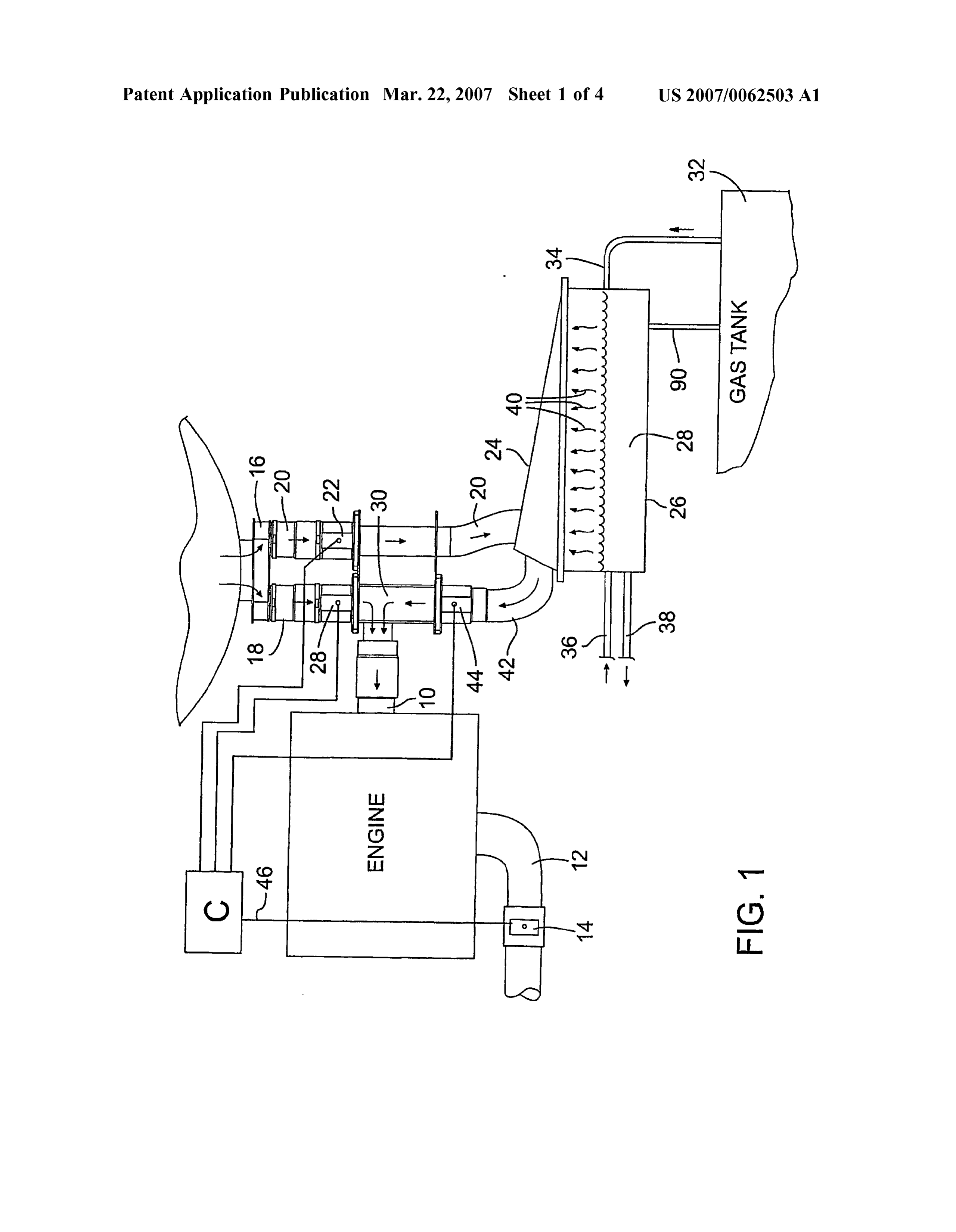
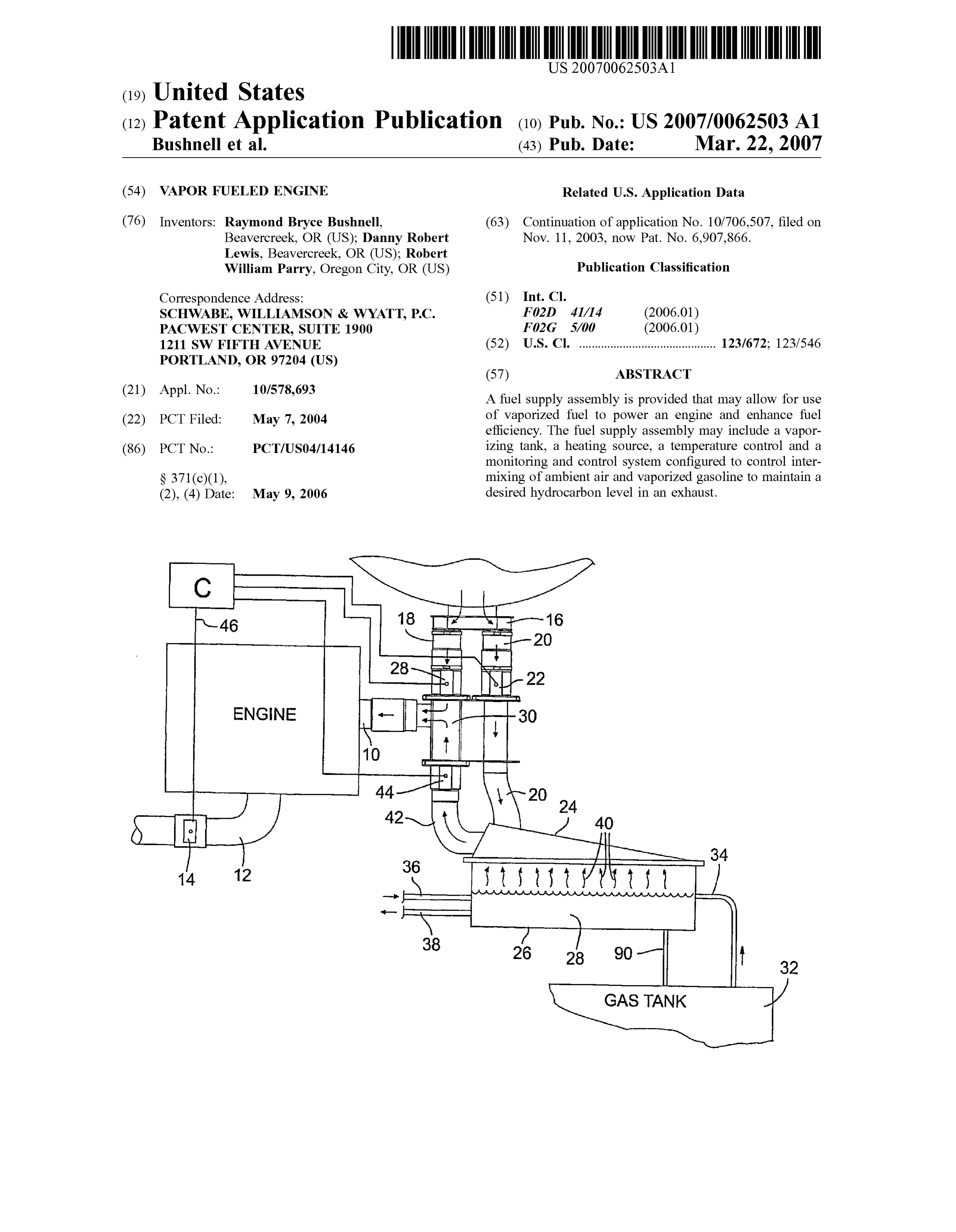
Page 3
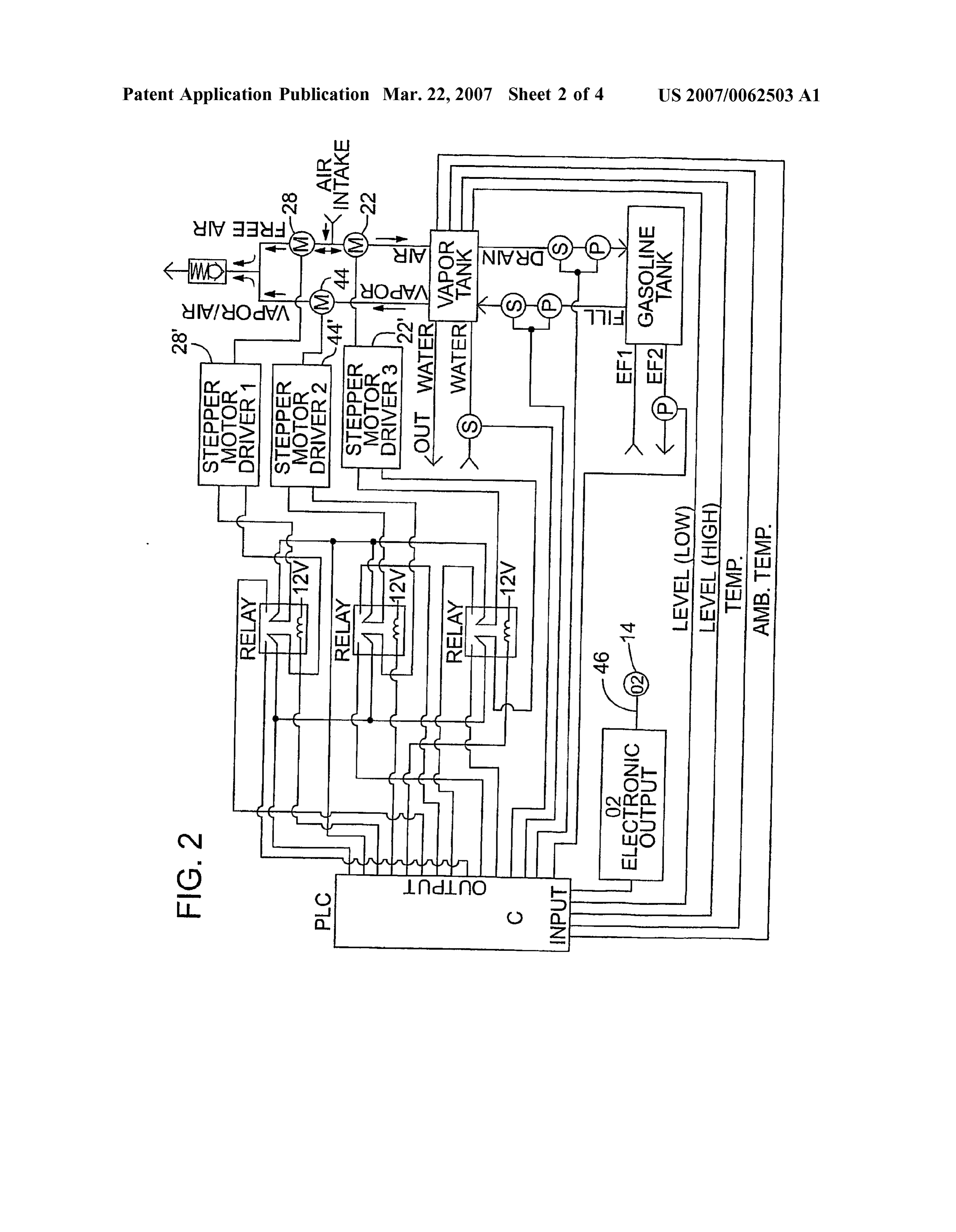
Drawing sheet — no readable text.
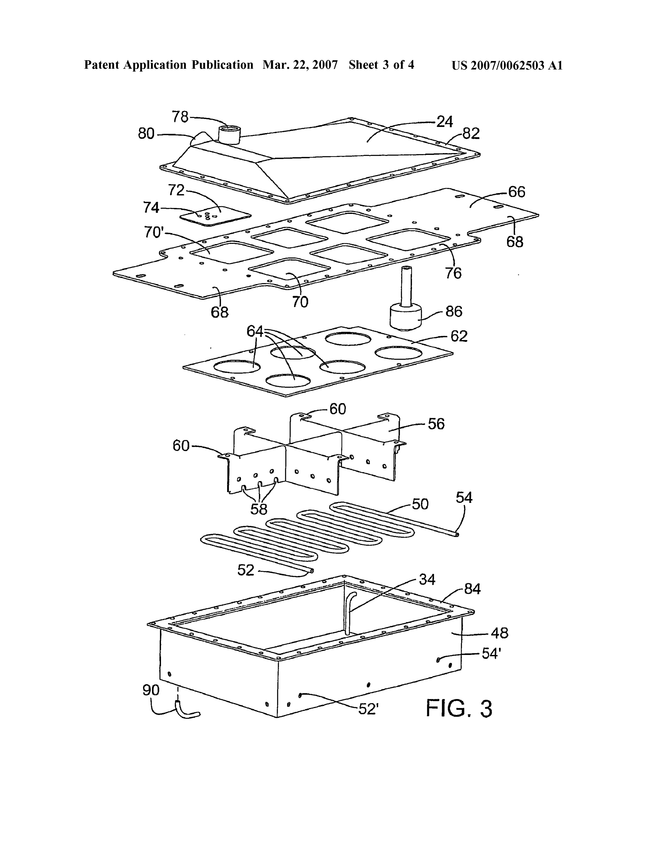
Page 4
Drawing sheet — no readable text.
Page 5
Drawing sheet — no readable text.
Page 6
US 2007/0062503 A1 Mar. 22, 2007
VAPORFUELED ENGINE a 3.2 reading will produce an opening of the ambient air valve and/or a closing of the vaporized fuel flow. A 2.8
FIELD OF THE INVENTION reading will produce the reverse.
0001. This invention relates to the use of vaporized fuel 0008. Whereas it would be presumed and has been to power an engine and, more particularly, to improvements assumed that an established fixed setting of fuel-to-air that enhance fuel efficiency. mixture would produce a stabilized mixture throughout the operation of the engine, Such has been determined to be not
BACKGROUND OF INVENTION the case. There are many variables that need to be controlled 0002. It is known that under some conditions the use of or accommodated. The liquid fuel temperature is known to vaporized fuel versus liquid fuel for gasoline powered have the greatest impact on hydrocarbon emissions and fuel vehicles can reduce the emission of hydrocarbons conveyed efficiency, and that temperature will vary by small but very into the atmosphere, while also increasing fuel efficiency. significant degrees of temperature due to environmental The problem that has lingered is how to obtain and retain changes, i.e., temperature, elevation, humidity, and the like. those benefits over the changing conditions in which Such Thus, in the preferred embodiment, a quantity of fuel to be vehicles are typically driven. vaporized is precisely temperature controlled to Substan tially eliminate the effect of such environmental variables.
SUMMARY OF THE INVENTION 0009 Regardless, there still remain significant changes that are not controlled simply by maintaining the liquid fuel 0003. As known and as described in the commonly temperature. These remaining variables are accordingly owned U.S. patent application Ser. No. 10/002.351 (incor accommodated by monitoring the O' sensors. To the extent porated herein by reference), fuel efficiency can be improved that the fuel mixture strays from the desired reading from the by heating a quantity of gasoline to cause vaporization, O' monitor, the mixture is corrected, i.e., by changing the directing the vapor into a stream of ambient air, establishing setting of a valve or valves.
a desired air-to-fuel mixture and directing the mixture into the intake manifold of an engine. 0010 Whereas the above improvements are considered the primary features for the preferred embodiment, the 0004. Whereas the system as disclosed in the above following is also considered to provide additional benefit. application has resulted in significant improvement, it has not achieved the consistency of operation desired. 0.011) Again in the preferred embodiment, a quantity of 0005. It is known that there is an optimum fuel-to-air liquid fuel, e.g., one gallon of fuel, is inserted into a mixture that needs to be maintained. A fuel-to-air mixture of vaporization tank. The fuel occupies, e.g., the lower half of 1 to 20 is likely too rich resulting in an unacceptable the tank, and a heating element and temperature sensor is percentage of hydrocarbons in the fuel that are not properly provided in the fuel-containing portion of the tank. The combusted and fuel efficiency is reduced. A 1 to 40 mixture temperature is set and maintained at, e.g., 74 degrees, and is too lean with today’s catalytic converters (CATs) and that temperature causes vaporization of the fuel, the vapor produces an emission of nitrogen oxide that is prohibited by rising from the liquid Surface into the upper half of the tank. the EPA emission standards. A fuel-to-air mixture of about Within the tank, in the upper half, there is an ambient air 1 to 30 is about optimal for current gasoline engines used in inlet and a vaporized fuel outlet. A sequence of baffles vehicles and an objective of the invention is to control the directs air from the inlet and across the surface of the liquid fuel to the outlet which is connected to an outer first conduit.
fuel-to-air mixture to maintain the ratio in the range Sub The ambient air temperature is stabilized by its movement stantially at, e.g., 1 to 30. over the liquid and in the process mixes with the rising fuel 0006 Consistent with the above objective, the mixture is vapor. As expelled through the outlet and into the first monitored and adjusted throughout operation of the engine. conduit, such becomes the vaporized fuel heretofore alluded This is accomplished automatically by the use of valves that to and which is perhaps more correctly identified as an control the flow of vapor fuel and/or ambient air that is enriched fuel air mixture. A secondary Source of ambient air mixed prior to entry of the vapor fuel into the engine's intake is conducted through a second conduit and merges with the manifold. The valves are coupled to a control that is in turn vaporized fuel of the first conduit. Prior to said joining of the coupled to a vehicle's O' sensor which senses O' emissions air and vaporized fuel, at each or a selected one of the first in a vehicle's exhaust (a standard feature on most modern and second conduits, control valves are provided which vehicles.) It has been learned that the O’ emissions are control the flow volume from the respective conduits to vary directly related to hydrocarbon emissions which as the amount of ambient air and vaporized fuel that is com explained is a reflection of the fuel-to-air mixture. bined into a third conduit or continuing conduit (also 0007. In the preferred embodiment, an electrical output referred to as a mixing chamber) which in turn conveys the from the O' sensor is transmitted to the mentioned control. mixture to the engine's intake manifold. It is known that the desired reading for the voltage output of 0012. A further problem for which a solution had to be the sensor as measured by the control is, e.g., 3 volts. At derived was the discovery that the process as described, startup, the reading will typically be at, e.g., 4 volts, indi when vaporizing the common gasolines that are commer cating a too rich mixture but desirable for startup and cially available, generates a liquid residual that does not warming of the engine. After a time delay to accommodate readily vaporize, e.g., at the temperature setting considered warm up, any reading above or below, e.g., 3, will activate otherwise optimal. Over a period of time, this liquid residual the control for opening and closing the valve or valves which becomes a greater and greater portion of the liquid content control ambient air flow and vaporized fuel flow (more of the vaporization tank. Thus, a provision is made for a accurately an enriched mixture of air and fuel). For example, periodic purging of the liquid residual from the tank.
Page 7
US 2007/0062503 A1 Mar. 22, 2007
0013 Whereas it was determined that the residual liquid 0023 Returning to the vapor-producing tank 26, the tank burned acceptably well in conventional engines, and par is provided with flow control apparatus, e.g., baffles, which ticularly to the extent that the systems of the preferred will be later explained, but for this overview description it embodiment are adaptable and applied as retrofits to Such will be understood that air from conduit 20 (as controlled by conventional engines, a first Solution is the alternate running valve 22) enters the tank 26 through the top 24, liquid fuel of the engine, i.e., on vaporized fuel as described above, and 28 is drawn from a gas tank 32 via conduit 34, hot water then, as desired, converting back to conventional liquid fuel heating coils immersed in the liquid fuel via inlets and operation wherein the residual liquid is used to fuel the outlets 36, 38 heat the gas/fuel 28 and generate vapors 40. engine. A recycling procedure may be established to (a) fill The vapors are picked up by the airflow from air conduit 20 the tank with e.g., a gallon of liquid gasoline; (b) vaporizing and directed out through conduit 42 to the mixing chamber 80% of the fuel and then switching to conventional engine 30 but controlled by valve 44. The air vapor mixture of operation to burn off the liquid residual; and (c) refill the conduit 42 is intermixed in mixing chamber 30 with ambient tank and switch back to vaporized fuel. Other solutions are air from conduit 18, and the mixture is directed through the certainly contemplated. The residual can be simply extracted intake port 10 and from there into the combustion tank of the from the tank on a periodic basis, stored until refueling is engine.
required, and then disposed of or preferably transferred for 0024 Reference is now also directed to FIG. 2 which use in a conventional engine use. It is theorized that the illustrates an automatic control process for the air, vapor, and residual can also be eliminated by periodic higher tempera fuel flow rates referred to in FIG. 1. Each valve 22, 28 and ture vaporization which may vaporize the residual at Some 44 are opened and closed as desired (between any of the but acceptable loss of efficiency. unlimited positions between fully opened and fully closed) 0014. The invention will be more fully appreciated and by motors, e.g., stepper motors 2228 and 44'. understood by reference to the following detailed descrip 0025. It has been determined that fuel efficiency can be tion and drawings referred to therein. measured by the hydrocarbons that are emitted from the vehicle exhaust. Unfortunately, the elimination of hydrocar
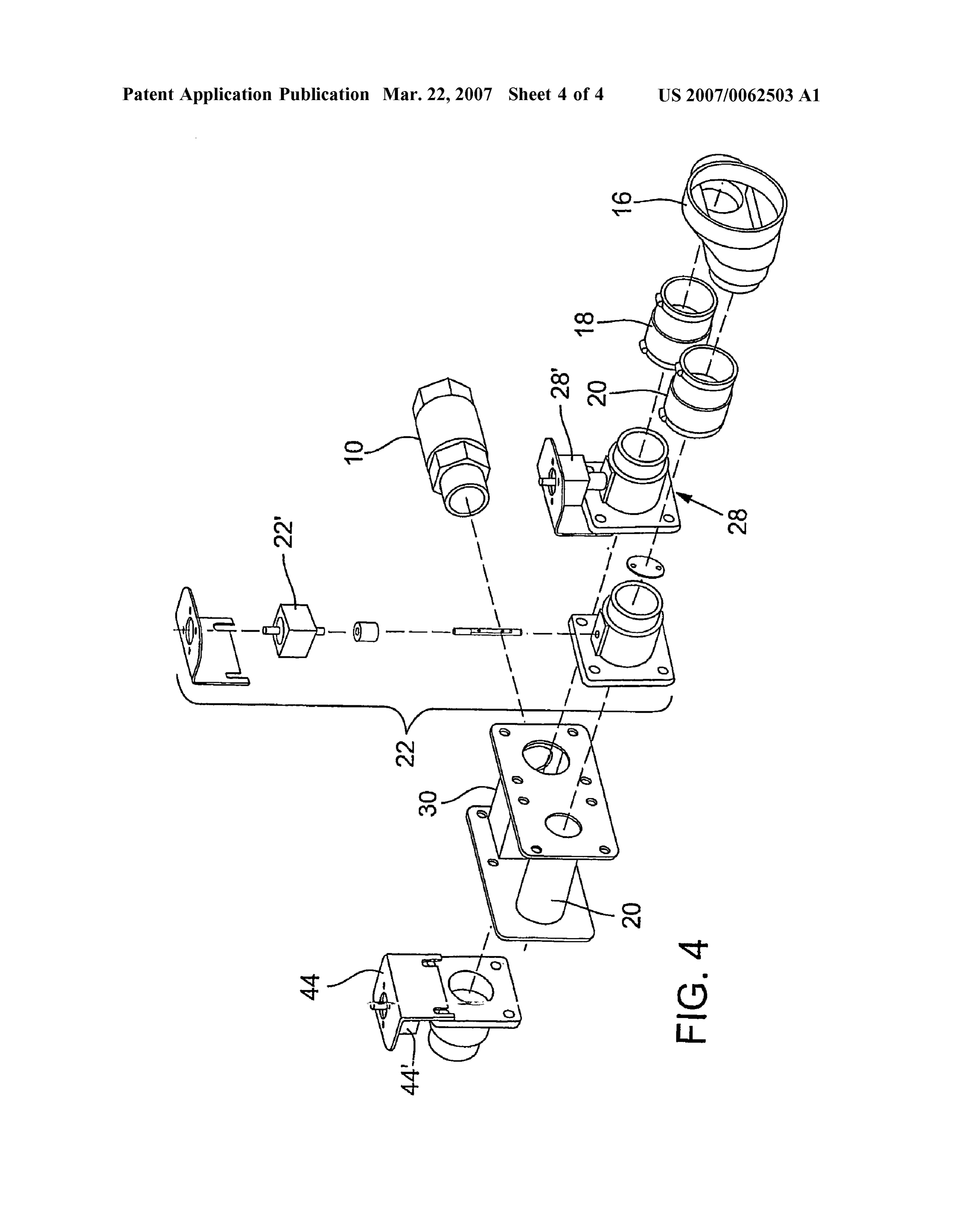
DESCRIPTION OF THE FIGURES bons from gasoline-produced engines currently available 0015 FIG. 1 is a schematic overview of a preferred cannot be total as such produces an undesired and unper embodiment of the invention; mitted emission of nitrogen oxides. Thus, one first deter mines the level of nitrogen oxide that is permitted and then 0016 FIG. 2 is an operational diagram of the system the lowest level of hydrocarbons that will stay within the utilized for the embodiment of FIG. 1; limits permitted for the restriction on nitrogen oxide. 0017 FIG. 3 is an exploded view of the vaporization tank 0026. It has further been determined that Odetectors for of FIG. 1; and detecting a level of O in the vehicle's exhaust and which have been incorporated into the exhaust system of later 0018 FIG. 4 is a further exploded view illustrating in model vehicles, are directly related to the level of hydro particular the control valves of the system of FIGS. 1 and 2. carbons in that same exhaust. Thus, one can determine what
DESCRIPTION OF THE PREFERRED
O' reading of the detector 14 produces the optimum fuel efficiency. For example, a desired hydrocarbon level may be
EMBODIMENT determined to exist when the O’ monitor produces a reading of 3 volts.
0019 Reference is made to FIG. 1, which provides a schematic overview of the components of a system in 0027. Returning to FIG. 1, it has been determined that accordance with the present invention. A gasoline-powered fuel efficiency is achieved by controlling the ratio of fuel engine as labeled, includes an intake port 10 connected to to-air mixture achieved at the mixing chamber 30 from the engine's throttle body. The engine, when operating, which the mixture enters the engine intake throttle body. It draws air and fuel through port 10. The engine includes an is known that the vapor-air-mixture directed into the mixing exhaust pipe 12 that is equipped with an O' sensor 14. The chamber 30 from conduit 42 is too rich, e.g., 1 part fuel to engine, intake port 10 and O' detector 14 may be standard 10 parts air, and of course the air only from conduit 18 has equipment provided for a conventional gasoline-driven Zero parts fuel. The desired mixture may be that which vehicle, and the remainder of the components of the illus achieves a 30 to 1 ratio, e.g., of 2 cubic feet of air, through trated embodiment are incorporated into the system to valve 28 for each cubic foot of air/vapor through valve 44. achieve the objectives of the present invention. 0028. Whereas the valves 28 and 44 can be set to achieve 0020 Item 16 represents an air box through which ambi the desired mixture at a given point in time, it has been ent air is drawn when operating the engine. Air conducting learned that many factors affect the ratio achieved in the conduits 18 and 20 from air box 16 provide the desired vapor/fuel mixture flowing through conduit 42. airflow to the remainder of the system as will be described. 0029 Assuming a specific hydrocarbon emission is 0021 Conduit 20 includes a valve 22 that controls the desired, a reading of the O detector will verify that this volume of air directed through conduit 20 and which is desired mixture has been achieved, as that reading also conveyed to a vapor producing tank 26 via the tanks top or indicates the hydrocarbons in the exhaust. As explained, a cover 24. fixed setting will not likely achieve the optimum ratio over any given period of time. Any temperature change, any 0022 Conduit 18 includes a valve 28 which controls the elevational change and even differences in fuel make up will Volume of ambient air that is directed into a mixing chamber skew the vapor/fuel mixture flowing from the tank 26 to the 3O. mixing chamber 30.
Page 8
US 2007/0062503 A1 Mar. 22, 2007
0030. Accordingly, the valves 22, 28 and 44 are operated peripheral edge of the top 24 includes bolt holes which line by stepper motors 22, 28' and 44 (illustrated in the flow up with bolt holes in flange portion 76 of baffle plate 66 and chart of FIG. 2 and in exploded perspective view in FIG. 4) with bolt holes in a flange 84 forming the peripheral edge of which stepper motors are automatically operated by com box 48. Bolts (not shown) are inserted through the aligned puter C. Computer C monitors the O’ and thus the hydro bolt holes to fasten the components together. A float 86 carbon emissions in exhaust 12 and should those readings contained in the box 48 determines the level of liquid indicate too high or too low hydrocarbons, the stepper gasoline contained in the box. The liquid gasoline enters the motors are activated by the computer to change the relative box through conduit 34 and a recycling conduit 90 is fluid volumes from conduit 18 and conduit 42. Should the provided to drain and/or circulate the gasoline in the vapor reading show a too high hydrocarbon level, the vapor?air izing tank 26 as may be desired.
flow of conduit 44 needs to be lessened, e.g., the valve 44 0037. In operation liquid gasoline is filled to a level of closed, or, e.g., the valve 28 opened, or, e.g., both closing of about 3/4 inch in the bottom of the box 48 which is above the valve 44 and opening of valve 28. position of the heater coils 50 and below the top of the baffle 0031. The adjustment may take place in stages, i.e., a 1° grid 56. The baffle grid 56 and baffle plate 62 primarily closing of valve 44, a re-reading of the O’ detector followed prevent sloshing of the gasoline during driving of the by repeated partial closing of valve 44 or alternatively the vehicle. As the liquid gasoline vaporizes (induced by the partial opening of valve 18 or a combination of both. Valve heating coil 50) air from inlet 78 is dispersed across the 22 can also be a factor as restricting air flow into conduit 20 liquid surface via baffle plates 72 and 68 which collects will slow the flow of air to the tank 26, thus to conduit 40, vapors 40 (see FIG. 1) and is then directed through outlet 80 while also diverting more airflow through valve 28. and to the mixing chamber 30 via conduit 42 as previously discussed.
0032. The structure as described enables the designer to design a system that will theoretically provide the desired 0038. As gasoline is vaporized and drawn from the result in fuel-to-air mixture (e.g., 1 to 30) as deemed Surface of the liquid gasoline, the gasoline level diminishes desirable, but then in recognition of the impact of small which is detected by the float 86. As determined desirable by environmental changes that produce Substantial deviations the system, the gasoline is replenished through inlet 34. in efficiency, provide automatic adjustments that are respon After Some period of time, the gasoline starts to become sive to real time readouts from an exhaust monitor, e.g., an contaminated (does not vaporize) and it is desirable to purge O detector. the tank. This can be done by converting the engine to gasoline use and drawing the residual gas of the tank 26 0033 Reference is now made to FIG. 3, which illustrates through the conventional gas injection system. It can also be the components of the vaporizing tank 26. The tank 26 simply drained into a holding tank and utilized for other consists of a metal box 48 having dimensions of about power equipment, e.g., a powered law mower. 4"x8"x12". Fitted to the bottom of the tank is a hot water coil 50 that includes an inlet 52 and outlet 54 which, when 0039. Whereas the above is considered a preferred assembled to the box 48, extends from the box via inlet 52" embodiment, the reader will readily understand that numer and outlet 54'. ous modifications and variations may be made without departing from the intended scope of the invention. Accord 0034 Seated onto the box bottom and over the coil 50 is ingly, the invention is not limited to the structure as a baffle grid 56. The plates of the baffle grid 56 include slots described above but fully encompasses the definitions of the 58 which enable the seating of the grid over the coil 50. appended claims.
Baffle grid 56 includes fastener tabs 60 and assembled to the fastener tabs 60 is a lower baffle plate 62 having spaced 1-13. (canceled) circular opening 64. The baffle plate 62 is seated below the 14. A fuel Supply assembly for a liquid fueled engine upper edge of box 48 (defined by flange 84) and affixed to including a combustion chamber for combusting fuel, and an the flange 84 is an upper baffle plate 66. Extending flanges exhaust for the combusted fuel, which assembly comprises: 68 of baffle plate 66 protrude laterally from the box and provide the means to secure the box 48 to the body of the a vaporizing tank, a quantity of a liquid fuel contained in vehicle. Upper flange 68 has rectangular openings 70. the tank, a heating source for heating the liquid fuel, and a temperature control for controlling the tempera 0035) Secured to the upper baffle plate 66 and in align ture of the liquid fuel as contained in the tank; ment with an air inlet to be described is a secondary upper baffle plate 72, reduced in size and secured to the upper plate said temperature control maintaining the temperature of 66 so as to cover a substantial portion of the opening 70'. the liquid fuel at a determined temperature to vaporize Provided in this secondary plate is a plurality of small holes, the liquid fuel, a conduit arrangement conveying the e.g., five holes 74 having a size of about a quarter inch in vaporized fuel from the tank, a primary source of diameter. Baffle plate 72 provides an impediment to airflow ambient air mixed with the vaporized fuel, said conduit from air inlet 78 and diverts the air flow laterally and arrangement conveying the intermixed ambient air and downwardly within the tank 26. vaporized fuel to the engine for combustion; and 0.036 Completing the assembly is the top or cover 24 an automatic control Substantially continuously monitor which has a complex shape which can be described as a ing the engine exhaust during operation of the engine distorted pyramid shape. The apex of the pyramid shape is and controlling the intermixing of the ambient air and positioned at one end whereat an air inlet 78 is provided A vaporized fuel to maintain a desired hydrocarbon level vapor air outlet 80 is provided at the same end but along the in the exhaust throughout changing environmental and side wall of the pyramid shape. A flange 82 forming the load demand conditions.
Page 9
US 2007/0062503 A1 Mar. 22, 2007
15. A fuel supply assembly as defined in claim 14 wherein a vaporizing tank containing a quantity of liquid fuel and a secondary Source of the ambient air is directed into and a fuel Supply Supplying said liquid fuel to the vapor through the tank for collecting and conveying an enriched izing tank;
vaporized fuel and air mixture into the conduit to be there said liquid fuel having a composition wherein vaporiza after combined with the primary source of ambient air. tion thereof readily occurs in a first portion and not in 16. A fuel supply assembly as defined in claim 15 wherein a residual portion;
a valve is provided for one or both of the primary source of ambient air and enriched vaporized fuel and air mixture, said a vaporizing mechanism for vaporizing the first portion one or both valves controlling the intermixing of said liquid fuel Supplied to the vaporizing tank; primary ambient air and vaporized fuel and air mixture.
17. A fuel supply assembly as defined in claim 16 wherein a first conduit arrangement conveying vaporized fuel from said control comprises a sensor sensing combustion exhaust the tank to the engine; and of said engine for determining the presence of hydrocarbons a purging conduit arrangement for periodic purging of the in said exhaust, said valve responsive to said sensor for residual portion.
modifying said intermixing and to thereby maintain a 23. A fuel supply assembly as defined in claim 22 wherein desired content of hydrocarbons in said exhaust. an alternate fuel Source provides fuel to the engine during 18. A fuel supply assembly as defined in claim 17 wherein the purging process.
said sensor senses O' emissions and said control determines the hydrocarbons based on the O' emissions. 24. A fuel supply assembly as defined in claim 22 wherein 19. A fuel supply assembly as defined in claim 15 wherein the engine is adapted to alternatively receive vaporized fuel a baffle arrangement in the tank directs air from said and liquid fuel, said purging conduit arrangement providing secondary source over the surface of the liquid fuel for said residual portion to said engine as the alternate fuel
SOUC.
stabilizing the temperature of said air as the air collects and conveys the vaporized fuel. 25. A fuel supply assembly as defined in claim 22, 20. A fuel supply assembly as defined in claim 14 wherein including a storage tank, said purging conduit conveying said fuel Source assembly is provided as an alternate fuel said residual portion to said storage tank for alternate use. Source to said engine. 26. A fuel Supply assembly as defined in claim 24, 21. A fuel supply assembly as defined in claim 20 wherein including a recycle control for a) vaporizing a portion of the the fuel as vaporized produces a residual fuel portion and a liquid fuel supplied to the vaporizing tank that will readily control for selectively providing vaporized fuel and/or a vaporize while running the engine on vaporized fuel; and b) liquid fuel to the combustion chamber, said residual fuel Switching engine operation to liquid fuel operation for conveyed to said combustion chamber as liquid fuel. purging the tank.
22. A fuel Supply assembly for an internal combustion engine comprising:
Provenance
- Collection
- Patents citing this work
- Original assignee
- VAPOR FUEL TECHNOLOGIES Inc
- Pages
- 9
- Method
- pdftotext (the PDF's own text layer) + pdftoppm 300dpi page scans
- Patent office record
- patents.google.com →
- Source
- Google Patents citing-documents table
- Inventors
- Raymond Bushnell; Danny Lewis; Robert Parry; VAPOR FUEL TECHNOLOGIES Inc
- Published
- 2007-03-22
- Transcribed from
- patentimages.storage.googleapis.com →