patent · US4702894
Hydrogen supply unit
27 October 1987
Page 1 — bibliographic record
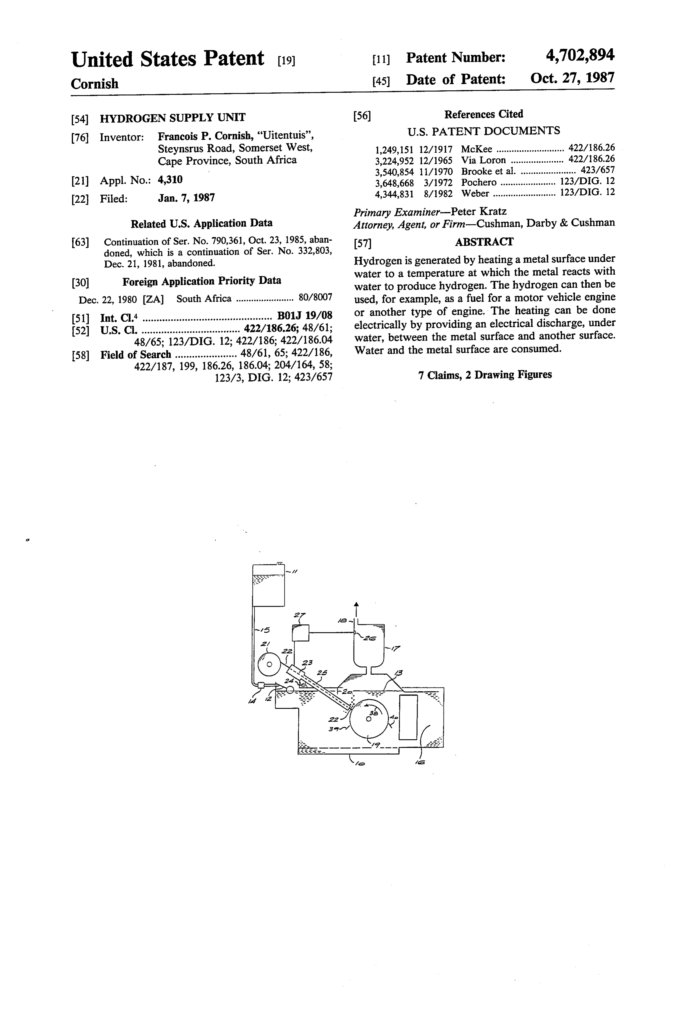
United States Patent (19) 11 Patent Number: 4,702,894 Cornish 45 Date of Patent: Oct. 27, 1987 54 HYDROGEN SUPPLY UNIT (56) References Cited 76 Inventor: Francois P. Cornish, "Uitentuis', U.S. PATENT DOCUMENTS Steynsrus Road, Somerset West, 1,249,151 12/1917 McKee ........................... 422/186.26 Cape Province, South Africa 3,224,952 12/1965 Via Loron ... 422/86.26 3,540,854 11/1970 Brooke et al. ...................... 423/657 21 Appl. No.: 4,310 3,648,668 3/1972 Pochero ..... 123/DIG. 12 22 Filed: Jan. 7, 1987 4,344,831 8/1982 Weber ......................... 123/DIG. 12 Primary Examiner-Peter Kratz
Related U.S. Application Data Attorney, Agent, or Firm-Cushman, Darby & Cushman 63) Continuation of Ser. No. 790,361, Oct. 23, 1985, aban 57 ABSTRACT doned, which is a continuation of Ser. No. 332,803,
Dec. 21, 1981, abandoned. Hydrogen is generated by heating a metal surface under (30) Foreign Application Priority Data water to a temperature at which the metal reacts with water to produce hydrogen. The hydrogen can then be
Dec. 22, 1980 ZA) South Africa ....................... 80/8007 used, for example, as a fuel for a motor vehicle engine 51) Int. Cl. .............................................. B01J 19/08 or another type of engine. The heating can be done 52 U.S. C. ................................... 422/186.26; 48/61; electrically by providing an electrical discharge, under 48/65; 123/DIG. 12; 422/186; 422/186.04 water, between the metal surface and another surface. 58) Field of Search ...................... 48/61, 65; 422/186, Water and the metal surface are consumed. 422/187, 199, 18626, 186.04; 204/164,58; 7 Claims, 2 Drawing Figures
Page 2
Drawing sheet — no readable text.
Page 3
hydrogen is fed to a small buffer store and as the pres
HYDROGEN SUPPLY UNIT sure in the store exceeds a predetermined level, the electrodes are separated so that hydrogen generation is
This is a continuation of application Ser. No. 790,361, interrupted. As the pressure drops to a certain level the filed Oct. 23, 1985, which was abandoned upon the 5 electrodes are again fed towards one another. filing thereof, which is a continuation of application BRIEF DESCRIPTION OF THE DRAWING
BACKGROUND OF THE INVENTION
The invention will now be further described, by way of example, with reference to the accompanying draw
This invention relates to hydrogen generation. 10 ing, in which:
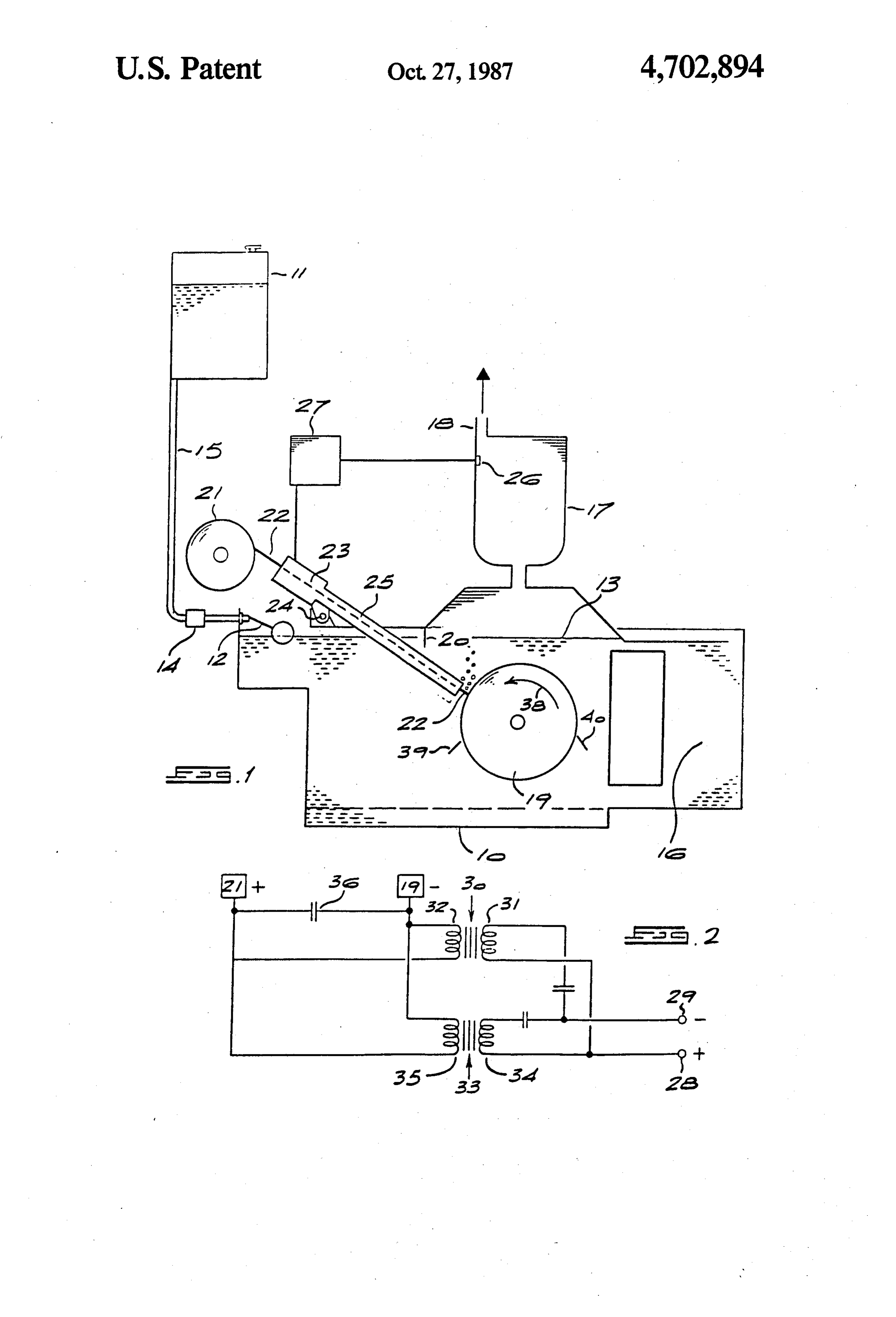
It has already been proposed to replace conventional FIG. 1 is a schematic representation of apparatus for fuels with hydrogen in the running of internal combus generating hydrogen, and suitable for powering a motor tion engines. Conventional proposals are to produce vehicle; and hydrogen by the electrolysis of water and then to store FIG. 2 shows a portion of an appropriate electrical the hydrogen in some form or another. No economi 15 circuit.
cally viable storage system for the highly explosive DESCRIPTION OF A PREFERRED hydrogen gas has yet been evolved. Whatever system is EMBODIMENT evolved would involve fairly massive tanks of some kind or another and precautions to prevent explosions. In the illustrated embodiment there is a generating The present invention is based on the desire of the tank 10 fed with water from a reservoir tank 11 through inventor to be able to provide hydrogen on demand a float valve 12 to keep the water level 13 in the tank 10 from materials which are in themselves safe to handle. substantially constant. When the apparatus is used in a SUMMARY OF THE INVENTION motor vehicle, the tank 11 can take the place of the conventional fuel tank of the vehicle with a pump 14 in
According to the invention a method of generating the line 15 to pump more water into the tank 10 when
hydrogen comprises the steps of exposing a fresh metal the position of the float 12 indicates that this is required. surface to water and heating the interface between the Water is consumed as hydrogen is generated, and so the metal surface and the water at least to the lowest tem tank 11 has to be periodically refilled. The generating perature at which the metal reacts with water to form a tank 10 is in communication with an air cooled heat metal oxide and hydrogen, the metal being chosen from 30 exchanger 16, which may take the same form as a con metals which are higher in the electromotive series than ventional motor car radiator.
hydrogen and having stable and safe handling charac The generating tank 10 is surmounted by a collecting teristics. vessel 17 from which hydrogen is drawn through a Preferably the metal surface is exposed and the inter restricted face heated by pressing an electrode of the relevant Inside the orifice
tank 18 of an internal combustion engine.
10 there is a drum 19 driven by any metal against a second electrode under water and apply suitable means to rotate ing a high voltage between the electrodes while, prefer 19 is made of aluminum.atAa constant depending speed. The drum flange 20 pro ably, moving the electrode surfaces relatively to one vides a water seal to the top left hand corner of the tank another.
10, so that
In other words in the preferred form of the invention 40 the vessel 17.that corner is not in gas communication with hydrogen is formed by creating an underwater electri cal discharge between two electrodes at least one of pullA coil 21 of aluminum wire 22 is fed through a push unit 23 of the kind used to feed welding wire to which is made of a metal as defined above.
The electrical discharge and the relative movement argon arc welding devices. The unit 23 is arranged to between the electrode surfaces ensure that fresh metal 45 feed the wire against the surface of the drum 19 and to surfaces are exposed to the water while at the same time traverse the wire along the length of the drum on a bar the discharge heats the interface between the electrodes 24. The wire passes along an insulating sleeve 25 which and the water to the required temperature at which the enters the tank 10 through a suitable wiper seal. In the vessel 17 there is a pressure sensor 26 con metal reacts with water to form its oxide and to liberate hydrogen. 50 nected to a control unit 27. When the pressure sensor Also in the preferred form of the invention the metal the senses a pressure above a predetermined value, it signals is aluminum which has the advantage that it is in rela thatcontrol unit 27 which in turn stops the unit 23 so wire is no longer fed towards the drum 19. When tively abundant supply, relatively cheap, is formed with the pressure drops again, feeding is resumed. a protective oxide layer on its exposed surfaces and reacts with water at a relatively low temperature. Alu 55 In use, the coil 21 is connected to the high tension minum wire fed against a rotating aluminum drum has side of two ignition coils or transformers 30 and 33. These transformers have primary windings 31 and 34 been found to give excellent results to provide hydro and secondary, high tension windings 32 and 35. A gen for powering small internal combustion engines.
A convenient way of securing the high voltage re capacitor 36 is connected across the high tension con quired is to employ the conventional distributor and 60 nections. The terminais 28 and 29 are connected to a coil arrangement which provides the sparking for an conventional vehicle battery.
internal combustion engine. Two coils in parallel fed At the point of contact between the end of the wire from a common distributor has been found to give ex 22 and the drum 19 an electrical discharge takes place. cellent results. Other methods of generating high volt As a result the adjacent metal surfaces are heated to a ages from the battery or the drive shaft of an internal 65 high temperature, the protective oxide film which natu combustion engine may also be used. rally forms on exposed aluminium surfaces is disrupted, The method of the invention lends itself in an excel and the exposed aluminium surfaces react with the wa lent manner to supply hydrogen on demand. In this case ter. In fact the electrochemical situation at the interface
Page 4
is such that the wire 22 is consumed, with the following a metal surface of said first metal element being dis reaction taking place. posed adjacent to a metal surface of said second metal element with the metal substrates of both surfaces being in an electrical circuit to form re spective positive and negative electrodes between
As a result, hydrogen bubbles from the contact point which an electrical discharge may be made to take while the aluminum oxide collects as a white powder in place;
the base of the tank 10. A grid 37 in the bottom of the means for moving said metal surface of said first tank allows the powder to pass through, and then keeps metal element continuously toward said metal sur the powder substantially free from currents in the tank 10 face of said second metal element; 10. The hydrogen passes through the vessel 17 and the means for providing a current in said electrical circuit orifice 18 to the carburettor of an internal combustion which includes said metal surfaces of sufficient engine. intensity such that an electrical discharge between There may be a tendency for bubbles of hydrogen to said positive and negative electrodes occurs caus adhere to the surface of the drum 19 which rotates in 15 ing the metal of at least one of said electrodes to the direction indicated by the arrow 38. To prevent this react with water in the vicinity thereof resulting in happening, a wiper blade 39 can be located in the posi the formation of a metal oxide and the generation tion shown in FIG. 1, so as to separate any adhering of hydrogen; and bubbles from the drum surface. means for collecting the generated hydrogen. Alternatively, a wiper blade 40 may be arranged on 20 2. Apparatus as claimed in claim 1, wherein the first the opposite side of the drum. In this case a small vol metal element is aluminum.
ume of hydrogen gas may collect beneath this blade and 3. Apparatus as claimed in claim 1, wherein the sec it may be possible to pivot the blade 40, thus releasing ond metal surface is aluminum.
this pocket of hydrogen in order to facilitate start-up of 25 4. Apparatus as claimed in claim 1, wherein the tank an engine fueled by the hydrogen. w is connected to a heat exchanger, so that water can It may be possible to use salt water in the tank 10, circulate from the tank, through the heat exchanger, and back to the tank.
rather than fresh water.
The drum 19 preferably rotates at a speed between 5. Apparatus for generating hydrogen comprising a 400 and 700 rpm, but the rotation may be as slow as 50 30 metalcontaining tank water, a first metal surface and a second surface arranged in the tank, said first metal sur rpm.
During operation, the temperature of the water in the face being connected to said second metal surface in an tank 10 may rise as high as 95 C., although it is likely electrical circuit to form a positive and a negative elec that a unit mounted in a moving vehicle, for example, trode between which an electrical discharge may be will be able to maintain the water at a lower tempera made to take place, means for moving the first metal 35 surface relative to the second metal surface, means for tre,
A unit substantially as shown in the drawings has providing a current in the electrical circuit formed by the connection of the first and second metal surfaces been used to drive a 500 cc motor cycle engine. The such current being of sufficient intensity that when wire 22 had a diameter of 1,6 mm and was of commer applied to the circuit, an electrical discharge between cial purity (98% AI). The unit produced over 1000 cc of 40 the electrodes will occur causing the elctrodes to react hydrogen a minute, with an aluminium wire consump with water in the tion rate of 140 to 180 cm per minute. The rate of depo ation of hydrogenvicinity thereof resulting in the gener and means for collecting the gener sition of aluminium oxide was about 4 kilograms per 500 ated hydrogen, and wherein the first metal surface is a kilometers traveled. wire and the second metal surface is a drum, the drun Conventional modifications were made to the carbu 45 being mounted for rotation and the wire being sup rettor to enable the engine to run on a mixture of hydro ported so that it approaches the cyclindrical surface of gen and air. the drum at an angle to a tangent to the drum surface. The wire 22 carries a voltage of about 18000 volts 6. Apparatus as claimed in claim 5, wherein the wire with a current of about 1 amp. is supported by a device which continuously feeds the The invention may equally be used to power station 50 wire, as it is consumed, towards the drum surface. ary industrial engines, as well as motor vehicle engines. 7. Apparatus as claimed in claim 6, wherein means are I claim: provided for sensing the pressure of hydrogen gas in the 1. Apparatus for generating hydrogen comprising: chamber and for regulating the feed rate of the wire a tank for containing water; feeding device in accordance with the sensed pressure, a first metal element and a second metal element 55 to control the hydrogen output.
disposed in said tank; k : :
Provenance
- Collection
- Cited prior art
- Original PDF
- patentimages.storage.googleapis.com →
- Filed
- 1987-01-07
- Pages
- 4
- Method
- pdftotext (the PDF's own text layer) + pdftoppm 300dpi page scans
- Source
- Google Patents bibliographic record
- Granted
- 1987-10-27
- Inventors
- Francois P. Cornish
- Transcribed from
- patentimages.storage.googleapis.com →