patent · US20070277791A1
system for improving fuel utilization
6 December 2007
Page 1
(19) United States (12) Patent Application Publication (10) Pub. No.: US 2007/0277791 A1
Bushnell et al. (43) Pub. Date: Dec. 6, 2007 (54) SYSTEM FOR IMPROVING FUEL (21) Appl. No.: 11/421,698
UTILIZATION
(75) Inventors: Raymond Bryce Bushnell, Publication Classification Beavercreek, OR (US); Anthony
Robert Lewis, Beavercreek, OR F02G 5/00 (2006.01)
(US) FO2B 43/00 (2006.01)
Correspondence Address: (52) U.S. Cl. ........................................ 123/557; 123/527 SCHWABE, WILLIAMSON & WYATT, P.C. (57) ABSTRACT
PACWEST CENTER, SUITE 1900
1211 SW FIFTHAVENUE A vapor fuel air mixture Supply system for a combustion PORTLAND, OR 97204 engine, whereby the mixture of air and fuel vapor is elevated in temperature prior to combustion. The liquid fuel may be (73) Assignee: VAPORFUEL vaporized in a fractionation process and further heated to TECHNOLOGIES, LLC, enhance flame speed combustion and improve efficiency of
14 12 36 T1 WYY /
Page 2
Drawing sheet — no readable text.
Page 3
Patent Application Publication Dec. 6, 2007 Sheet 2 of 2 US 2007/0277791 A1
rt rst 3 S S S R rt
army
als
to so N. oo on 9 S. cy wir in No in co
CO2 IN EXHAUST IN% O2 IN EXHAUST N X,
Page 4
US 2007/0277791 A1 Dec. 6, 2007
SYSTEM FOR IMPROVING FUEL mixed with the fuel vapors to lean out the mixture to achieve UTILIZATION the desired air:fuel ratio. This may cause the fuel vapors to in part condense and form liquid droplets. To help achieve
FIELD OF INVENTION improved performance, embodiments of the present inven 0001. This invention relates to a system for providing tion may help to avoid Such condensation by elevating the vaporized fuel to engines. temperature of the vapor and air mixture to a point above that required for vaporization so that the fuel remains in a
BACKGROUND AND BRIEF DESCRIPTION vaporized form. In other embodiments, the ambient air that is to be mixed with the vaporized fuel may be preheated.
0002 Vehicles powered by vaporized fuel, such as gaso 0009 Further such heating of the air supply, vaporized line, have been the Subject of numerous patents over many fuel, and/or air-vaporized fuel mixture may also further years. Examples include co-owned U.S. Pat. Nos. 6,681,749 enhance the flame speed of the fuel/air mixture. This in turn and 6,907.866. The disclosures of such patents are incorpo can extend the “lean limit” (i.e., the highest air: fuel ratio rated herein by reference. where the engine can perform satisfactorily, without exces 0003 Vaporizing the fuel prior to entrance to the cylinder sive loss of power, misfire, and/or unacceptable hydrocarbon can lead to improved performance, particularly with respect emissions). This extension of the lean limit may have several to Substantially improved fuel economy. Running an engine advantages, including, but not limited to: (1) It improves “lean' (i.e., at an air to fuel ratio of greater than 15:1) can fuel economy. (2) It decreases the amount of NOx produced. lead to improved fuel economy. Accordingly, vaporizing the (0010. It is further helpful to elevate the temperature of the fuel prior to entering the combustion chamber of the engine ambient air that is mixed with and conveys the fuel vapors allows the engine to run at much higher air to fuel ratios than from the vaporization chamber prior to entry into the com a conventional engine, which in turn leads to improved fuel bustion chamber of the engine. As will be discussed more economy. fully hereafter, the mixed air/fuel from the vaporization 0004. It has been learned, however, that a potential issue chamber is further diluted with ambient air, and such further may arise with operating at the larger air-to-fuel ratios, in ambient air is also heated whereby the diluted vaporized fuel that an undesired increase NO, emissions may result. This is mixture, upon entering the combustion chamber, is elevated due in part to the fact that the conventional catalyst on an above the temperature of the non-diluted mixture conveyed automobile with a gasoline engine is designed to remove from the vaporization chamber. As described above, this NO with the engine operating at around a 15:1 air/fuel ratio. heating of the air/fuel mixture may help to achieve some of 0005. However, applicants have found that the amount of the benefits that improve engine performance, including NO, actually produced by the engine decreases as the preventing condensation of the fuel and increasing the flame air/fuel ratio increases, and the increase in emissions is a speed.
result of the fact that the catalyst cannot reduce even the smaller amount of NO produced under these conditions. BRIEF DESCRIPTION OF THE DRAWINGS Thus, applicants have learned that by operating an engine at a sufficiently high air/fuel ratio, the amount of NO, formed 0011 Embodiments in accordance with the present would be sufficiently low such that the engine could meet invention will be more fully understood and appreciated by emissions requirements, even with a catalyst that was not reference to the following detailed description and the operating at its optimal conditions (e.g. air to fuel ratio). accompanying drawings.
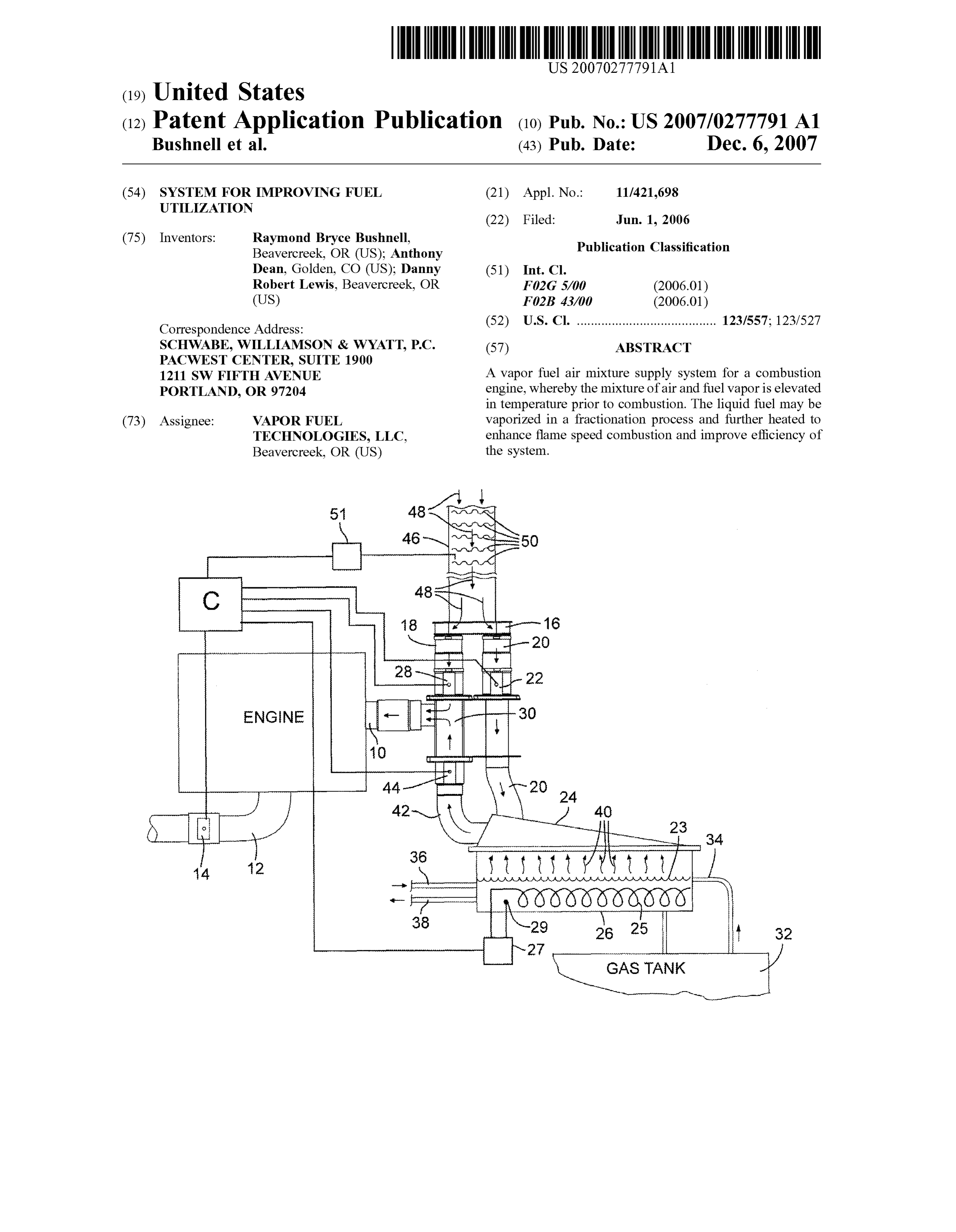
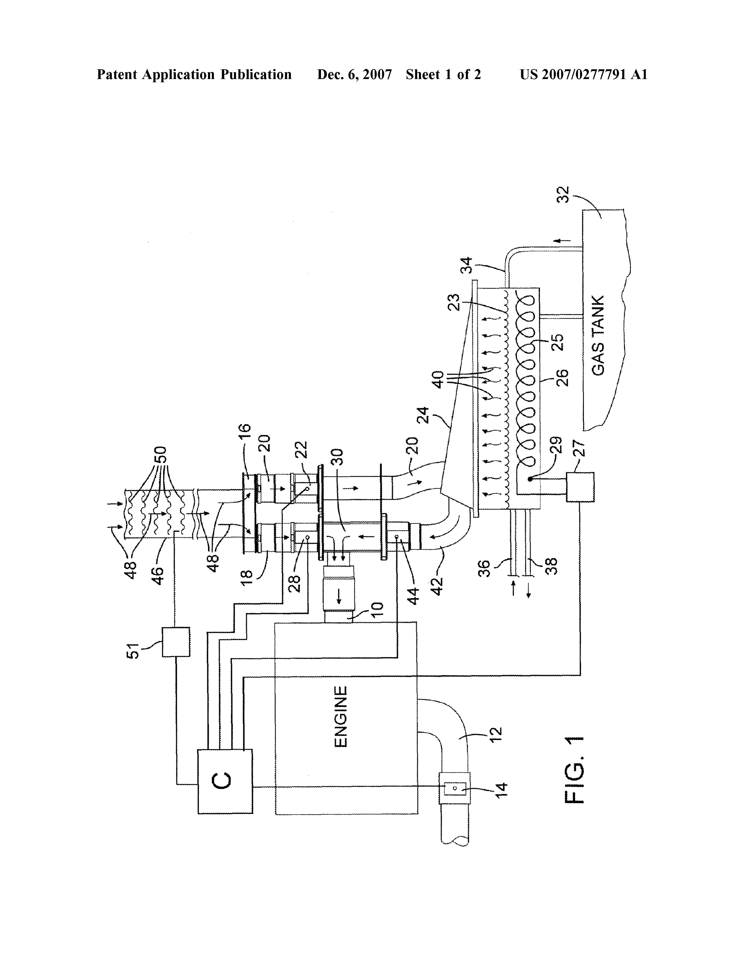
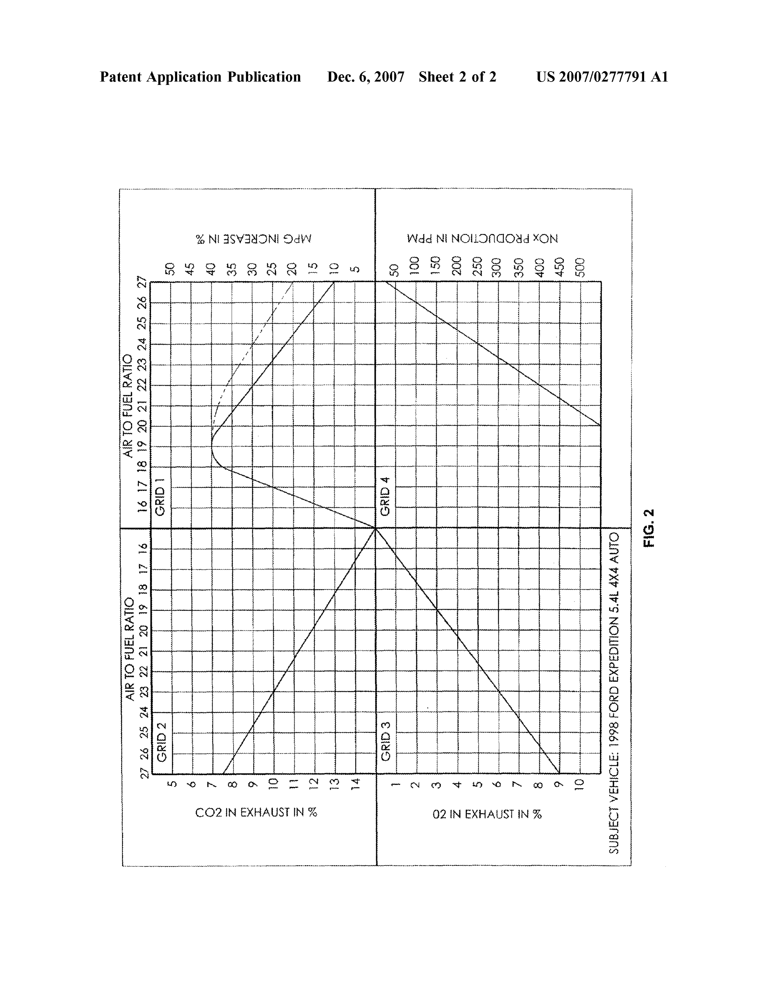
0006 Embodiments of the present invention disclose 0012 FIG. 1 is a schematic illustration of a vaporized ways to operate a combustion engine at these higher air-fuel fuel engine including a source of heated ambient air in ratio (e.g., about greater than 21:1) such that the level of NO, accordance with the invention; and emitted can satisfy existing regulations. One of the advan 0013 FIG. 2 is a compilation of charts demonstrating the tages of such operation may be that the high air-fuel ratio can benefits of the invention.
allow for Substantial improvements in fuel economy. As catalyst technology employed in vehicles improves, how DETAILED DESCRIPTION OF EMBODIMENTS ever, the embodiments of the present invention may be used OF THE INVENTION to improve fuel economy with other air-fuel ratios (e.g., between 15:1 and 21:1) and still meet emission standards. 0014. In the following detailed description, reference is 0007 Liquid fuel may be viewed as being comprised of made to the accompanying drawings which form a part fractions that may vaporize at different temperatures. This hereof and in which is shown by way of illustration embodi vaporization can be achieved by initial heating of liquid fuel ments in which the invention may be practiced. It is to be at a first temperature (e.g. 70° F.) and Subsequently increas understood that other embodiments may be utilized and ing the temperature as the differing fractions of the liquid structural or logical changes may be made without departing fuel are vaporized and/or decreased vaporization of the fuel from the scope of the present invention. Therefore, the is detected. Referred to as fractionation, applicants have following detailed description is not to be taken in a limiting learned that generally sequentially Supplying fractions of sense, and the scope of embodiments in accordance with the vapors to the combustion chamber may improve efficiency. present invention is defined by the appended claims and 0008 Further, through observation and testing, appli their equivalents.
cants have discovered that vaporized fuel being conveyed to 00.15 Various operations may be described as multiple the engine's combustion chamber may be subject to con discrete operations in turn, in a manner that may be helpful densation during Such conveyance. This can happen, for in understanding embodiments of the present invention; example, as a result of ambient air that has a temperature however, the order of description should not be construed to below that of the liquid fuel vaporization temperature being imply that these operations are order dependent.
Page 5
US 2007/0277791 A1 Dec. 6, 2007
0016. The description may use orientation and/or per directed out through conduit 42 to the mixing chamber 30. spective-based descriptions such as up/down, back/front, In one embodiment, the flow of the air-fuel vapor through and top/bottom. Such descriptions are merely used to facili conduit 20 may be controlled by valve 44. tate the discussion and are not intended to restrict the 0025. In one embodiment, the air-fuel vapor mixture of application of embodiments of the present invention. conduit 42 may be too rich, and must be further leaned with 0017. The description may use phrases such as “in an air. When this is the case, the air-fuel mixture may be embodiment,” or “in embodiments.” Such phrases may each intermixed (e.g. further leaned) in mixing chamber 30 with refer to one or more of the same or different embodiments. ambient air from conduit 18, and further directed through the Furthermore, the terms “comprising,” “including,” “hav intake port 10 and from there into the combustion chamber ing, and the like, as used with respect to embodiments of of the engine. The desired air to fuel ratio being supplied to the present invention, are synonymous. the combustion engine may thus be controlled in several 0018. The phrase “A/B” means “A or B.’ The phrase “A ways, including, but not limited to controlling the air Supply and/or B means “(A), (B), or (A and B). The phrase “at to the combustion chamber, controlling the air Supply to the least one of A, B and C’ means “(A), (B), (C), (A and B). mixing chamber, and increasing the rate of vaporization of (A and C), (B and C) or (A, B and C).” The phrase “(A) B' the liquid fuel.
means “(B) or (AB), that is, A is optional. 0026. In one embodiment, it may be desirable to achieve 0019. The terms “coupled' and “connected,” along with an air to fuel ratio of at or above 26:1, which should yield their derivatives, may be used. It should be understood that NOx emissions that are substantially lower than those these terms are not intended as synonyms for each other. obtained at a lower air:fuel ratio and will meet today's Rather, in particular embodiments, “connected may be used emission standards. In another embodiment, operating with to indicate that two or more elements are in direct physical an air to fuel ratio below 26:1 will likely yield NOx or electrical contact with each other. “Coupled may mean emissions above today's acceptable emission standards. that two or more elements are in direct physical or electrical However, as catalyst technology or engine improvements contact. However, “coupled may also mean that two or (e.g., EGR) are employed, the air to fuel ratio achieved by more elements are not in direct contact with each other, but embodiments of the present invention may be lower, yield yet still cooperate or interact with each other. ing acceptable NOx levels, while still resulting improved 0020 Reference is made to FIG.1, which provides a fuel economy.
schematic overview of the components of a system in 0027 Assuming a specific hydrocarbon emission is accordance with embodiments of the present invention. A desired, a reading of the emissions sensor may help to verify powered engine as labeled, may include an intake port 10 that the desired air to fuel ratio is achieved. However, it can connected to the engine's throttle body. The engine, when be appreciated that a fixed setting will not likely achieve the operating, may draw air and fuel through port 10. The engine optimum performance over any given period of time. Any may also includes an exhaust pipe 12 that is equipped with temperature change, any elevational change and even dif a senor 14 adapted to detect O2 and/or other emissions. ferences in fuel make up may skew the vapor/fuel mixture 0021. In one embodiment, air box 16 may allow the flowing from the tank 26 to the mixing chamber 30. Supply of ambient air to the system when operating the 0028. Accordingly, the valves 22, 28, and 44 may be engine. Air conducting conduits 18 and 20 coupled to airbox operated by, for example, stepper motors (not shown) con 16 may bifurcate the inflow of ambient air and provides the trolled by computer C. Computer C may monitor the emis desired air supply to the remainder of the system. In other sions in exhaust 12 and should those readings indicate that embodiments, the conduits 18 and 20 may be coupled to the levels of hydrocarbons are too high or too low, the separate air supplies. Conduit 20 may include a valve 22 computer may activate the appropriate stepper motors to which controls the volume of air directed through conduit change the relative fluid volumes of air from conduit 18, air 20. Conduit 20 may be further coupled to vaporizing cham from conduit 20 and the air-fuel vapor mixture of conduit 42. ber 26 via, e.g., the top or cover 24, and thus configured to Should the reading show a too high hydrocarbon level, the Supply air to vaporizing chamber 26. vapor/air flow of conduit 44 may need to be lessened, e.g., 0022 Conduit 18 may be coupled to a mixing chamber the valve 44 may be closed, the valve 28 opened, and or both 30 and include a valve 28 that may be configured to controls closing of valve 44 and opening of valve 28. the volume of ambient supplied to mixing chamber 30. 0029. These adjustments may take place in stages (e.g., a Mixing chamber 30 may be any volume where air and vapor partial closing of valve 44, a rereading of the emissions fuel are brought together, Such as a chamber, confluence, and sensor followed by repeated further partial closing of valve the like. 44, or alternatively the partial opening of valve 28, or a 0023. In one embodiment, vaporization chamber 26 may combination of both). In one embodiment, valve 22 can also include a flow control apparatus e.g. baffles, which can be a factor, as restricting air flow into conduit 20 will slow direct airflow from conduit 20 through the vaporization the flow of air to the tank 26, thus to conduit 42, while also chamber and into conduit 42. Liquid fuel 23 may be drawn diverting more air flow through valve 28. from a fuel tank 32 via conduit 34. Heating element 25 may 0030 Embodiments of the present invention may include be coupled to vaporization chamber 26 and adapted to one or more additional heat sources that can allow for controllably heat the liquid fuel to generate fuel vapors 40. heating the air that may be Supplied to the vaporization tank, A number of heating sources may be used to controllably the air that may be Supplied to the mixing chamber, and/or heat the liquid fuel, including, but not limited to engine the air and vaporized fuel mixture exiting the vaporizing component proximity, engine fluids (water, oil, etc.), elec chamber.
trical circuits, and other independent heating devices. 0031. In one embodiment, a heat source 46 may control 0024. The vapors 40 may be carried by the air flow from the temperature of the air flow 48 and elevate the tempera air conduit 20, such that the air-fuel vapor mixture may be ture of the air Supply as deemed necessary based on the
Page 6
US 2007/0277791 A1 Dec. 6, 2007
content of the emissions. As illustrated, heat source 46 may engine via intake port 10. This may help to improve burning be heating coils 50 disposed within the air flow 48. How efficiency as well as prevent condensation in the mixing ever, embodiments of the present invention may include a chamber itself.
variety of heat sources, including heat generated from dif 0038 Elevation of the temperature of vapor fuel mixture ferent components of the engine (e.g. the engine's manifold being directed through intake port 10 can be achieved and/or and/or engine fluids), as well as independent heat sources. augmented in a variety of ways that are separate from, 0032. However provided, upon traversing the heat source complementary to and/or in addition to those described 46, the air inflow 48 may be controllably elevated in above. In one embodiment, the relationship of the heat temperature (e.g., controllably raising the typical ambient air Sources to the vaporization chamber and the mixing chamber temperature from a range of about 60° to 80° F. to a can impact the heating of the air-fuel vapor mixture. For temperature of about 100° to 120°F). Again, the amount the example, if the relationship of the heat source 46 to the temperature of the air Supply may vary depending on vaporization chamber 26, as compared to the mixing cham ber 30 results in a longer conveyance path to the vaporiza emission content and conditions, and may be controlled tion chamber, this may result in an undesired drop in the based thereon.
temperature. A shorter distance through conduit 18 into 0033. In one embodiment, control 27 may control the mixing chamber 30 may thus provide the desired elevation heat generation of heat element 25. Control 27 may also be in temperature to the vaporized fuel conveyed to the com coupled to and controlled by the computer C depending on bustion chamber.
the response in part to the emission detections by sensor 14. 0039. In various other embodiments, heat may be applied In one embodiment, the liquid fuel in the vaporization tank to various components of the system to help elevate the 26 may be vaporized and mixed with the air supply from temperature of the air-fuel mixture prior to entering the conduit 20. This mixture may be directed to the mixing combustion chamber to help improve efficiency and/or to chamber 30 and further to the combustion chamber of the help prevent condensation. Further, other alternatives are engine. As discussed above, the temperature of the liquid available and of course separate heat sources may be utilized fuel may be increased enough to vaporize one fraction of the at different locations in the system. fuel 23 at a time. The temperature of the fuel 23 may then 0040. Reference is now made to FIG. 2 illustrates some be raised to initiate vaporization of a second fraction, which of the beneficial result that may be achieved by employing in turn may be carried out of the vaporization chamber with embodiments of the present invention. An example of the the air Supply, and so on. combustion of vaporized fuel without the added heat is 0034. While the air-fuel mixture is being conveyed to the shown in Solid lines in graph 1 and the heated fuel is shown mixing chamber, there may be the possibility that a part of in dashed lines. By increasing the temperature of the vapor, the mixture may condense to liquid form prior to entering the ratio of air to fuel can be increased substantially without the combustion chamber. In one embodiment, to prevent materially sacrificing the desired fuel economy. A distinct condensation from taking place (e.g. in the path through benefit of such elevation is the reduction of nitrogen oxide conduit 42 and mixing chamber 30), the air from conduit 20 as demonstrated in graph 4. Graphs 2 and 3 illustrate the may be elevated e.g. by heat source 46 to establish a comparable reduction of CO and increase in O. temperature of the air at or above the temperature of the 0041 Although certain embodiments have been illus vapor 40. This may prevent condensation as the fuel is trated and described herein for purposes of description of the carried through conduit 42 and into the mixing chamber 30. preferred embodiment, it will be appreciated by those of A too high temperature of air from conduit 20, however, ordinary skill in the art that a wide variety of alternate and/or could undesirably overheat the liquid fuel 23 producing an equivalent embodiments or implementations calculated to undesired high rate of vaporization, which in certain achieve the same purposes may be substituted for the embodiments, may affect the fractionation of the liquid fuel embodiments shown and described without departing from and alter the characteristics of the mixture. Thus the tem the scope of the present invention. Those with skill in the art perature of the air entering the vaporization chamber may be will readily appreciate that embodiments in accordance with controlled to avoid this occurrence. the present invention may be implemented in a very wide 0035. Because the air temperature may drop as it is variety of ways. This application is intended to cover any conveyed from the heat Source 46 and because the process adaptations or variations of the embodiments discussed of vaporization itself extracts energy, in one embodiment, herein. Therefore, it is manifestly intended that embodi there may be a balancing of the elevation of the air tem ments in accordance with the present invention be limited perature. This may be monitored and controlled by tempera only by the claims and the equivalents thereof. ture probes and controls.
0036. In one embodiment, a heat source may be coupled What is claimed is:
to the conduit coupling the vaporization chamber and the 1. A system for a vaporized fuel engine, comprising: mixing chamber and/or the combustion chamber. Such a a combustion chamber wherein a fuel-air mixture is heat source may be controlled to in order to keep the ignited, and including an exhaust for the resulting temperature of the mixture sufficiently elevated and to resist emissions;
condensation. In Such a case, the air-vapor fuel mix may be a vaporized fuel source, an air source, and controls Subjected to a further temperature increase without concern controlling mixture of vaporized fuel from the fuel for impacting the fractionation process. Source and air from the air source and directing the 0037. In one embodiment, the temperature of the air mixture to the combustion chamber, and supply to the mixing chamber 30 may be elevated by heat a first heat source configured to elevate the temperature of source 46 in order to further heat the air-fuel mixture prior the vaporized fuel prior to conveyance into the engine's to being conveyed into the combustion chamber of the combustion chamber.
Page 7
US 2007/0277791 A1 Dec. 6, 2007
2. A system as defined in claim 1 wherein the vaporized 12. The vapor fuel supply system of claim 9 wherein the fuel Source includes a second heat Source configured to heat vaporization chamber and the mixing chamber are coupled liquid fuel contained in a vaporization chamber to create the to the same air source.
vaporized fuel. 13. The vapor fuel supply system of claim 9, wherein the 3. A system as defined in claim 2, wherein the second heat liquid fuel heat Source is configured to controllably cause Source is controlled in order to increase and/or decrease the fractionation of a liquid fuel. temperature of the liquid fuel to achieve a desired fraction 14. A vaporized fuel engine system comprising: ation of the liquid fuel. a quantity of liquid fuel contained in a vaporization tank, 4. A system as defined in claim 2 wherein a first air flow said liquid fuel comprising fractions having varying from the air source is directed to the vaporization chamber, vaporization temperatures; and the first heat source configured to heat the first air flow a controllable heat Source for heating said quantity of prior to entering said vaporization chamber. liquid fuel to sequentially vaporize said fractions; 5. A system as defined in claim 4 wherein the air supplied conduits for conveying ambient air to be intermixed with by the air source is bifurcated into the first air flow and a the vaporized fuel fractions to form an air to vaporized second air flow such that the second air flow may also be fuel mixture of a determined ratio and then to said mixed with the mixture in a mixing chamber. engine for combustion; and 6. A system as defined in claim 4 wherein a second air a secondary heat source for heating said mixture of flow from a second air source is mixed with the mixture in ambient air and vaporized fractions to a further a mixing chamber prior to entry into the combustion cham elevated temperature.
ber. 15. A method of supplying preheated vaporized fuel to a 7. A system as defined in claim 4, wherein the temperature combustion engine, comprising:
of the mixture leaving the vaporization chamber is elevated vaporizing liquid fuel to form a vaporized fuel; by a third heat source. mixing said vaporized fuel with an air Supply to form a 8. A vaporized fuel system for an engine comprising: mixture having a desired air to fuel ratio; and a quantity of liquid fuel contained in a vaporization heating the air Supply, the vaporized fuel and/or the chamber and a controllable heat source for heating said mixture to a temperature at or above a vaporizing quantity of liquid fuel; temperature of the liquid fuel prior to conveyance to the said liquid fuel comprising fractions having varying tem combustion engine.
peratures for vaporization and said controllable heat 16. The method of claim 15, wherein said air supply Source adapted to increase the temperature of the liquid includes a first air supply and wherein said mixing said fuel for sequentially vaporizing the fractions; vaporized fuel with said air supply includes: conduits for conveying ambient air to be intermixed with conveying said first air Supply to a vaporization chamber the vaporized fractions and then to said engine for creating a first mixture having an air to fuel ratio; and combustion; and conveying the resulting mixture towards said combustion a further heat source for heating said mixture of ambient engine.
air and vaporized fractions to a further elevated tem 17. The method of claim 16, further comprising elevating perature. the temperature of the first air supply prior to entry into the 9. A vapor fuel supply system for a combustion chamber, vaporization chamber.
comprising: 18. The method of claim 16, wherein said air supply a mixing chamber coupled to the combustion chamber; includes a second air supply, and further comprising: a vaporized fuel source coupled to the mixing chamber, conveying said first mixture to a mixing chamber; the vaporized fuel source including a vaporization conveying the second air Supply to said mixing chamber; chamber and a liquid fuel heat Source adapted to and generate vaporized fuel; mixing said first mixture with said second air Supply to one or more air sources coupled to and configured to form the desired air to fuel ratio. provide an air Supply to the vaporization chamber 19. The method of claim 18, further comprising elevating and/or the mixing chamber, and the temperature of the first mixture prior to entry into the an air Supply heat Source configured to controllably mixing chamber.
elevate the temperature of the air supply prior to the 20. The method of claim 18, further comprising elevating entry into the mixing chamber and/or the vaporization the temperature of the second air Supply prior to the con tank. veying to the mixing chamber.
10. The vapor fuel supply system of claim 9, further 21. The method of claim 15, wherein the vaporizing liquid comprising a vaporized fuel heat source configured to fuel comprises:
elevate the temperature of the vaporized fuel at a point Supplying liquid fuel to a vaporizing chamber having a downstream of the vaporization chamber and upstream of heating element; and the combustion chamber. elevating the temperature of the liquid fuel with the 11. The vapor fuel supply system of claim 9, wherein the heating element to cause fractionation of the liquid fuel temperature of the air supply from the air source to the resulting in fractions of vaporized fuel. mixing chamber is controlled to elevate the temperature of 22. The method of claim 21, further comprising: the vaporized fuel entering the mixing chamber to a tem conveying a first air supply to the vaporization; and perature above the temperature of the vaporized fuel leaving sequentially conveying said fractions and first air Supply the vaporization chamber. towards the combustion engine.
Page 8
US 2007/0277791 A1 Dec. 6, 2007
23. The method of claim 22, further comprising elevating 25. The method of claim 22, further comprising mixing a the temperature of the first air Supply prior to entering the second air Supply having an elevated temperature with said vaporizing chamber. first air Supply and fractions elevating the temperature of the 24. The method of claim 22, further comprising elevating first air Supply and said fractions. the temperature of the first air Supply and said fractions
Subsequent to the vaporization chamber. k . . . .

Provenance
- Collection
- Patents citing this work
- Original assignee
- Vapor Fuel Tech Inc
- Pages
- 8
- Method
- pdftotext (the PDF's own text layer) + pdftoppm 300dpi page scans
- Patent office record
- patents.google.com →
- Source
- Google Patents citing-documents table
- Inventors
- Raymond Bryce Bushnell; Anthony Dean; Danny Robert Lewis; Vapor Fuel Tech LLC
- Published
- 2007-12-06
- Transcribed from
- patentimages.storage.googleapis.com →