patent · US20080032245A1
Fuel utilization
7 February 2008
Page 1 — bibliographic record
(19) United States (12) Patent Application Publication (10) Pub. No.: US 2008/003224.5 A1
Bushnell et al. (43) Pub. Date: Feb. 7, 2008 (54) FUEL UTILIZATION application No. PCT/US04/14146, filed on May 7,
(75) Inventors: Raymond Bryce Bushnell, Continuation-in-part of application No. 1 1/817,785, Beavercreek, OR (US); Anthony Dean, filed as 371 of international application No. PCT/ Golden, CO (US); Danny Robert US05/35218, filed on Sep. 30, 2005, which is a Lewis, Beavercreek, OR (US); Marcus continuation-in-part of application No. 10/706,507, DeHaas, Oregon City, OR (US) filed on Nov. 11, 2003, now Pat. No. 6,907.866. Correspondence Address: (60) Provisional application No. 60/947,623, filed on Jul. SCHWABE, WILLIAMSON & WYATT, P.C. 2, 2007.
PACWEST CENTER, SUITE 1900
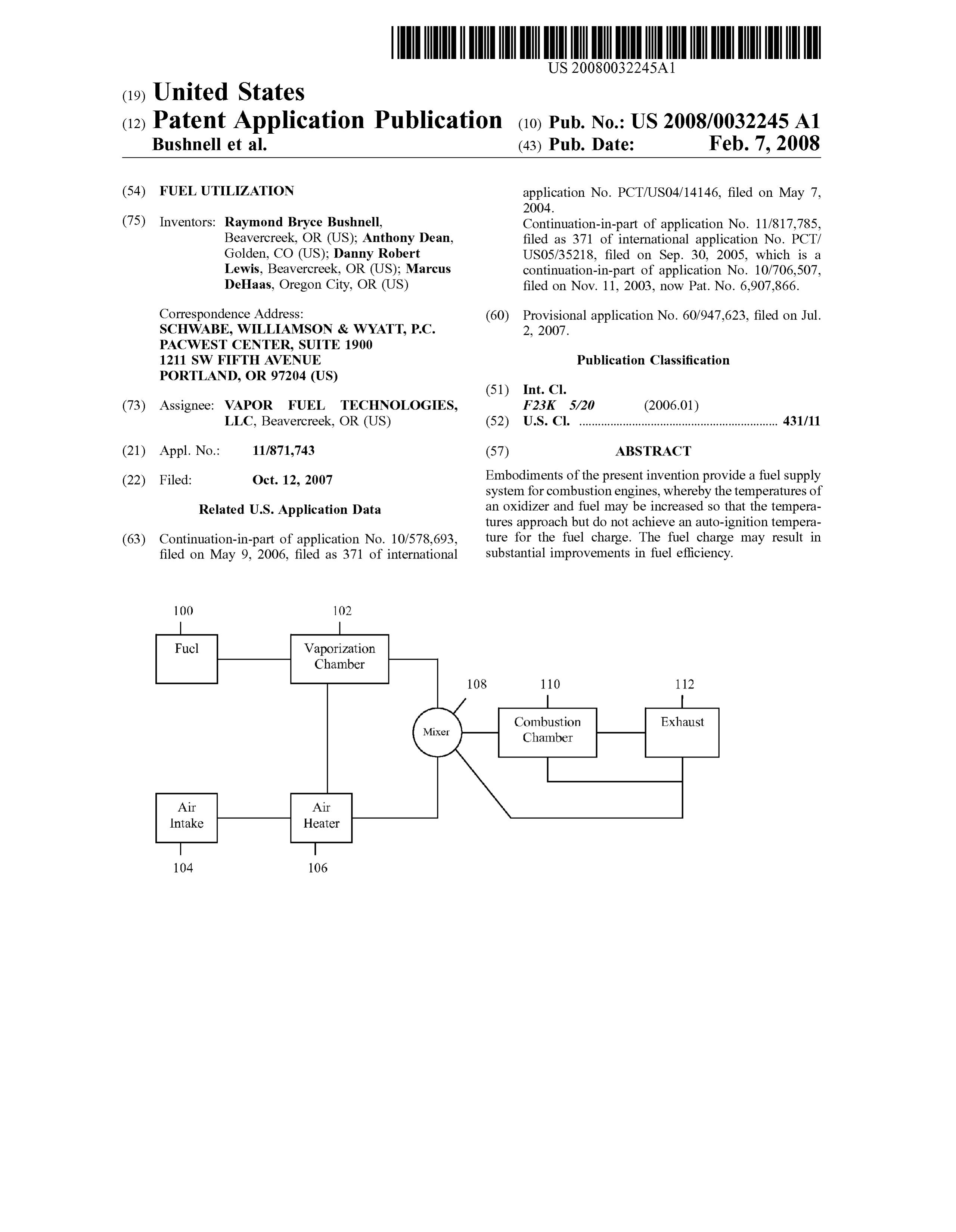
1211 SW FIFTHAVENUE Publication Classification
PORTLAND, OR 97204 (US)
(73) Assignee: VAPOR FUEL TECHNOLOGIES, F23K 5/20 (2006.01) LLC, Beavercreek, OR (US) (52) U.S. Cl. ................................................................ 431A11
(21) Appl. No.: 11/871,743 (57) ABSTRACT
(22) Filed: Oct. 12, 2007 Embodiments of the present invention provide a fuel supply system for combustion engines, whereby the temperatures of
Related U.S. Application Data an oxidizer and fuel may be increased so that the tempera tures approach but do not achieve an auto-ignition tempera (63) Continuation-in-part of application No. 10/578,693, ture for the fuel charge. The fuel charge may result in filed on May 9, 2006, filed as 371 of international Substantial improvements in fuel efficiency.
Vaporization
Chamber
Chamber
Page 2
Drawing sheet — no readable text.
Page 3
Drawing sheet — no readable text.
Page 4
Drawing sheet — no readable text.
Page 5
Drawing sheet — no readable text.
Page 6
Patent Application Publication Feb. 7, 2008 Sheet 5 of 6 US 2008/0032.245 A1 Begin
Adjust the
Temperature of the Fuel Charge
Yes
Induct Fuel Charge into Combustion Chamber
Adjust the Timing of the Combustion
Event
Initiate a
Combustion Event
Fig. 5
Page 7
Patent Application Publication Feb. 7, 2008 Sheet 6 of 6 US 2008/0032.245 A1
Induct Preheated fuel Induct Increased into Combustion amount Of Preheated Chamber fuel into Combustion
Combine Decreased
Combine EGR with
Amount of EGR with
Amount of Fuel
Fuel
Ignite Fuel Perform Spark to Ignite
Fig. 6
Page 8
US 2008/0032.245 A1 Feb. 7, 2008
FUEL UTILIZATION peratures may allow a fuel charge to prematurely ignite, for example before the piston reaches top dead center, and may
CROSS REFERENCE TO RELATED result in a decrease in efficiency and possible engine dam APPLICATIONS age. Conversely, ignition temperatures that are not elevated 0001. The present application is a non-provisional appli may contribute to an environment conducive to longer combustion durations, where components having lower igni cation of Provisional Application No. 60/947,623, filed on tion temperatures ignite first and then propagate, like a forest Jul. 2, 2007, and claims priority to said provisional appli fire, through the components requiring higher ignition tem cation. The present application is also a continuation-in-part peratures.
of Non-Provisional application Ser. No. 10/578,693, filed
May 9, 2006, and claims priority to said application. appli 0005 Additionally, various ones of these systems may cation Ser. No. 10/578,693 is the U.S. National Entry of a also require Substantially steady state conditions to function PCT that claims priority to now issued U.S. Pat. No. efficiently. For example, in an HCCI mode, there is no 6,907.866, having a filing date of Nov. 11, 2003. The present sparking device to trigger the combustion event. Rather, application is also a continuation-in-part of application Ser. combustion is dependent solely upon the conditions within No. 1 1/817,785, filed Sep. 4, 2007, and claims priority to the cylinder, i.e., temperature, pressure, air-to-fuel ratio said application. application Ser. No. 1 1/817,785 is the U.S. (“AFR), fuel state, and exhaust gas recirculation (“EGR). National Entry of a PCT application that claims priority to These conditions are typically varied to control when auto now issued U.S. Pat. No. 7,028,675, with a filing date of ignition, and consequently, combustion occurs. If there is a Mar. 4, 2005, which is a continuation-in-part of now issued rapid change in any one of these conditions, for example U.S. Pat. No. 6,907.866, having a filing date of Nov. 11, during periods of rapidly increasing loads, then the com 2003. bustion event becomes unpredictable. As an example, when an engine increases its revolutions per minute (“RPMs)
TECHNICAL FIELD there is less time for the fuel charge to change States within the cylinder. This effectively reduces the likelihood of 0002 Embodiments of the present invention relate to the matching the density of the fuel with the density of the field of providing vaporized or liquid fuel to engines, and induced air, thereby resulting in an AFR mismatch. This more particularly to vapor and liquid fuel systems where density mismatch may lead to premature ignition, possible various parameters of the fuel mixture may be varied to engine damage, and unacceptable emissions. increase the efficiency of a given fuel charge.
0006. Applicants have developed techniques to improve
BACKGROUND AND BRIEF DESCRIPTION combustion Such that fuel economy may be improved in both vapor and liquid charged systems. In various embodi 0003 Vaporizing fuel prior to its entrance into the cyl ments, the fuel (liquid or vapor) and air may be indepen inder can lead to improved performance, particularly with dently heated and the densities of each controlled. Upon respect to Substantially improved fuel economy. Applicants mixing the air and fuel, an air to fuel ratio of 14.7-1 may be have discussed the advantages and various inventions Sur maintained at elevated temperatures prior to entrance into a rounding vapor fuel systems in many of their current patents combustion chamber or within the combustion chamber. In and pending applications (See, U.S. Pat. Nos. 6,681,749; various embodiments, elevating the pre-combustion tem 6,907,866; 6.966,308; 7,028,675; and application Ser. Nos. perature so that it approaches, but does not achieve, an 1 1/465,792 and 11/421,698). While some of these patents auto-ignition temperature for a given fuel charge may result and applications teach advantages of running an engine in more efficient combustion and a system that is better able “lean' (i.e., at an air to fuel ratio of greater than about 15 to to handle transitions. Such may be attributable to several 1), they also teach improving fuel economy in conventional factors including the homogeneity of the fuel charge, systems that are designed to operate at current Stoichiomet increased flame speed, increased in cylinder temperature, ric conditions, such as an air to fuel ratio around 14.7 to 1. and/or the multiple flame fronts encountered. In further 0004 More recently, systems have been focused on embodiments, fuel economy may be improved by altering increasing the temperature of a fuel charge once it enters the various other parameters which allow for better control of combustion chamber to a point where the mixture of air and the combustion of the fuel charge. Such parameters may fuel spontaneously ignite. The low end temperature at which improve efficiency by also increasing the flame speed and typical grade gasoline begins to ignite, in Such a manner, is decreasing the combustion duration. around 500 F. Most systems are achieving this necessary temperature through increased compression ratios. BRIEF DESCRIPTION OF THE DRAWINGS Examples of Such systems include Controlled Auto Ignition
(CAI) and Homogeneous Charge Combustion Ignition 0007 Embodiments of the present invention will be (HCCI). These systems have disadvantages and are not well readily understood by the following detailed description in Suited for dealing with transients, such as periods of accel conjunction with the accompanying drawings. Embodi eration or deceleration. One of the disadvantages that may ments of the invention are illustrated by way of example and stem from the wide ranges and diversity of temperatures not by way of limitation in the figures of the accompanying required for the spontaneous ignition of a given fuel charge drawings.
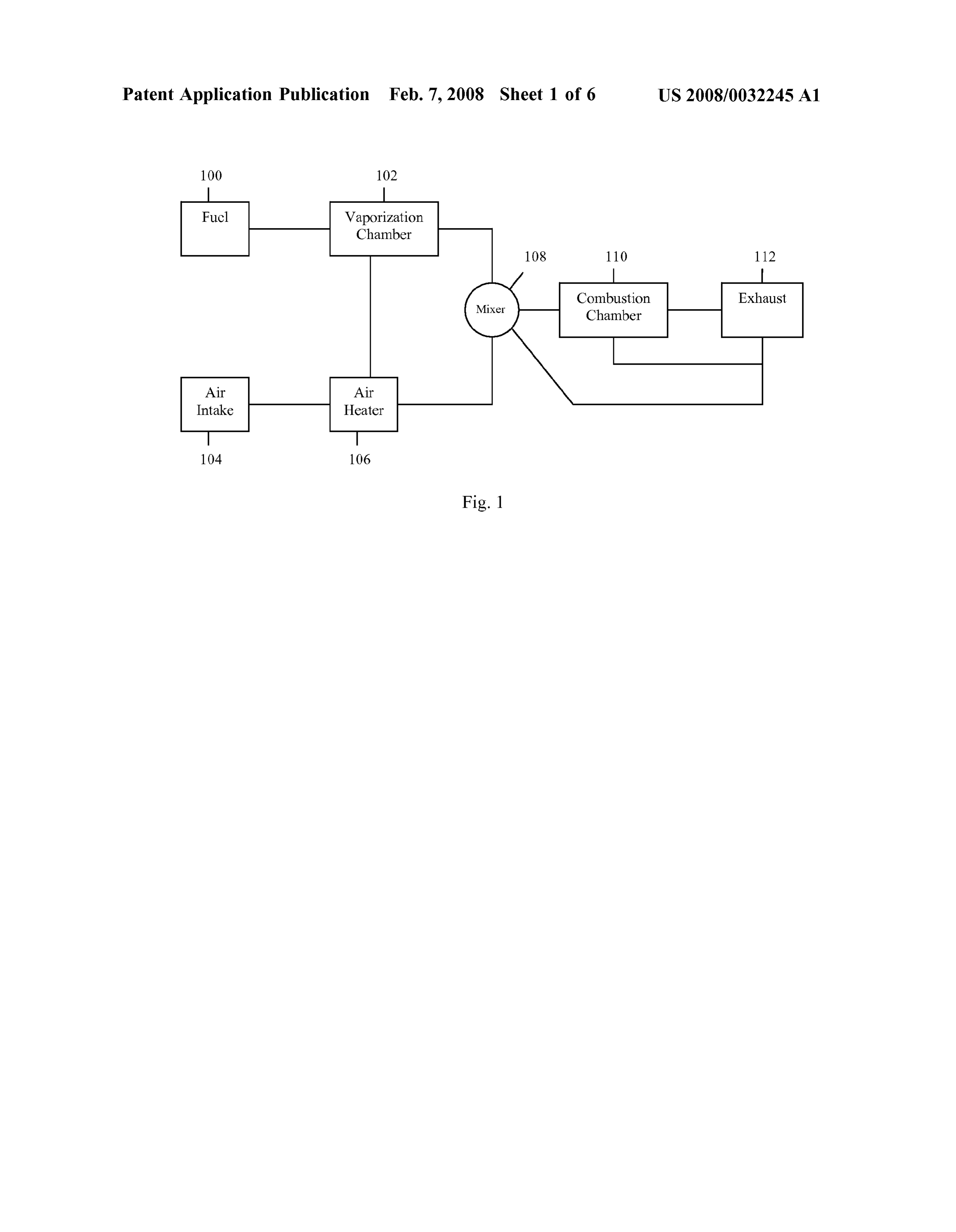
(e.g. 500°-1100°F). For example, these systems attempt to 0008 FIG. 1 illustrates a block diagram in accordance ignite the entire charge at one moment in time. Because of with various embodiments of the present invention; this, their temperatures are generally elevated towards the higher end of the temperature range. This wide range of 0009 FIG. 2 illustrates a graphical representation of a ignition temperatures combined with elevated ignition tem relationship between diluting an amount of fuel and the need
Page 9
US 2008/0032.245 A1 Feb. 7, 2008
for improved combustion in accordance with various Furthermore, the terms “comprising.”“including.”“having.”
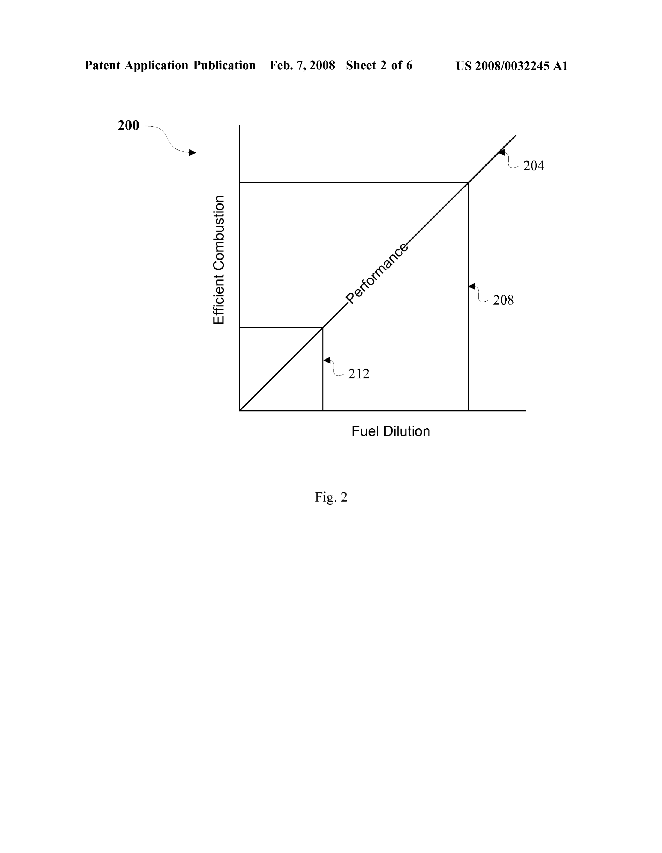
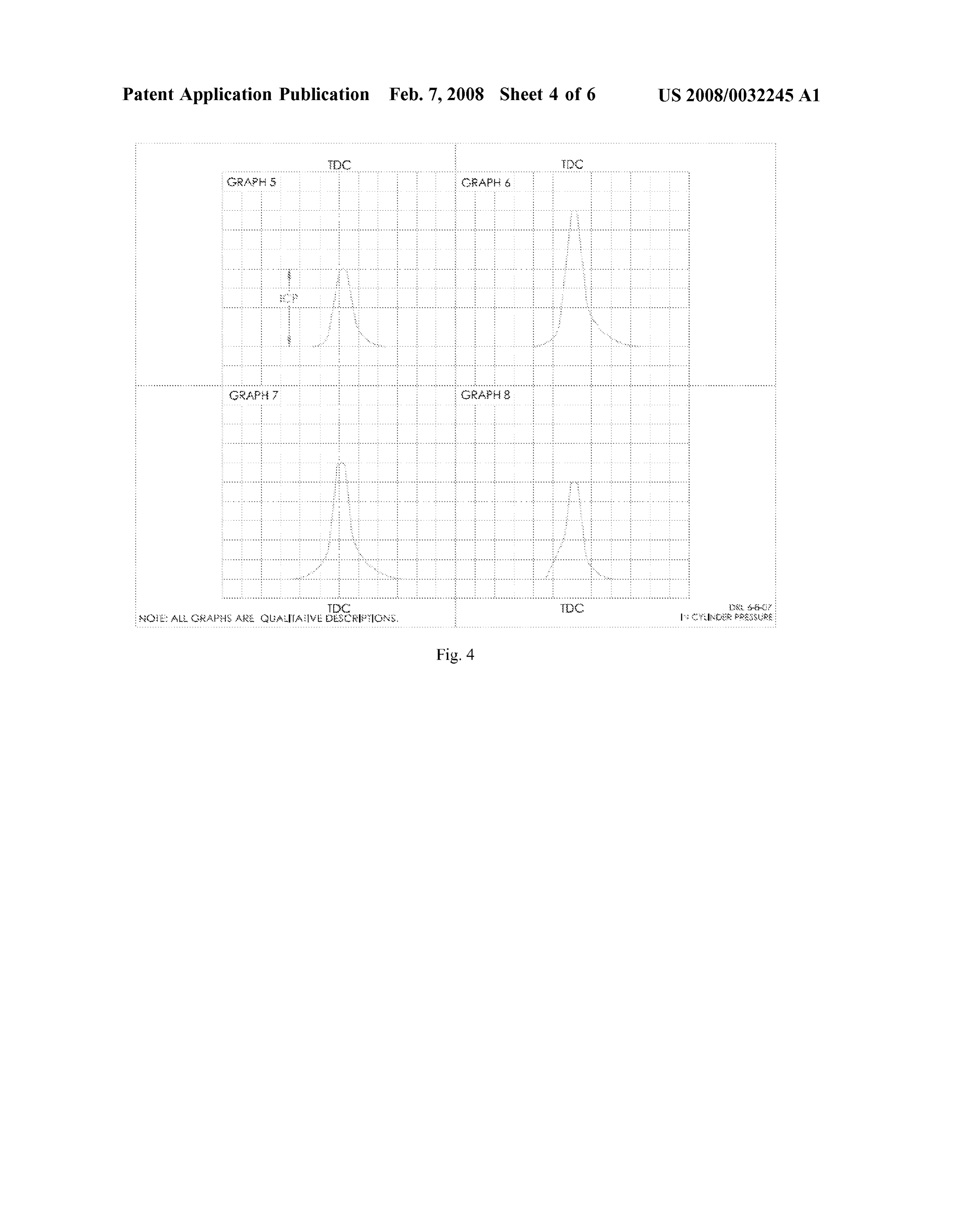
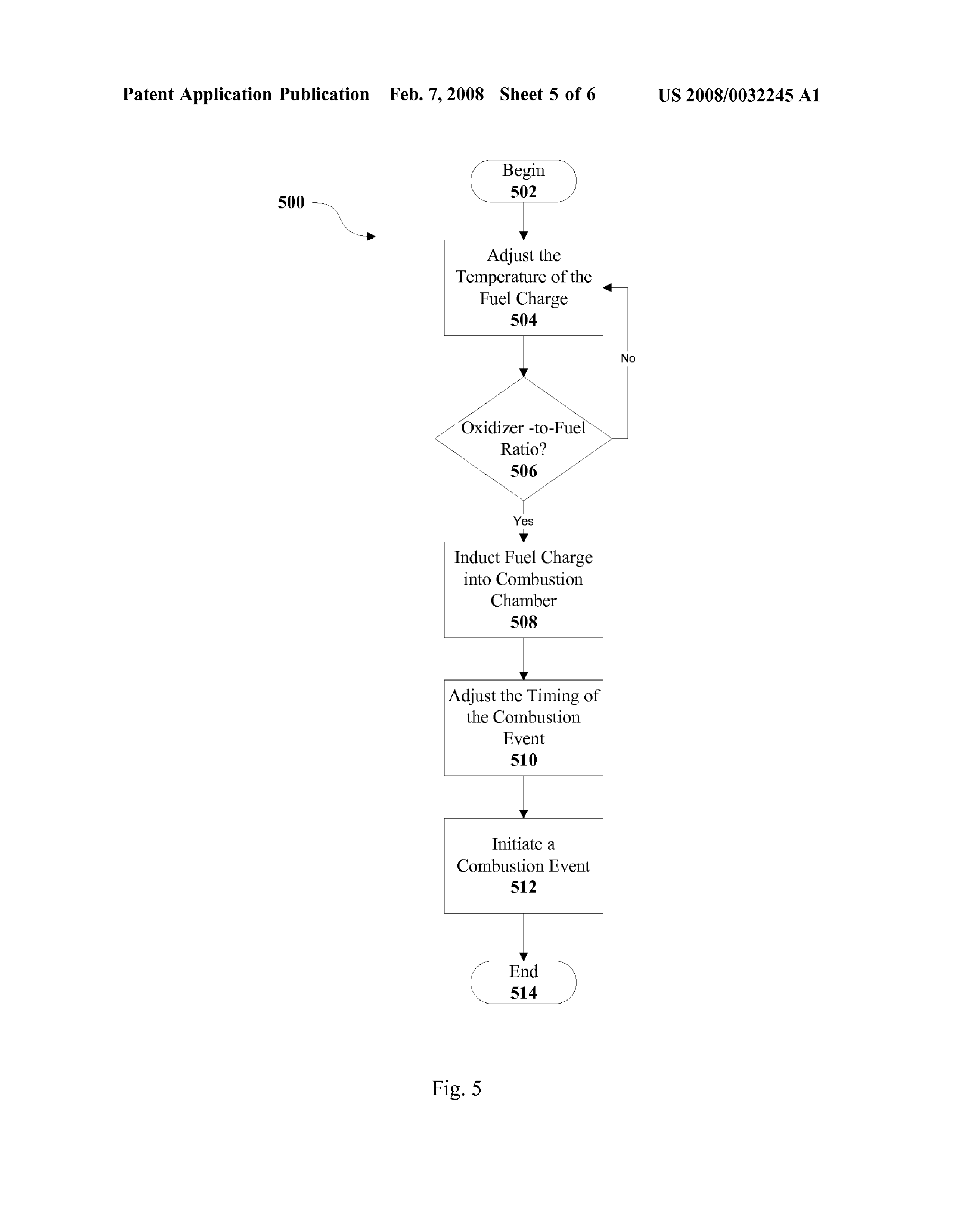
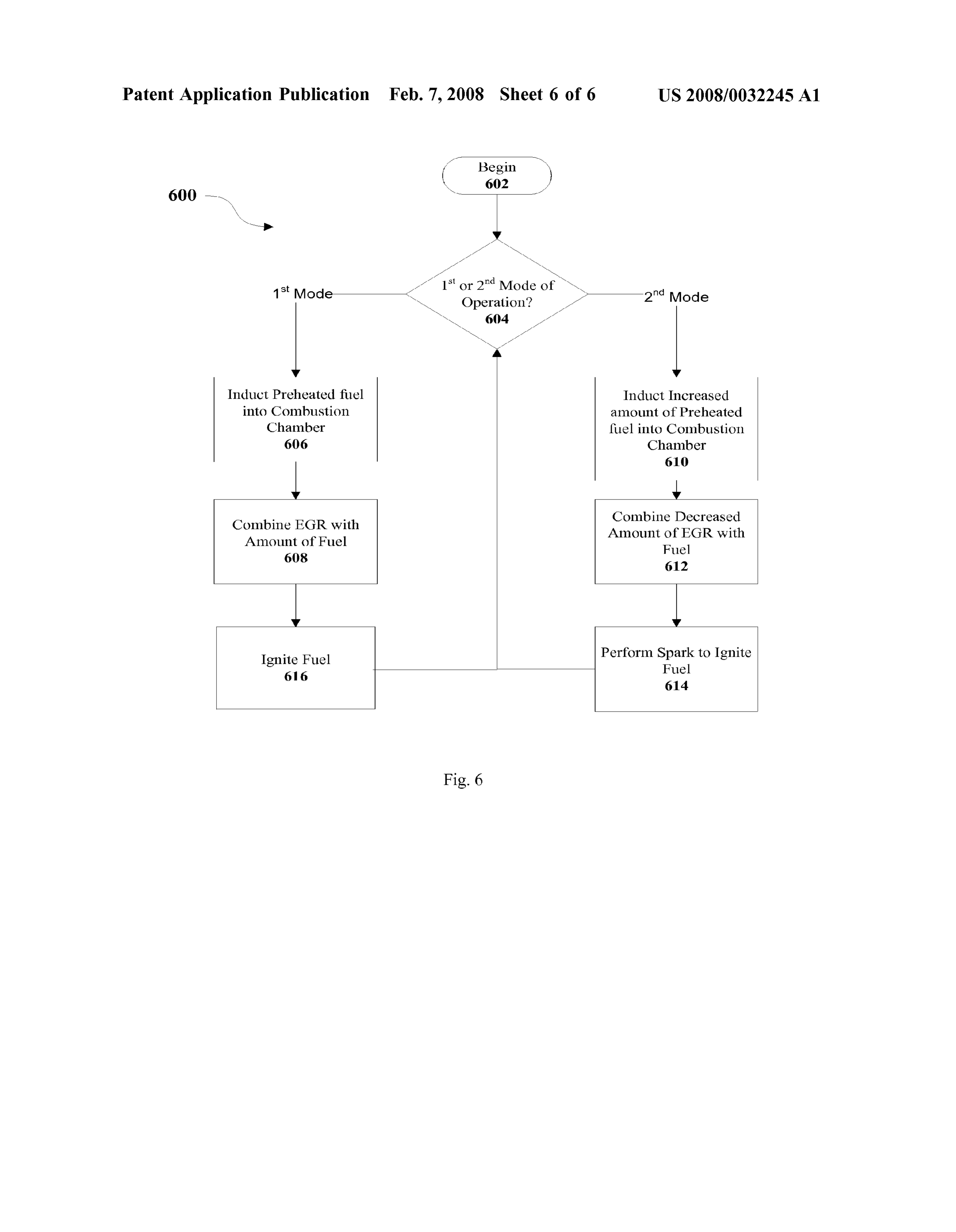
embodiments of the present invention; and the like, as used with respect to embodiments of the 0010 FIG. 3 illustrates graphical representations of the present invention, are synonymous. various combustion durations with respect to top dead center 0020. In various embodiments, fuel efficiency may be of various combustion events; improved by causing the fuel charge to be more homoge 0011 FIG. 4 illustrates graphical representations of the neous in nature, i.e., the vapor makeup of a given charge has in-cylinder pressures (“ICP) of the various combustion a higher concentration of like components, and correspond events illustrated in FIG. 3, respectively; ingly, more similar ignition temperatures. It has been found that as the fuel vapors become more homogeneous in nature 0012 FIG. 5 illustrates a flow diagram depicting a com their combustion duration becomes more uniform and, con bustion operation in accordance with various embodiments sequently, it becomes easier to find and maintain an optimal of the present invention; and temperature for increasing the overall efficiency of the 0013 FIG. 6 illustrates a flow diagram depicting a com system. Increasing the temperature of the fuel charge to the bustion operation in accordance with various embodiments optimal temperature may, for instance, increase the effective flame speed. By optimizing the temperature of a fuel charge of the present invention. and the timing of a spark assist to initiate ignition of a
DETAILED DESCRIPTION OF EMBODIMENTS
particular fuel charge, the combustion duration may be more
OF THE INVENTION
efficient, i.e., a shorter and more uniform combustion dura tion closer to TDC and at a more optimal crank angle. In 0014. In the following detailed description, reference is various embodiments a variety of fuels may be utilized, made to the accompanying drawings which form a part including but not limited to, ethanol based fuels, fossil fuels hereof, and in which are shown by way of illustration including their derivatives, and hybrid fuels. The invention embodiments in which the invention may be practiced. It is is not to be limited in this regard. to be understood that other embodiments may be utilized 0021. In various embodiments, efficiency may be and structural or logical changes may be made without improved for fuel charges having a range of ignition tem departing from the scope of the present invention. Therefore, peratures by initiating a chain reaction within the combus the following detailed description is not to be taken in a tion cylinder. For example, given a fuel charge having a limiting sense, and the scope of embodiments in accordance range of components, combustion may be initiated via a with the present invention is defined by the appended claims spark which ignites a portion of the fuel charge and creates and their equivalents. a flame front. The flame front and combustion of a portion 0.015 Various operations may be described as multiple of the fuel charge may increase the temperature and pressure discrete operations in turn, in a manner that may be helpful inside the combustion chamber causing components having in understanding embodiments of the present invention; lower ignition temperatures to auto-ignite. This auto-igni however, the order of description should not be construed to tion may create more flame fronts and consequently further imply that these operations are order dependent. increase the temperature and pressure within the cylinder. The further increases of temperature and pressure may then 0016. The description may use perspective-based ignite the components having higher ignition temperatures. descriptions such as up/down, back/front, and top/bottom. This chain reaction may continue until Substantially all of Such descriptions are merely used to facilitate the discussion the charge has been cooperatively combusted. In various and are not intended to restrict the application of embodi embodiments, as the fuel charge becomes more homoge ments of the present invention. neous the number of steps in the chain reaction may decrease 0017. The terms “coupled and “connected,” along with and resultantly may decrease the combustion duration, their derivatives, may be used. It should be understood that which in turn may allow better optimization of the timing these terms are not intended as synonyms for each other. and other parameters. In various other embodiments, such a Rather, in particular embodiments, “connected may be used chain reaction may be instigated without the use of a spark, to indicate that two or more elements are in direct physical for instance by inducting EGR into the combustion cylinder. or electrical contact with each other. “Coupled may mean 0022 Combustion duration generally refers to the period that two or more elements are in direct physical or electrical of time it takes for a given fuel charge to combust. Alter contact. However, “coupled may also mean that two or natively, and for the purpose of this explanation, flame speed more elements are not in direct contact with each other, but generally refers to the rate at which the fuel is burned. yet still cooperate or interact with each other. Theoretically, for maximum efficiency, all of the fuel would 0018 For the purposes of the description, a phrase in the burn at exactly the same moment. For example, if the entire form "A/B means A or B. For the purposes of the descrip fuel charge had a spontaneous ignition temperature of 500 tion, a phrase in the form “A and/or B' means “(A), (B), or F., when that temperature is reached in the combustion (A and B). For the purposes of the description, a phrase in chamber all of the fuel would substantially instantaneously the form “at least one of A, B, and C’ means “(A), (B), (C), ignite thereby transferring the maximum amount of energy (A and B), (A and C), (B and C), or (A, B and C). For the possible for that given fuel charge. This, however, is not purposes of the description, a phrase in the form “(A)B' realistic as fuel contains various components which neces means “(B) or (AB) that is, A is an optional element. sitate different ignition temperatures, and consequently, ignition at different times, i.e., a longer combustion duration.
0019. The description may use the phrases “in an For instance, in current systems, the various components in embodiment,” or “in embodiments,” which may each refer a charge vary greatly which can cause the ignition tempera to one or more of the same or different embodiments. ture of such a charge to vary, often times, by several hundred
Page 10
US 2008/0032.245 A1 Feb. 7, 2008
degrees. Thus to burn a charge having Such greatly varied example, oxygen, temperature, hydrocarbons, and/or vapor ignition temperatures, more flame fronts are encountered density. Through this monitoring, the sensors may control and a significant amount of energy is expended over a longer the heating and/or mixing events, for both the oxidizer and period of time which in turn decreases fuel efficiency. In the fuel vapors, to maintain a 14.7 to 1 AFR. By maintaining various embodiments, improving the homogeneity of the this ratio, the quantity of the fuel charge may be varied, i.e., feed stream Such that there is a significantly reduced range diluted relative to the cylinder volume, to achieve efficiency of ignition temperatures within a given fuel charge, thereby as well as allowing for adjustments to constantly changing reducing flame fronts and allowing for a more optimal combustion strength. In various embodiments, sensors may temperature and timing, Substantially improves fuel effi also or alternatively be employed downstream from the ciency. combustion event, and adjustments may be made based on emissions content.
0023. In various embodiments, the vapor and/or liquid fuel, prior to being mixed with air or another oxidizer, may 0026. In various other embodiments, it has also been be separated into generally like components so that the fuel found that increasing the temperature of both the fuel and the charge is more homogeneous. Such homogeneity can oxidizer may generate additional benefits for combustion improve the combustion duration in the situations where the engines. Applicants have discovered that as the vaporized temperature is below or at the temperature required for auto fuel that is being conveyed to the engine's combustion ignition of the similar components in the combustion cham chamber is mixed with air, condensation may appear. This ber. In various embodiments, liquid fuel may be viewed as can happen, for example, as a result of the air having a being comprised of fractions that may vaporize at different temperature below that of the liquid fuel vaporization tem temperatures. This vaporization can be achieved, for perature. As the air is mixed with the fuel vapors to achieve example, by initial heating of liquid fuel at a first tempera the desired air-to-fuel ratio, the cooler temperature of the air ture (e.g. 70° F.) and Subsequently increasing the tempera reduces the temperature of the vaporized fuel and returns it ture as the differing fractions of the liquid fuel are vaporized to liquid form, i.e., it condenses. This condensation may and/or decreased vaporization of the fuel is detected. alter the combustion characteristics and/or homogeneity of Referred to herein as fractionation, applicants have learned the fuel charge, thus decreasing efficiency and/or flame that generally sequentially supplying fractions of vapors to speed. Accordingly, in various embodiments, the tempera the combustion chamber will improve efficiency by allowing ture of the air, vapor, and/or the mixture may be elevated to a more predictable and uniform combustion duration which a point above that required for vaporization so the fuels will may be adjustably triggered to maximize the energy transfer. remain in vaporized form, homogenously mixed to a desired ratio, and Substantially devoid of condensation. Such heat 0024. Though not essential, in various embodiments, treatment, i.e., the creation of a higher temperature, vapor?air fractionation may help to decrease the combustion duration mixture may help achieve improved performance. by reducing the variation of ignition temperatures within a fuel charge. For example, while various standard ignition 0027) Further such heating of the air supply, vaporized engines may utilize a fuel charge having ignition tempera fuel, and/or air-vaporized fuel mixture may also further tures which may vary between 500°-1100°F., fractionation enhance the flame speed of the fuel/air mixture and shorten may produce a first fraction of vapor in which the ignition the combustion duration. This in turn can extend the “lean temperatures may vary between approximately 500 F-700 limit” (i.e., the highest air-to-fuel ratio where the engine can F., and a second fraction in which the ignition temperatures perform satisfactorily, without excessive loss of power, may vary between approximately 700°-1100°F. In various misfire, and/or unacceptable hydrocarbon emissions). This embodiments, the more homogeneous bands may be nar extension of the lean limit may have several advantages, rower or wider. Therefore, when the fuel charge is ignited, including, but not limited to: (1) improving fuel economy the “forest fire' effect mentioned earlier may be reduced, and (2) decreasing the amount of NOx produced. This i.e., the combustion duration is decreased. With the com pre-heating may also help to achieve Some of the benefits bustion duration decreased, in various embodiments, the that improve engine performance, including not only pre timing of the spark may be adjusted to place the shortened venting condensing of the fuel, but also increasing the flame combustion duration substantially just past TDC. This also speed.
improves thermal efficiency of the system, as the thermal 0028. In various embodiments, the Exhaust Gas Recir losses associated with combustion across different ignition culation (“EGR) amount may be increased, which in turn temperatures (which occur in Systems having wide ranging may increase efficiency and fuel economy. EGR, effectively, spontaneous ignition temperatures (e.g. from 500' F., to recirculates a portion of the engine's exhaust (which can be 1100 F)), are reduced. over 1000 F) back to the engine cylinders. Mixing the 0.025 Heating the fuel and vapor, however, may alter the incoming fuel charge with EGR serves to help raise the density of the fuel vapors. Therefore, to maintain a balance temperature of the charge in the combustion chamber to the oxidizer may also be heated to alter its density. The thereby increase the flame speed and decrease the combus tion duration. It also fills the volume of the chamber with heating of the oxidizer may, in various embodiments, work inert gases, mostly nitrogen, carbon dioxide, and steam to maintain an AFR that is compliant with emissions stan which not only reduces the amount of fuel charge used while dards and/or maintain currently accepted AFR. This AFR, in being diluted to match the load requirements, but it allows various embodiments, may be controlled during operation the air to fuel mixture to remain at a desired stoichiometric by a density balance control strategy and implemented by a controller. In various embodiments, the density balance ratio (e.g. about 14.7 to 1). In one embodiment, the EGR control strategy may control the varying densities of both the may be between 15% and 30%.
oxidizer and the fuel vapors by the use of sensors upstream 0029. In another embodiment, the temperature of the fuel from the combustion event. These sensors may monitor, for charge may be raised or lowered by varying both the
Page 11
US 2008/0032.245 A1 Feb. 7, 2008
temperature of the oxidizer mixed with the fuel and/or the 0033. In an example embodiment, it may be known that amount of EGR allowed into the combustion chamber. In vaporizing fuel at 70° F. generates a more homogeneous effect, the diluted density due to the increase in temperature vapor which may substantially spontaneously ignite within of the fuel charge may act as the coarse adjustment to enable a known band of temperatures (e.g. 500 F-78.8°F). Con a faster flame speed, while the EGR makes finer adjustments sequently, a vapor fuel system in accordance with various that may react to quick changes in conditions. embodiments may vaporize a first fraction of gas and adjust the operating conditions to heat the vapor and/or an oxidizer 0030 These temperatures, in another embodiment, may so that the mixture is in a ratio of 14.7-1 and approaches a allow for increased efficiency when acceleration is needed, temperature of 450° F., a temperature which approaches but and consequently, the spark plugs (or other ignition source) does not achieve spontaneous ignition. Accordingly, in vari may be employed to initiate ignition. In one embodiment, ous embodiments, an internal combustion engine having a the temperature of the fuel vapor may be increased to a combustion chamber may then induct the homogenous fuel temperature just below that which is required to spontane charge (e.g. fractionized fuel vapors) into the combustion ously ignite the fuel charge, a spark plug may then initiate chamber. Thereafter a spark from a spark plug may be used ignition of the fuel charge just prior to or at TDC, and thus to initiate ignition of the fuel charge. In such an instance, the create the necessary increased pressure and temperature to rate at which the entire fuel charge is expended may be Substantially auto-ignite the fuel charge. The increased tem substantially increased thereby increasing the overall effi perature of the fuel charge combined with the generally ciency of the engine. As the combustion duration continually homogeneous nature of the fuel charge, in accordance with decreases, the timing may be changed to position the com various embodiments, may lead to a faster flame speed, bustion closer to TDC in order to maximize the energy shorter combustion duration, increased efficiency, and better transfer.
control. 0034. In various embodiments, as thermal efficiency 0031. In various other embodiments, the fractionation increases, the pressure due to combustion will increase discussed above may apply to liquid fuel injected systems, while the duration of the combustion event will decrease. As in that the homogeneity of the fuel charge may improve the combustion duration decreases, the ignition timing may efficiency. In one example embodiment, the liquid fuel may be adjusted to move ignition closer toward TDC, and when be vaporized, or separated by other methods, and condensed the fastest flame speed and shortest combustion duration is such that the fuel is not thoroughly mixed, but rather reached (e.g. at or near auto ignition), ignition may occur at separated by generally like components having similar or close to TDC. In various embodiments, a sensor or vaporization, auto ignition, condensation temperatures, and/ sensors and logic may recognize the increased pressure and, or flame speeds. Such fractions may then be injected into the in addition to the aforementioned timing change, increase combustion chamber for combustion. The homogeneity of the amount of EGR so the combustion pressure can match fuel charge allows the temperature of the fuel charge to be the power that would be produced by a normal combustion. increased so that it approaches, but does not achieve, a The additional EGR will act as filler and substantially dilute Substantially similar auto-ignition temperature for the entire the quantity of fuel and air within the cylinder thereby fuel charge prior to a spark. Consequently, when the spark reducing the quantity of fuel consumed, thus improving is initiated, the decreased combustion duration is allowed to efficiency while matching the power consumed by standard transfer more energy closer to TDC, thereby allowing for methods. Moving the ignition timing to a point closer to improved efficiency. TDC and diluting the fuel and air quantity by heating the charge, which thus changes the density, and adding EGR are 0032. Additionally, it has been observed that standard critical elements to matching the power requirement, pro onboard computer systems may further enhance the benefits tecting the engine and improving fuel economy. discussed above. For example, in standard onboard com 0035) Reference is made to FIG. 1, which provides a puter systems, upon periods of acceleration the amount of block diagram of the components of a system in accordance EGR is decreased while the timing of the spark plug is with embodiments of the present invention. A combustion advanced. In one embodiment, the reduction of EGR neces chamber 110 may be coupled to a mixer 108 which com sitates that more fuel be added to the cylinder, therefore bines heated air from air intake 104 and air heater 106 with allowing for acceleration. Additionally, the advanced igni vaporized and/or fractionated fuel from fuel tank 100 and tion timing causes the spark to occur Sooner in the com vaporization chamber 102. Additionally, in various embodi pression cycle, which may be prior to the fuel charge ments an exhaust system 112 may be coupled to the com meeting the required ignition temperature and spontane bustion chamber 110 and/or a mixer 108. The exhaust ously combusting. Therefore, in various embodiments, the system 112 allows for recirculation of exhaust, i.e., Exhaust reduced EGR and the advanced ignition timing may have the Gas Recirculation (“EGR). In various embodiments effect of decreasing the temperature of the fuel charge and exhaust system 112 may be coupled, directly or indirectly, to returning the engine to a standard spark initiated ignition other components. The invention is not to be limited in this mode. This would not be possible if the fuel charge operated regard.
at the increased temperatures required for auto-ignition, as is done in current systems (e.g. HCCI). In fact, it might lead to 0036). In various embodiments, the air (or other oxidizer) premature ignition of the fuel charge, and consequently, mixed with the fuel vapor may be heated by a dedicated heat damage to the engine. Furthermore, even in a standard Source (e.g. heating coils disposed within the air flow) or via ignition mode, a fuel mixture having a decreased but higher passive heating from engine or other vehicle components. than ambient temperature may still have the effect of Further, the air may be heated (e.g. by the engine) prior to decreasing the combustion duration in comparison to non air intake 104. In one embodiment a heat source 106 may vaporized and/or non pre-heated fuel. control the temperature of the air flow and elevate the
Page 12
US 2008/0032.245 A1 Feb. 7, 2008
temperature of the air Supply as deemed necessary based on other embodiments, the adjustment of the spark may be the content of the emissions and/or vaporization temperature based on at least the characteristics of the fuel charge/fuel of the fractionated fuel vapors. In various embodiments, the vapors.
air inflow may be controllably elevated in temperature from, 0040. After combustion, the exhaust may then be trans for example, a range of about 60°F. to 80° F. to a tempera ferred to an exhaust system 112. The exhaust system, in ture of about 100° F. to 120° F., or higher. Again, the various embodiments, may dispose of the exhaust or recir temperature of the air Supply may vary depending on the emission content and/or the temperature required for vapor culate the exhaust gas back to the combustion chamber 110 izing and mixing with the instant fraction of fuel, and may or the air vapor mixture that is to be combusted. In one be controlled based thereon. In various embodiments, the air embodiment, Exhaust Gas Recirculation (“EGR) may be and/or oxidizer may be controllably heated in order to used to improve efficiency and fuel economy. In various maintain a desired oxidizer-to-fuel ratio. In various other other embodiments, the amount of EGR that is circulated embodiments, the intake air need not be heated. may be determined and controlled by onboard computers and a series of valves (not shown). The optimal percentage 0037. In various embodiments, the liquid fuel in fuel tank of EGR varies and is limited by the fuel characteristics such 100 may be vaporized in vaporization chamber 102. The as the fuel charge's auto-ignition temperature, and the vaporization chamber 102 may include a number of heating amount of fuel required for various load conditions. Addi sources (not shown) to controllably heat the liquid fuel tionally, in other embodiments, the EGR may be circulated including but not limited to engine component proximity, to the mixer 108 to increase the temperature of the fuel engine fluids, electrical circuits, independent heating and/or oxidizer prior to the fuel charge entering the com devices, and/or heated air from intake 104 or air heater 106. bustion chamber 110.
In various embodiments, the vaporization chamber 102 may 0041. In various embodiments, one or more sensors may vaporize the fuel by fractionation, i.e., heating the fuel in be disposed in the feed stream for the combustion chamber increments so as to improve the homogeneous nature of the 110, and adapted to sense a characteristic of the fuel charge, fuel vapors. More specifically, in one embodiment, fuel may Such as hydrocarbon content, temperature, density, ignition be transferred from fuel tank 100 to vaporization chamber temperature, air to fuel ratio, etc. The sensors may be 102. The fuel may occupy the lower half of the tank, and a coupled to an onboard computer, which may in turn adjust heating element and temperature sensor (not shown) may be various parameters to improve the combustion of the par set to incrementally increase the temperature settings for ticular charge. For example, if the amount of hydrocarbons heating the fuel in the vaporization chamber 102 thereby in the sensed fuel charge is out of balance, which could causing fractionation of the fuel. As mentioned previously, result in an incorrect ignition, the amount of EGR may be the fractionized fuel is more homogeneous in nature which increased or decreased, the timing may be advanced or improves the combustion duration, and consequently, effi retarded, and/or the temperature of the fuel charge may be ciency. In various embodiments, a sensor may monitor otherwise increased or decreased. In another example, the various characteristics of the created vapor, and control the density or the temperature of the charge could be sensed and further vaporization of the fuel to maintain a desired mixture corrected as desired in order to achieve more optimal density and/or homogeneity range. combustion at normal Stoichiometric conditions. 0038. In one embodiment, the air heater 106 may be 0042 FIG. 2 is a graph illustrating a relationship between coupled to the vaporization chamber 102 to facilitate con diluting an amount of fuel to be combusted in a cylinder and veyance of the fuel vapors to the mixing chamber 108 and the need for more efficient combustion of the fuel to main subsequently to the combustion chamber 110. While the tain an acceptable level of performance. In various embodi air-fuel mixture is being conveyed, however, as previously ments this may be achieved by adjusting the combustion of discussed, there may be the possibility that a part of the the diluted fuel charge based on various characteristics of the mixture may condense to liquid form prior to entering the fuel charge.
mixing chamber 108 and/or the combustion chamber 110. In one embodiment, to prevent condensation from taking place, 0043. In various embodiments, dilution of a fuel charge the air heater 106 may establish a temperature of the air at may result from vaporizing an amount of fuel and/or mixing or above the temperature of the of the fractionated fuel the fuel with a heated oxidizer. For example, as an amount vapors. In another embodiment, the fuel vapors carried by of fuel changes phase from a liquid to a gas its density will the heated air to the mixer 108 may be heated again to a be reduced. Mixing the fuel with a heated oxidizer may also temperature above that which the fractionated fuel was or additionally reduce the fuel's density. In various embodi vaporized. This may help to improve burning efficiency as ments, the fuel and/or oxidizer may be diluted in order to well as prevent condensation in the mixing chamber itself. maintain a desired oxidizer-to-fuel ratio, such as for In various embodiments the mixer 108 may combine the example, about 14.7-to-1. This may allow for the optimiza heated intake air and the heated fractionated fuel to form a tion of power and fuel economy while avoiding known NOX fuel charge. This mixture may be controlled, by a controller issues if a standard catalytic converter is used. With the fuel (not shown), in order to maintain a desired oxidizer-to-fuel and/or oxidizer having reduced densities, due to their ratio. increased temperatures, the result may be less fuel and oxidizer, by weight, required to fill the combustion cylinder.
0039. In one embodiment, after the fuel vapors and/or In this manner, less fuel may be consumed thereby increas fuel charge have been passed to the combustion chamber ing efficiency.
110, a spark plug (not shown) may perform a spark to
Substantially ignite the fuel charge. The timing of the spark 0044) In various embodiments, another effect of the may be adjusted, by a controller, so combustion of a fuel increased temperatures of the fuel and/or oxidizer may be a charge may occur after and/or at an optimal crank angle. In shorter and more efficient combustion duration. Improved
Page 13
US 2008/0032.245 A1 Feb. 7, 2008
combustion duration may allow a diluted fuel charge to 0050 Graphs 3 and 4 illustrate a spark assisted auto provide acceptable levels of performance by combusting the ignition as discussed above with reference to various diluted fuel at an optimized crank angle (e.g. 3 to 15 degrees embodiments. In the graphs, the conditions within the cyl past TDC). In this manner, increasing the temperature of the inder are very close to those needed to Support auto-ignition fuel and/or oxidizer may not only serve to dilute the fuel when the spark plug ignites prior to TDC. In graph 3, the charge, but also provide a mechanism for increasing the resulting flame front quickly raises the temperature and efficiency of a combustion event to maintain an acceptable pressure to a point where the remaining fuel Substantially performance level. As previously mentioned, in various auto-ignites. In graph 4 the combustion event requires more other embodiments, EGR may also be used to dilute and fuel be burned as a result of the flame in order to achieve the increase the temperature of a fuel charge. conditions required to support auto-ignition, increased pres 0045. As shown in FIG. 2, a performance line 204 is Sure and temperature. Graph 4 is therefore, not as efficient as illustrated. This may represent an acceptable level of per graph 3. This becomes apparent when comparing the ICPs, formance for a given fuel charge. At line 212, a fuel charge graphs 8 and 7. Because the combustion duration of graph may be diluted by any of the methods previously discussed. 4 is slightly longer than that of graph 3, the ICP of graph 8 At line 212, because the fuel charge has been diluted, there is slightly less than that of graph 7, and consequently, is a need for increased efficient combustion of the fuel slightly less efficient. While graph 8 is slightly less efficient charge to produce the desired amount of performance. than graph 7, it can be seen that both Graphs 8 and 7 have Similarly, at line 208 a fuel charge is represented as being ICPs greater than that of graph 5, the slow flame propagation event.
further diluted with respect to line 212. Therefore, to main tain the same level of performance with respect to line 212, 0051) The increases of ICP in graphs 6, 7, and 8, relative a further increase in temperature and/or efficient combustion to graph 5, illustrate an increase in efficiency that may be may also be needed. Consequently, FIG. 2 illustrates that as possible. More specifically, in graphs 6, 7, and 8, the fuel a fuel charge becomes further diluted, there is a need for a may be diluted to match the ICP of graph 5. This translates more efficient combustion of the diluted fuel charge to into less fuel accomplishing the same amount of work as the maintain a desired level of performance. As illustrated, line typical flame propagation event.
208 produces the same performance with less fuel being utilized. This relationship is more fully described with 0052 These graphs are not intended to be exact illustra reference to FIGS. 3 and 4. tions of the occurrences but rather a general illustration of the effect of various combustion durations/flame speeds.
0046. It should be understood that FIG. 2 is provided only for the purpose of demonstrating a general relationship 0053) Referring now to FIG. 5, a flow diagram of a between fuel dilution and a need for efficient combustion of combustion operation 500 is illustrated in accordance with the diluted fuel. FIG. 2 is not intended to be an exact various embodiments of the present invention. The opera representation of the illustrated relationship as those of skill tion may begin at block 502, and progress to block 504 in the art will readily recognize. It is merely provided for where the temperature of the fuel charge is adjusted. In ease of understanding. Furthermore, the figure may only various embodiments, adjusting the temperature of the fuel illustrate a portion of the relationship. charge may comprise heating both an oxidizer component 0047 Referring now to FIGS. 3 and 4, a series of graphs and/or a fuel component prior to inducting the fuel charge 1-4 illustrate the effect of increased flame speed on the time into the combustion chamber. In various embodiments, this heating may be accomplished by combining exhaust-gas required to completely combust (combustion duration) an recirculation with the oxidizer and/or fuel component. identical quantity of fuel. Graphs 5-8 of FIG. 4 illustrate the corresponding in cylinder pressure (“ICP) of the combus 0054 At block 506, in accordance with various embodi tion events in FIG. 3, respectively. ments, adjustments to the temperature and/or amounts of 0.048 Referring first to Graph 1, a typical, slower flame oxidizer and/or fuel may be monitored and controlled to propagation event is illustrated. The flame front begins at the maintain a desired oxidizer-to-fuel ratio. If the desired ratio spark plug and continues until the fuel has been combusted is not achieved, the operation may return to block 504 for or the next cycle begins. The combustion lasts well past the further adjusting of the fuel charge. In various embodiments optimal crank angle (e.g. 45-50 degrees past TDC). Because the fuel component may be fractionated prior to being the combustion duration is long, i.e., the fuel is still com heated, or the fuel component may be fractionated and then busting as the piston moves away from TDC, the ICP is also condensed back into liquid form. In such a manner the fuel relatively low as seen in graph 5 of FIG. 4. charge may include a liquid fuel component or a vapor fuel component.
0049 Referring now to Graph 2, a more ideal combustion event is illustrated. Graph 2, demonstrates a nearly sponta 0055. In various embodiments, after the desired oxidizer neous ignition, or auto-ignition, of the same quantity of fuel to-fuel ratio is achieved, the operation may continue to block as combusted in graph 1. As shown, the combustion duration 508 where the fuel charge is inducted into the combustion is much faster, i.e., the entire quantity of fuel is consumed chamber. Once inside the combustion chamber, the timing of faster. This fast combustion duration places most of the the combustion event may be adjusted to substantially combustion just passed TDC. This leads to an increase in auto-ignite the fuel charge based at least on characteristics of pressure at TDC as seen in FIG. 4, graph 6. In comparing the fuel charge 510. In various embodiments the character graph 6 with graph 5, it can be seen that as the combustion istics of the fuel charge may include the homogeneity of the duration is decreased and the timing optimized at TDC, the fuel charge, the temperature of the fuel charge, the combus same amount of fuel creates a greater amount of pressure tion duration and/or flame speed of the fuel charge. These over a smaller change in crank angle, and consequently, the characteristics may allow the timing of the initiation of the engine power is increased. combustion event to be adjusted so that the fuel charge
Page 14
US 2008/0032.245 A1 Feb. 7, 2008
Substantially auto-ignites after a piston reaches top-dead a generally homogenous vapor or liquid fuel stream (e.g. by center in the combustion chamber. fractionizing the fuel); mixing the fuel vapors with heated air to increase the temperature of the air fuel mixture:
0056. In various embodiments, after the timing of the inducting the air fuel mixture into a combustion chamber; combustion event has been adjusted to maximize efficiency, and combusting the air fuel mixture to generate energy has the operation may initiate the combustion event in block been shown and described. Embodiments may maintain the 512. The initiating of the combustion event, in one embodi pre-combustion temperature of the mixture at or near the ment, comprises initiating a spark to Substantially auto auto-ignition temperature of a given charge, as well as ignite the fuel charge. The operation may then end at block improve overall efficiency by increasing the flame speed and
reducing the overall combustion duration. Coupled with 0057 Referring now to FIG. 6, a flow diagram of a being able to control the timing of the combustion further combustion operation 600, in accordance with various improves efficiency and the ability of the system to respond embodiments, is illustrated. The operation may begin at to transient conditions.
block 602 and proceed to block 604 where a decision is 0060 Although certain embodiments have been illus made as to whether the combustion engine is operating in a trated and described herein for purposes of description of the first mode of operation or a second mode of operation. If the preferred embodiment, it will be appreciated by those of combustion engine is operating in a first mode of operation, ordinary skill in the art that a wide variety of alternate and/or the method may continue to block 606 where an amount of equivalent embodiments or implementations calculated to preheated fuel is inducted into a combustion chamber. In achieve the same purposes may be substituted for the various embodiments, the amount of preheated fuel may be embodiments shown and described without departing from mixed with an oxidizer and have an oxidizer-to-fuel ratio of the scope of the present invention. Those with skill in the art approximately 14.7-1. Subsequently, at block 608, an will readily appreciate that embodiments in accordance with amount of exhaust-gas-recirculation is combined with the the present invention may be implemented in a very wide amount of preheated fuel. At block 616, the amount of fuel variety of ways. This application is intended to cover any may be ignited. In various embodiments this may be due to adaptations or variations of the embodiments discussed the increase in temperature provided by the EGR, or in other herein. Therefore, it is manifestly intended that embodi embodiments a spark may be used in combination with EGR ments in accordance with the present invention be limited to ignite the fuel. The timing of the combining of the only by the claims and the equivalents thereof. exhaust-gas-recirculation may be adjusted based at least on characteristics of the amount of preheated fuel. In other What is claimed is:
embodiments, a spark may be used in conjunction with the 1. A method, comprising:
amount of exhaust-gas-recirculation to Substantially ignite the amount of preheated fuel, as stated above. In Such a adjusting the temperature of a fuel charge so that the manner, the first mode of operation may include the spon temperature approaches, but does not achieve, an auto taneous ignition of a fuel charge. The method may then loop ignition temperature;
back to decision block 604 where it may be decided, once inducting the fuel charge into a combustion chamber, and again, whether a first mode operation or a second mode of operation is desired. initiating a combustion event to Substantially auto-ignite 0.058 If a second mode of operation is desired, the the fuel charge.
method may continue to block 610 where an increased 2. The method of claim 1, wherein the fuel charge amount of preheated fuel is inducted into the combustion includes an oxidizer component and a fuel component; and chamber. The increased amount of fuel may be needed, in adjusting the temperature of the fuel charge comprises various embodiments, for increased loads, such as during heating the oxidizer component and/or the fuel com periods of acceleration. After the increased amount of fuel is ponent prior to inducting the fuel charge into the inducted into the combustion chamber, the method may combustion chamber.
continue to block 612 where a decreased amount of exhaust 3. The method of claim 2, further comprising controlling gas-recirculation is combined with the increased amount of the heating of the oxidizer component and/or the fuel preheated fuel. In various embodiments, the combination of component to maintain a desired oxidizer-to-fuel ratio. an increased amount of preheated fuel and a decreased 4. The method of claim 1, wherein the adjusting the amount of exhaust-gas-recirculation may substantially temperature of the fuel charge comprises increasing the reduce the occurrence of a spontaneous ignition, e.g., the temperature of the fuel charge to dilute the fuel charge. decreased amount of exhaust-gas-recirculation may be inca 5. The method of claim 1, wherein the fuel charge pable of Substantially igniting the increased amount of includes a vapor fuel component. preheated fuel. The method may then continue to block 614 6. The method of claim 1, wherein initiating the combus where a spark may be performed to Substantially ignite the tion event comprises initiating a spark to Substantially fuel charge. In various embodiments, the spark may be auto-ignite the fuel charge.
advanced to occur Sooner in a compression cycle. In one 7. The method of claim 1, further comprising adjusting the embodiment the advancement of the spark may be con timing of the initiation of the combustion event to Substan trolled by standard onboard computer systems. After igni tially auto-ignite the fuel charge at a desired crank angle tion of the fuel charge, the method may loop back to decision based at least on characteristics of the fuel charge. block 604.
8. The method of claim 7, wherein the characteristics of 0059. Therefore, in various embodiments, a method of the fuel charge include homogeneity, temperature, combus operating an internal combustion engine comprises; creating tion duration, and/or flame speed of the fuel charge.
Page 15
US 2008/0032.245 A1 Feb. 7, 2008
9. A method comprising: 17. The system of claim 16, further comprising: during a first mode of operation: a mixer to combine the heated intake air and the heated inducting an amount of preheated fuel into a combus fractionated fuel to form a fuel charge; tion chamber; and a combustion chamber to combust the fuel charge; and combining an amount of exhaust-gas-recirculation with a spark plug to perform a spark to Substantially ignite the the amount of preheated fuel to substantially ignite fuel charge, wherein the controller further controls a the amount of preheated of fuel; and timing of the performance of the spark. during a second mode of operation: 18. The system of claim 16, wherein the controller further controls the mixture of the heated intake air and the heated inducting an increased amount of preheated fuel into fractionated fuel to maintain an air-to-fuel ratio of the fuel the combustion chamber; charge.
combining a decreased amount of exhaust-gas-recircu 19. The system of claim 16, further comprising a sensor lation with the increased amount of preheated fuel, to monitor at least one of oxygen content, temperature, the decreased amount of exhaust-gas-recirculation ignition temperature, carbon content, air-to-fuel ratio, and/or incapable of Substantially igniting the increased density of the fractionated fuel and/or intake air. amount of preheated fuel; and 20. A method of combusting a fuel charge comprising: performing a spark to Substantially ignite the increased inducting a prepared fuel charge into a combustion cham amount of preheated fuel. ber;
10. The method of claim 9, wherein the first mode of operation further comprises performing an initiation spark in initiating a flame front to ignite a first portion of the addition to combining the amount of exhaust-gas-recircula prepared fuel charge to increase the temperature and tion with the amount of preheated fuel to substantially ignite pressure inside the combustion chamber; the amount of preheated fuel.
11. The method of claim 9, wherein the second mode of initiating auto-ignition of a second portion of the prepared operation further comprises, advancing the performing of fuel charge, as a result of the increase in temperature the Spark to occur Sooner in a compression cycle of the and pressure inside the combustion chamber, and combustion chamber.
12. The method of claim 9, wherein the preheated fuel has initiating Subsequent flame fronts and/or Subsequent auto been fractionated. ignitions of the remaining portions of the prepared fuel 13. The method of claim 9, wherein the amount of charge to cooperatively and Substantially combust the preheated fuel and the increased amount of preheated fuel fuel charge.
are both mixed with an oxidizer, and the oxidizer-to-fuel 21. The method of claim 20 further comprising adjusting ratio is maintained at approximately 14.7-to-1. the timing of the initiating of the flame front to cooperatively 14. A system comprising: and Substantially combust the fuel charge at a desired crank angle.
a vaporization chamber including a heating source to 22. The method of claim 20 wherein the prepared fuel vaporize fuel; charge is fractionated.
an air conduit adapted to supply and mix air with the 23. A method comprising:
vaporized fuel; and diluting a fuel charge to be combusted in a combustion a controller to control the mixture of air and fuel to cylinder, and maintain a desired carbon level in an amount of com bustion exhaust. adjusting the combustion of the diluted fuel charge to 15. The system of claim 14, wherein the controller further generate a desired power output based at least in part on controls the mixture of air and fuel to maintain a desired characteristics of the diluted fuel charge. air-to-fuel mixture. 24. The method of claim 23, wherein diluting the fuel 16. The system of claim 14, wherein: charge comprises increasing the temperature of an amount the heating Source is adapted to fractionate the fuel and/or of fuel and an amount of oxidizer to generate a diluted fuel increase the temperature of the fractioned fuel; charge having an oxidizer-to-fuel ratio of approximately
the air conduit includes an air heater adapted to increase 25. The method of claim 23 wherein adjusting the com the temperature of the air; and bustion of the diluted fuel charge comprises substantially the controller is adapted to control the increase in tem combusting the diluted fuel charge at a desired crank angle. peratures of the fractionated fuel and/or the intake air to maintain a desired air-to-fuel ratio.
Provenance
- Collection
- Patents citing this work
- Original assignee
- Vapor Fuel Tech Inc
- Pages
- 15
- Method
- pdftotext (the PDF's own text layer) + pdftoppm 300dpi page scans
- Patent office record
- patents.google.com →
- Source
- Google Patents citing-documents table
- Inventors
- Raymond Bushnell; Anthony Dean; Danny Lewis; Marcus DeHaas; Vapor Fuel Tech LLC
- Published
- 2008-02-07
- Transcribed from
- patentimages.storage.googleapis.com →