patent · US10047445B2
Hydrogen generation system
14 August 2018
Page 1 — bibliographic record
TOMADAN DUA TE ULTIMATION US010047445B2 (12) United States Patent (10) Patent No.: US 10 ,047,445 B2 Koeneman et al. (45 ) Date of Patent: * Aug. 14 , 2018 (54 ) HYDROGEN GENERATION SYSTEM (56) References Cited ( 71) Applicant: Joi Scientific , Inc ., Merritt Island , FL U .S . PATENT DOCUMENTS (US ) 4 ,424 , 105 A 3 /1984 Hanson (72 ) Inventors : Robert L . Koeneman , Cape Canaveral, 4 ,795 ,537 A 1/ 1989 Timewell FL (US ); Traver H . Kennedy, Miami, (Continued ) FL (US) FOREIGN PATENT DOCUMENTS (73 ) Assignee: Joi Scientific , Inc., Merritt Island , FL CN 202011906 U 10 / 2011 (US) CN 104073838 A 10 /2014 ( * ) Notice : Subject to any disclaimer, the term of this (Continued ) patent is extended or adjusted under 35 OTHER PUBLICATIONS
. This patent is subject to a terminal dis “ Pulsed DC and Anode Depolarization in Water Electrolysis for claimer . Hydrogen Generation ”, Shaaban , Aly H ., Aug. 1994 . (Continued ) (21) Appl. No.: 14 /852,695 Primary Examiner — Nicholas A Smith (22) Filed : Sep. 14, 2015 (74 ) Attorney , Agent, or Firm — Krishna Kalidindi (65 ) Prior Publication Data (57 ) ABSTRACT US 2016 /0168727 A1 Jun . 16 , 2016 A hydrogen generation system includes a signal generation system configured to generate a driver signal, wherein the
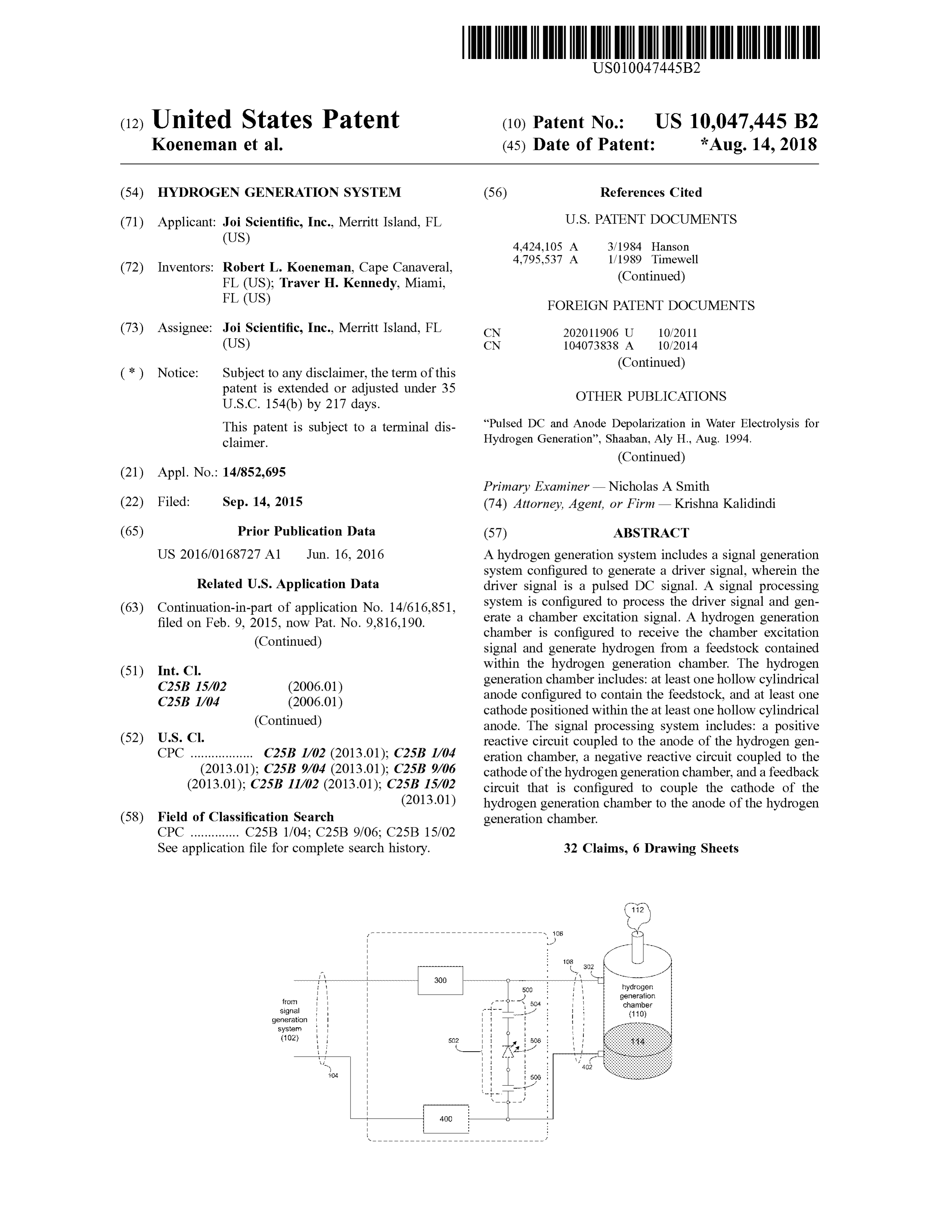
Related U .S . Application Data driver signal is a pulsed DC signal. A signal processing (63 ) Continuation -in -part of application No. 14 /616 ,851, system is configured to process the driver signal and gen filed on Feb . 9 , 2015 , now Pat. No . 9 ,816 , 190 . erate a chamber excitation signal. A hydrogen generation chamber is configured to receive the chamber excitation ( Continued ) signal and generate hydrogen from a feedstock contained (51) Int. Ci. within the hydrogen generation chamber. The hydrogen C25B 15 /02 ( 2006 . 01) generation chamber includes : at least one hollow cylindrical C25B 1/04 anode configured to contain the feedstock , and at least one ( 2006 .01) cathode positioned within the at least one hollow cylindrical (Continued ) anode. The signal processing system includes : a positive (52 ) U .S . CI. reactive circuit coupled to the anode of the hydrogen gen CPC .................. C25B 1/ 02 ( 2013 .01) ; C25B 1/04 eration chamber, a negative reactive circuit coupled to the (2013 .01) ; C25B 9 /04 ( 2013 .01); C25B 9/ 06 cathode of the hydrogen generation chamber, and a feedback (2013 .01 ); C25B 11 /02 (2013.01 ); C25B 15 /02 circuit that is configured to couple the cathode of the (2013 .01 ) hydrogen generation chamber to the anode of the hydrogen (58 ) Field of Classification Search generation chamber.
See application file for complete search history. 32 Claims, 6 Drawing Sheets - - - - - - - - - - - - - - - - - - - - - - - - - - - - - - - -
hydrogen
- 500 - - generation
chamber
generation
! i | 1
- 502 -
- - - -
- - - -
- -
- -
Page 2
US 10 ,Page
Related U .S . Application Data FOREIGN PATENT DOCUMENTS (60 ) Provisional application No.62/ 091 ,702, filed on Dec . DE 2713533 9 / 1978 15 , 2014 EP 0 975 822 B1 . 2 / 2004
(51 ) Int. Ci. JP 2006037214 A2 2 / 2006 C25B 9/ 06 ( 2006 .01 ) JP 2013231213 A 11/2013 C25B 1/02 ( 2006 .01) WO 2004097072 AL 11 /2004
WO WO 2004097072 A1 * 11/2004 C25B 1/ 04
C25B 9 /04 ( 2006 .01) WO 2007131254 A2 11/2007 C25B 11/02 ( 2006 . 01) WO 20100024965 AL 3 /2010
(56 ) References Cited WO 2011139893 AL 11/2011
U .S . PATENT DOCUMENTS WO 20140064470 A1 5 /2014 4 ,936 , 961 A 6 / 1990 Meyer wo 2015098058 A1 7 /2015
5 , 037,518 A 8 / 1991 Young et al. WO 2016054371 Al 4 /2016 6 ,332 ,434 B1 12/2001 DeSouza wo 2016068842 A1 5 /2016 6 ,790,324 B2 9 /2004 Chambers WO 2017004732 AL 1/2017
7 ,604 ,728 B2 10 / 2009 Schlager OTHER PUBLICATIONS
8 , 709 ,221 B1 * 4 / 2014 Smith . . . . . . . . . . . . . . . . . C25B 15 /02 “ Economical Hydrogen Production by Electrolysis Using Nano
8, 940 ,151 B1 1/ 2015 Hartvigsen et al. Pulsed DC ” , Dharmaraj, C . H . and AdishKumar, S ., International 8 , 940, 243 B1 1 /2015 Fahimi Journal of Energy and Environment, vol. 3, Issue 1, pp . 129 - 136 , 9 ,034 , 167 B25 /2015 Finfrock et al. 2012 .
9 ,353,451 B2 5 / 2016 Haywood “ Review of Pulsed Power for Efficient Hydrogen Production ” , 2006 / 0060464 A1 3 /2006 Chang Monk, N . and Watson, S . J.; International Journal of Hydrogen 2007/ 0080071 A1 4 / 2007 Perry , Jr. Energy , 41 ( 19 ), pp . 7782-7791, 2016 .
2007 /0272546 A1 * 11/ 2007 Matthews C25B 15 /02 " Effects of Geometry of Electrodes and Pulsating DC Input on 204 /230 . 2 Water Splitting for Production of Hydrogen ” , Mandal, Biswajit, 2008 /0277273 AL 11/2008 Logan Sirkar, A ., Shau , Abhra , De, P . and Ray, P., International Journal of 2008 /0302670 Al 12 / 2008 Boyle Renewable Energy Research , vol. 2 , No. 1, 2012 . 2009 /0045073 AL 2 / 2009 Stone et al. “ Influence of Electrical Conductivity and pH on Hydrogen Produc 2009/ 0266706 Al 10 / 2009 Fukui et al. tion Using Pulsed Discharge Over the Water Surface” , Ihara , 2009/0283402 AL 11/ 2009 Osman Takeshi, Ide , Yusuke, Nagata , Hideo , Yagyu , Yoshihito , Ohshima , 2010 / 0089746 A1 4 / 2010 Chang Tamiko , Kawasaki, Hiroharu , Suda , Yoshiaki; Plasma Science 2010 /0175941 A1 7/ 2010 Khodabakhsh (ICOPS), 2016 — Abstract.
2010 /0183931 A1 7 /2010 Hedman “ DC Electrical Breakdown of Water in a Sub -Micron Planar Gap ” , 2011/0146599 A1 * 6 / 2011 Sciban C25B 1 /04 Song, Chunrong and Wang , Pingshan ; IEEE 2009.
2011/ 0259757 Al 10 /2011 Vancina International Search Report ( ISR ) - PCT/US2015 /065854 — dated 2012 / 0012456 A 1/ 2012 Darrel Mar. 10 , 2016 — 6 pages ( including notification oftransmittal of the 2012 / 0058405 Al 3 / 2012 Kirchoff ISR and WO of the ISA ).
2012 /0104766 Al 5 / 2012 Davidson Written Opinion (WO ) of International Search Authority (ISA ) 2012 /0111734 Al 5 / 2012 Kramer PCT/US2015 /065854dated Mar. 10 , 2016 — 7 pages . 2012 /0152197 A1 6 / 2012 Innskeep International Search Report (ISR ) — PCT/US2015 /065785 _ dated 2012 /0175247 A1 7 / 2012 Darrel Mar. 4 , 2016 6 pages ( including notification of transmittal of the 2012 /0199472 A1 8 / 2012 Curfew ISR and WO of the ISA ) .
2012 /0222954 Al 9 /2012 Lothring Written Opinion (WO ) of International Search Authority (ISA ) 2013 /0118908 AL 5 /2013 Radu PCT/US2015/065785 — dated Mar. 4 , 2016 — 8 pages. 2014 /0048067 A1 2/ 2014 McGill http ://web .archive .org /web /20130130100756 /https:// en .wikipedia . 2014 /0363806 Al 12/ 2014 Fillipone org /wiki/Band -stop _ filter - Jan . 20 , 2013 . 2014 /0367272 A1 * 12 /2014 Haywood .............. C25B 15 /08 “ Water Eletrolysis with Voltage Inductive Pulses” , Vanags, Martins
2016 /0068976 A1 3 / 2016 Yoshida et al. et al., Electrolysis, Chapter 2 , 2012 .
2017 / 0088958 Al * 3/ 2017 Koeneman .............. C25B 11/02 * cited by examiner
Page 3
Drawing sheet — no readable text.
Page 4
Drawing sheet — no readable text.
Page 5
atent Aug. 14 , 2018 Sheet 3 of 6 US 10 ,047,445 B2 hydrogen eration chamber )
108 -- - - - - - 1 * 1
106 -- - I i 1 - - - - - - - - - - - - - - Jw - - - - - - - - - - - - - -
FIG 308 310 312 —
i 1 - - -
which
Page 6
atent Aug. 14 , 2018 Sheet 4 of 6 US 10 ,047,445 B2 E ydrogen erationchamber :)
108 - - -
? ?? ??? ??? ??? ?? ?? ? ???? ?? ?? ??? ??? ?? ?? ?? ? ?? ?? - - - -- - - - -- - - - -- - - -
400 ? ? 1 - -
FIG
300 -
- - - ?? -- - - - - - - -- - - - - - - - -- - -- - - -
Page 7
atent Aug. 14 , 2018 Sheet 5 of 6 US 10 ,047,445 B2 hydrogen eration chamber )
302 w ww - 4 402
106 wwwwww
* * ** ** * ** * * * * ** * * * ** * **
FIG
what
502 -
tanke med
* * - - - * ' - -- - - - - - - - -- -- -- - - - - -- - -- - - - - - -- - - --
. . Vlore
from genration
Page 8
Drawing sheet — no readable text.
Page 9
HYDROGEN GENERATION SYSTEM and temperature), contain (due to its very small molecule structure ), and transport. Accordingly , pressure , tempera
RELATED APPLICATION (S ) ture , flammability, explosiveness , and low ignition energy requirement are all significant safety issues concerning the
This application claims the benefit of U .S . Provisional 5 widespread use of hydrogen .
Patent Application No. 62/091,702 , entitled “ Polyphonic
Methods and Related Apparatus and Arrangements” and SUMMARY OF DISCLOSURE filed on 15 Dec . 2014 , the entire contents of which is herein In one implementation , a hydrogen generation system incorporated by reference .
This application is a Continuation -in -Part (CIP ) of U . S . 10 includes a signal generation system configured to generate a Utility patent application Ser. No. 14/616 ,851, entitled driver signal. The driver signal is a pulsed DC signal . A “ Energy Extraction System and Methods” and filed on 09 signal processing system is configured to process the driver Feb . 2015, the entire contents of which are herein incorpo signal and generate a chamber excitation signal. A hydrogen rated by reference . generation chamber is configured to receive the chamber excitation signal and generate hydrogen from a feedstock
TECHNICAL FIELD contained within the hydrogen generation chamber. The hydrogen generation chamber includes : at least one hollow
This disclosure relates to hydrogen generation systems cylindrical anode configured to contain the feedstock and at and , more particularly , to hydrogen generation systems that least one cathode positioned within the at least one hollow use hydrolysis to generate hydrogen from feedstock . 20 cylindrical anode. The signal processing system includes: a positive reactive circuit coupled to the anode of the hydro
BACKGROUND gen generation chamber, a negative reactive circuit coupled to the cathode of the hydrogen generation chamber, and a
Currently, the majority of the energy consumed by the feedback circuit that is configured to couple the cathode of developed world has its origins in fossil fuels. Unfortu - 25 the hydrogen generation chamber to the anode of the hydro nately , there are many well -documented problems associ - gen generation chamber.
ated with over -reliance upon energy generated from fossil One or more of the following features may be included . fuels, such as: pollution and climate change caused by the The signal generation system may include: a pulsed DC emission of greenhouse gases: the finite nature of fossil fuels source configured to generate a pulsed DC source signal, a and the dwindling reserves of such carbon -based energy 30 mono - directional blocking circuit configured to receive the sources ; and the concentration of control of petroleum -based pulsed DC source signal and generate the driver signal, and energy supplies by various volatile countries and OPEC . a filter circuit configured to filter the driver signal and Accordingly, there is a need for alternative sources of remove AC components . The positive reactive circuit may energy. One such alternative energy source includes hydro include an inductive component and a capacitive compo gen generation systems that produce hydrogen via hydroly - 35 nent. The inductive component may be in parallel with the sis. Ideally, such hydrogen generation systems would be capacitive component. The capacitive component may be capable of producing hydrogen gas without the presence of sized based , at least in part, upon one or more physical oxygen , wherein such hydrogen may be used for industrial, characteristics of the hydrogen generation chamber. The commercial and residential purposes . capacitive component may be sized based , at least in part, For example, when greater than 99 % pure , hydrogen may 40 upon one or more physical characteristics of the feedstock be used in generator cooling, steel production , glass pro - contained within the hydrogen generation chamber. The duction , and semiconductor and photovoltaic cell produc - negative reactive circuit may include an inductive compo tion . When less than 99 % pure , hydrogen may be used in nent and a capacitive component . The inductive component various industries, such as the aerospace industry, the animal may be in parallel with the capacitive component. The feed industry , the automotive industry , the baking industry , 45 capacitive component may be sized based , at least in part, the chemical industry , the ethanol industry , the food pro - upon one or more physical characteristics of the hydrogen cessing industry , the dairy industry, the meat industry , the generation chamber. The capacitive component may be manufacturing industry, themedical industry , the hospitality sized based , at least in part, upon one or more physical industry , the laundry /uniform industry , the marine and off characteristics of the feedstock contained within the hydro shore industry , the military and defense industry, the mining 50 gen generation chamber. The feedback circuit may include a industry, the oil and gas industry, the paper/corrugating capacitive component. The capacitive component may be industry , the pharmaceutical industry, the rubber industry , sized based , at least in part, upon one or more physical the steel and metals industry , the tobacco industry , the characteristics of the hydrogen generation chamber. The transportation industry , the wire and cable industry , and the capacitive component may be sized based , at least in part, education industry . 55 upon one or more physical characteristics of the feedstock Unfortunately , there are a number of significant hurdles contained within the hydrogen generation chamber. The that prevent the widespread use of hydrogen in commercial, capacitive component may include two discrete capacitors . industrial, and residential applications. These hurdles A first of the discrete capacitors may be coupled to the anode include cost, efficiency , and safety . First and foremost of the hydrogen generation chamber. A second of the dis creating hydrogen gas in a traditional manner is inefficient 60 ?rete capacitors may be coupled to the cathode of the and costly , or even environmentally harmful when produced hydrogen generation chamber . The feedback circuit may via reformation (i.e ., the primary commercial method ). include an asymmetrically conductive component. The Secondly , hydrogen 's very low mass and energy density asymmetrically conductive component may be positioned makes it challenging to get enough mass of hydrogen gasb etween the two discrete capacitors. The at least one cathode safely in one place to be of practical value to a user. The 65 may be positioned along a longitudinal centerline of the at result is that hydrogen has been prohibitively expensive to least one hollow cylindrical anode . The at least one cathode produce , compress, cryogenically cool, maintain (at pressure may be constructed , at least in part, of tungsten . The at least
Page 10
one hollow cylindrical anode may be constructed , at least in and remove AC components. A signal processing system is part, of graphite . The at least one hollow cylindrical anode configured to process the driver signal and generate a may have an inside diameter that is 2 , 400 % to 2 ,600 % of an chamber excitation signal. A hydrogen generation chamber outside diameter of the at least one cathode positioned is configured to receive the chamber excitation signal and within the cylindrical anode. The at least one hollow cylin - 5 generate hydrogen from a feedstock contained within the drical anode may have an inner diameter of 25 .0 millimeters hydrogen generation chamber. The hydrogen generation and the at least one cathode positioned within the hollow chamber includes : at least one hollow cylindrical anode cylindrical anode may have an outside diameter of 1 . Omil configured to contain the feedstock , and at least one cathode limeter. The at least one cathode positioned within the at positioned within the at least one hollow cylindrical anode . least one hollow cylindrical anode may have a longitudinal 10 The signal processing system includes: a positive reactive length that is 190 % to 210 % of the inside diameter of the at circuit coupled to the anode of the hydrogen generation least one hollow cylindrical anode. The at least one cathode chamber and including an inductive component and a positioned within the at least one hollow cylindrical anode capacitive component, a negative reactive circuit coupled to may have a longitudinal length of 50 .0 millimeters .
In another implementation , a hydrogen generation system 15 the cathode of the hydrogen generation chamber and includ includes a signal generation system configured to generate a ing an inductive component and a capacitive component , driver signal. The signal generation system includes : a and a feedback circuit that is configured to couple the pulsed DC source configured to generate a pulsed DC source cathode of the hydrogen generation chamber to the anode of signal, a mono - directional blocking circuit configured to the hydrogen generation chamber. The at least one hollow receive the pulsed DC source signal and generate a driver 20 cylindrical anode has an inside diameter that is 2 ,400 % to signal, and a filter circuit configured to filter the driver signal 2 ,600 % of an outside diameter of the at least one cathode and remove AC components. A signal processing system is positioned within the cylindrical anode . The at least one configured to process the driver signal and generate a cathode positioned within the at least one hollow cylindrical chamber excitation signal. A hydrogen generation chamber anode has a longitudinal length that is 190 % to 210 % of the is configured to receive the chamber excitation signal and 25 inside diameter of the at least one hollow cylindrical anode . generate hydrogen from a feedstock contained within the One or more of the following features may be included . hydrogen generation chamber. The hydrogen generation The positive reactive circuit may be configured as a band chamber includes : at least one hollow cylindrical anode stop filter. The negative reactive circuit may be configured as configured to contain the feedstock , and at least one cathode a band -stop filter.
positioned within the at least one hollow cylindrical anode. 30 The details of one or more implementations are set forth The signal processing system includes: a positive reactive in the accompanying drawings and the description below . circuit coupled to the anode of the hydrogen generation chamber and including an inductive component and a Other features and advantages will become apparent from the description , the drawings, and the claims.
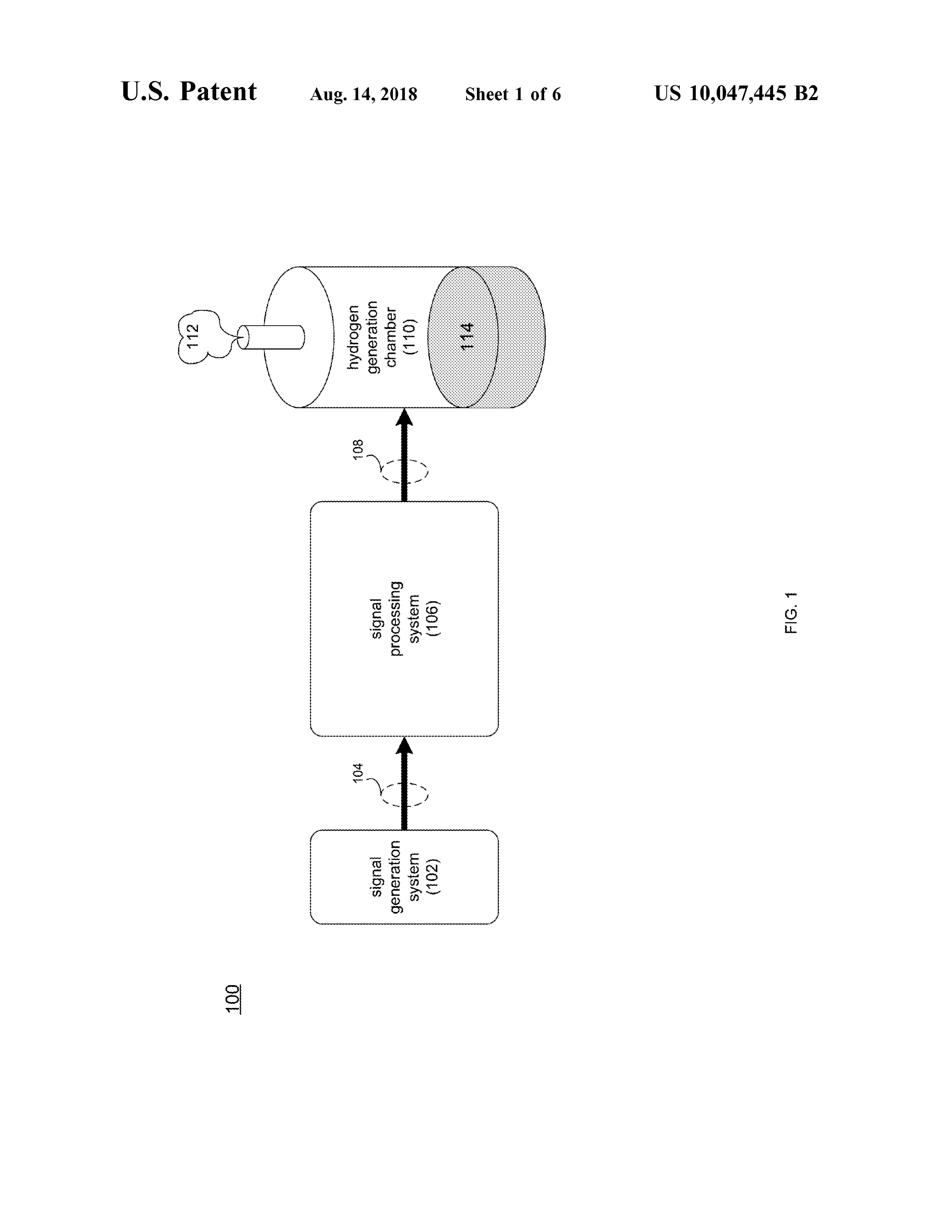
capacitive component, a negative reactive circuit coupled to the cathode of the hydrogen generation chamber and includ - 35 ing an inductive component and a capacitive component, BRIEF DESCRIPTION OF THE DRAWINGS and a feedback circuit that is configured to couple the FIG . 1 is a diagrammatic view of a hydrogen generation cathode of the hydrogen generation chamber to the anode of system ;
the hydrogen generation chamber.
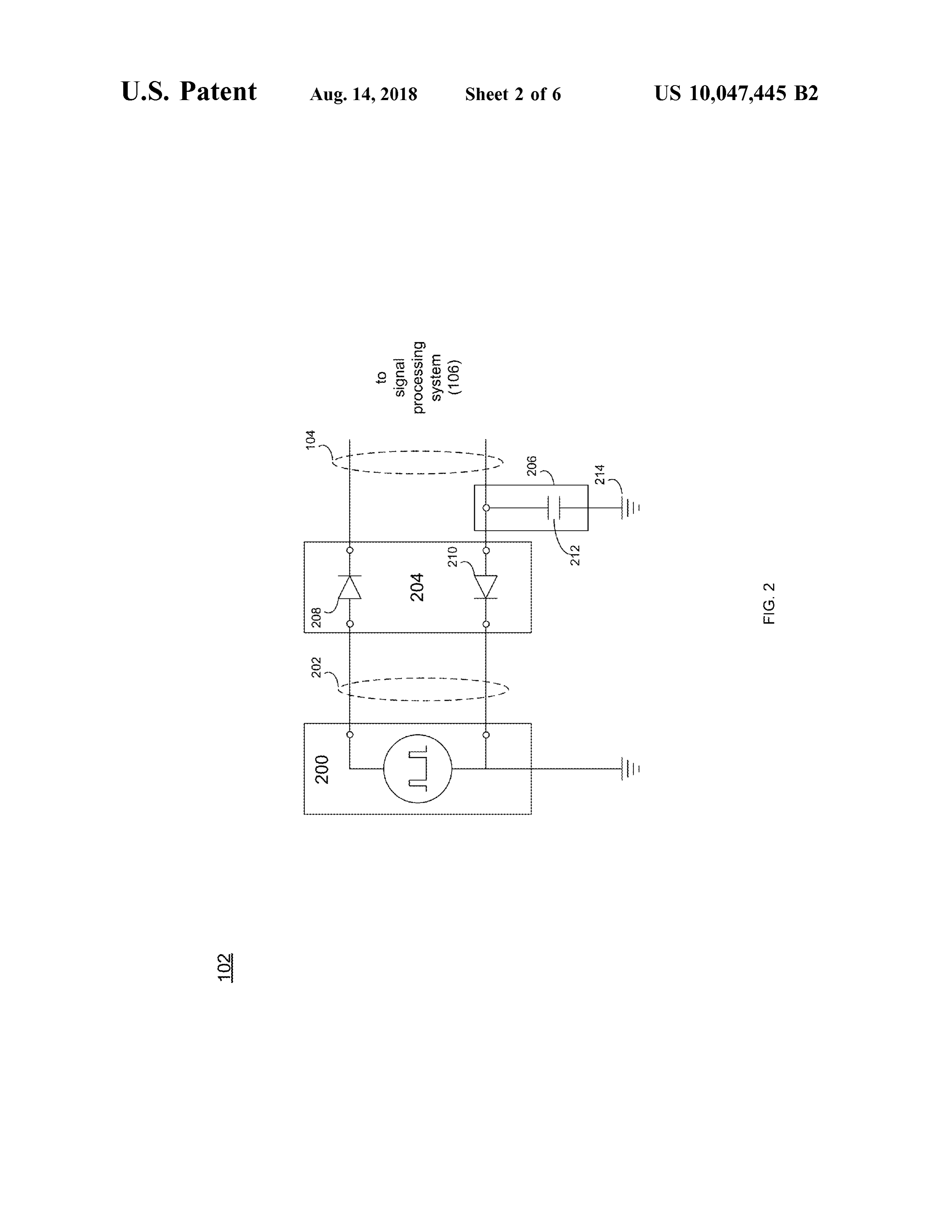
One or more of the following features may be included . 40 FIG . 2 is a diagrammatic view of a signal generation The feedback circuit may include a capacitive component system included within the hydrogen generation system of The capacitive component may be sized based , at least in FIG . 1 ;
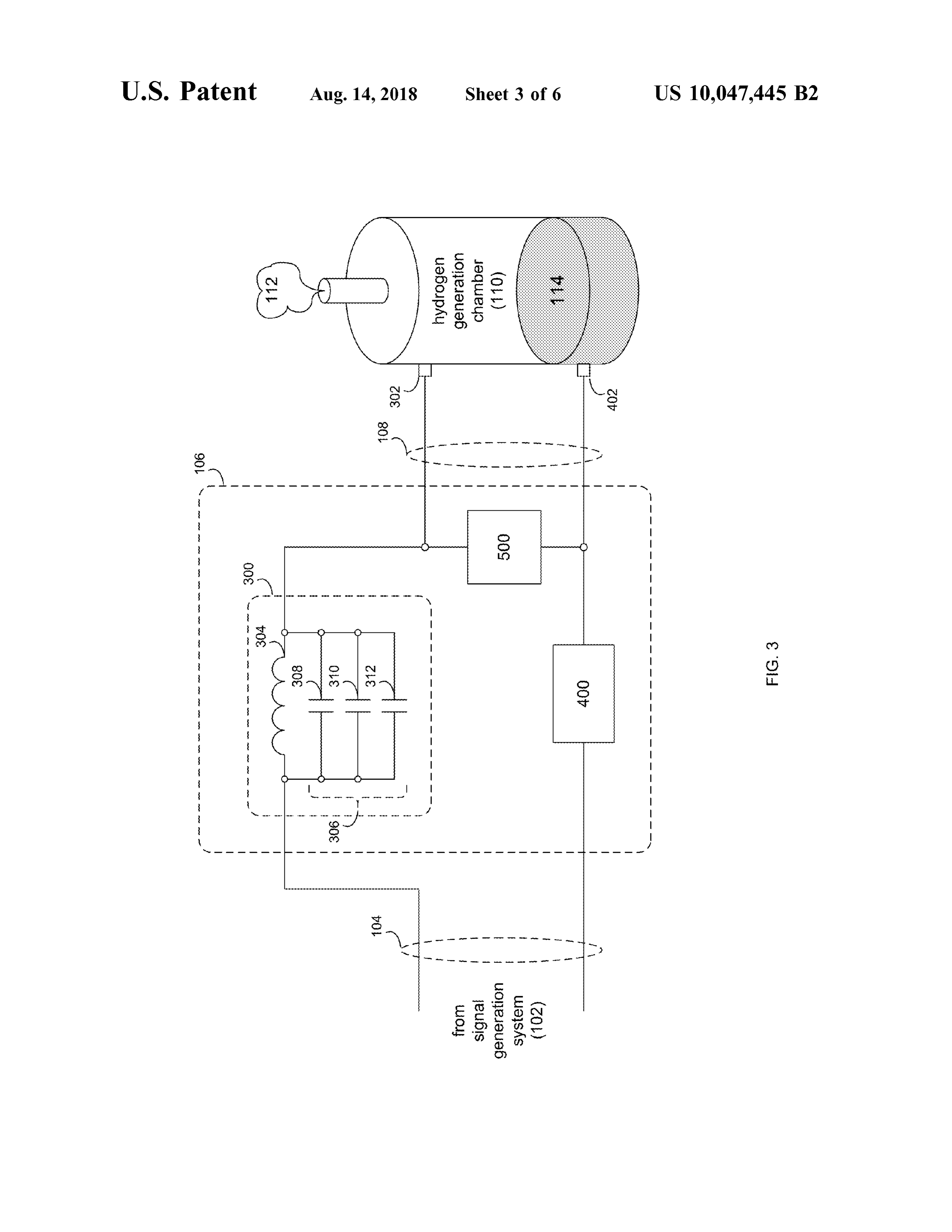
part, upon one or more physical characteristics of the FIG . 3 is a diagrammatic view of a positive reactive hydrogen generation chamber. The capacitive component circuit included within the hydrogen generation system of may be sized based , at least in part, upon one or more 45 FIG . 1 ;
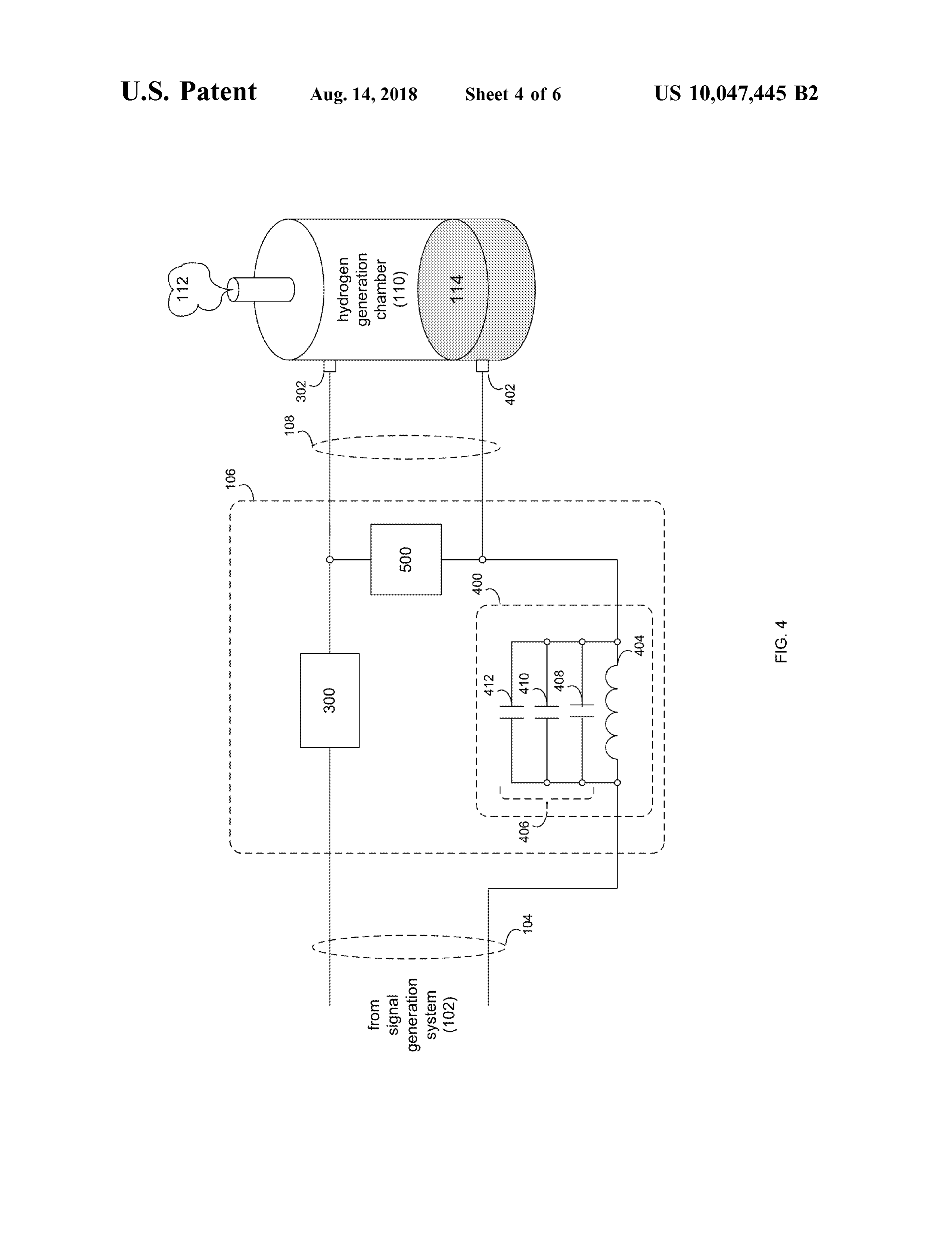
physical characteristics ofthe feedstock contained within the FIG . 4 is a diagrammatic view of a negative reactive hydrogen generation chamber. The at least one hollow circuit included within the hydrogen generation system of cylindrical anode may have an inside diameter that is FIG . 1 :
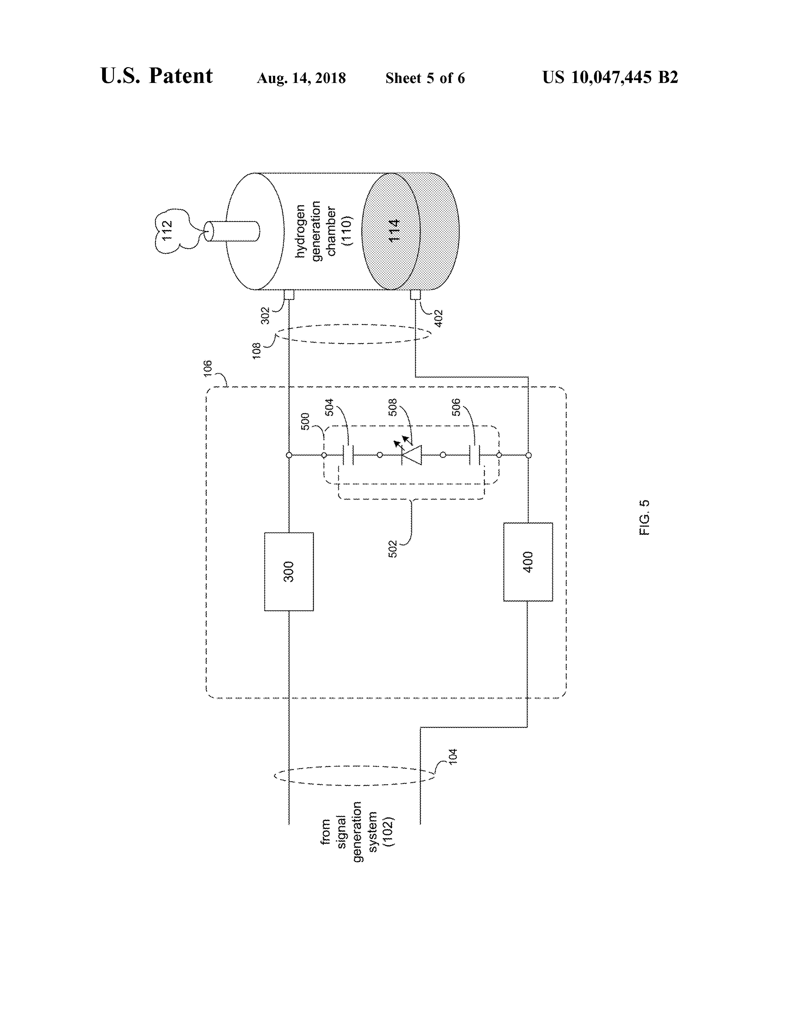
2 ,400 % to 2 ,600 % of an outside diameter of the at least one FIG . 5 is a diagrammatic view of a feedback circuit cathode positioned within the cylindrical anode . The at least 50 included within the hydrogen generation system of FIG . 1; one hollow cylindrical anode may have an inner diameter of and 25 .0 millimeters and the at least one cathode positioned FIG . 6 is a diagrammatic view of a hydrogen generation within the hollow cylindrical anode may have an outside chamber included within the hydrogen generation system of diameter of 1. 0 millimeter. The at least one cathode posi- FIG . 1 .
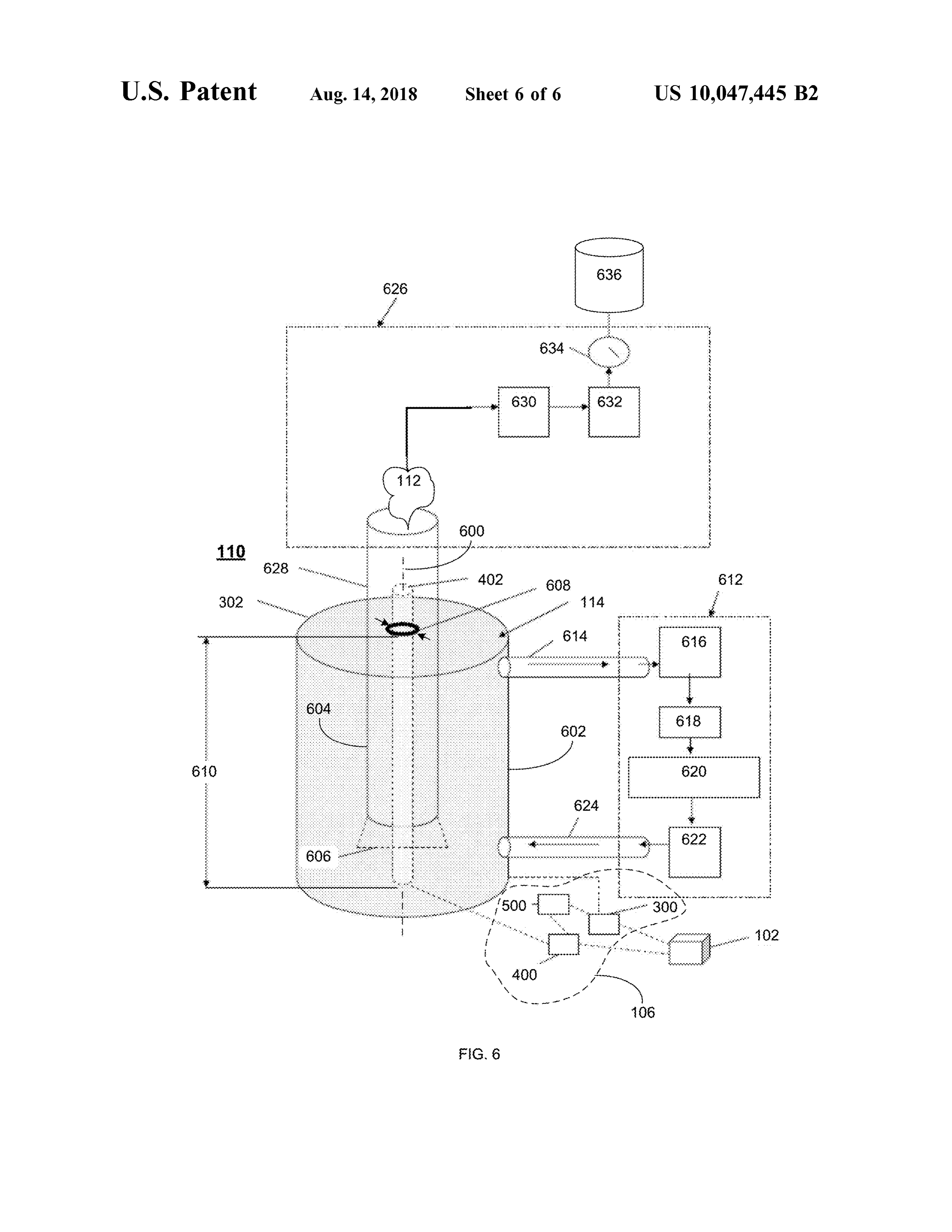
tioned within the at least one hollow cylindrical anode may 55 Like reference symbols in the various drawings indicate have a longitudinal length that is 190 % to 210 % of the inside like elements .
diameter of the at least one hollow cylindrical anode. The at least one cathode positioned within the at least one hollow DETAILED DESCRIPTION OF THE cylindrical anode may have a longitudinal length of 50 .0 PREFERRED EMBODIMENTS millimeters . 60
In another implementation , a hydrogen generation system Hydrogen Generation System Overview : includes a signal generation system configured to generate a Referring to FIG . 1, there is shown hydrogenation gen driver signal. The signal generation system includes: a eration system 100 . Hydrogen generation system 100 may pulsed DC source configured to generate a pulsed DC source include signal generation system 102 configured to generate signal, a mono -directional blocking circuit configured to 65 a driver signal 104 . An example of driver signal 104 may receive the pulsed DC source signal and generate a driver include but is not limited to a pulsed DC signal. Driver signal, and a filter circuit configured to filter the driver signal signal 104 may be provided to signal processing system 106 ,
Page 11
wherein signal processing system 106 may be configured to driver signal 104 . Signal generation system 102 may also process driver signal 104 and generate a chamber excitation include filter circuit 206 configured to filter driver signal 104 signal 108 . and remove AC components .
Hydrogen generation system 100 may include hydrogen Mono -directional blocking circuit 204 may include at generation chamber 110 that may be configured to receive 5 least one asymmetrically conductive component, an example ofwhich includes but is not limited to a diode (e.g., chamber excitation signal 108 and generate hydrogen 112 a Schottky diode ), such as a 1N4003G diode available from (e.g., gaseous hydrogen ) from feedstock 114 contained ON Semiconductor configured to function as blocking within hydrogen generation chamber 110 .
As discussed above, hydrogen 112 produced by hydrogen 10 diodes . In a typical configuration , mono -directional block generation system 100 may be used with various industries , components204208may ing circuit include two asymmetrically conductive , 210 . Filter circuit 206 may include capaci such as the aerospace industry , the animal feed industry, the automotive industry , the baking industry, the chemical tor 212 coupled to ground 214 that is sized to remove any undesirable AC signal components . An example of capacitor industry , the ethanol industry , the food processing industry, 212 may include a 470 microfarad capacitor available from the dairy industry, the meat industry , the manufacturing 15 Mouser Electronics.
industry , the medical industry, the hospitality industry , the One implementation of driver signal 104 generated by laundry /uniform industry , the marine and offshore industry , signal generation system 102 may be a driver signal that has the military, the mining industry , the oil and gas industry, the a duty cycle of less than 25 % . Specifically and in a preferred paper /corrugating industry , the pharmaceutical industry, the embodiment, driver signal 104 may have a duty cycle rubber industry, the steel and metals industry, the tobacco 20 between 6 .5 % and 13 % , wherein during 6.5 % -13 % of the industry , the transportation industry, the wire and cable waveform of driver signal 104 , driver signal 104 has an industry , and the education industry . amplitude of 4 .5 to 10 VDC and during 87 % - 93 .5 % of the As discussed above, hydrogen generation system 100 may waveform of driver signal 104 , driver signal 104 has an generate hydrogen 112 (e . g ., gaseous hydrogen ) from feed amplitude of O VDC . The above -described implementations stock 114 contained within hydrogen generation chamber 25 of driver signal 104 are intended to be illustrative and not all 110 . One example of feedstock 114 may include but is not inclusive. Accordingly , these are intended to be merely limited to sea water. Accordingly and in certain implemen examples of the various driver signals that be utilized by tations, hydrogen generation system 100 may be positioned signal generation system 102 .
proximate a source of feedstock 114 . Alternatively , feed - Operation of the Signal Generation System : stock 114 may be provided to hydrogen generation system 30 Concerning driver signal 104 generated by signal genera 100 via a delivery network , not shown. tion system 102 , the rise time of driver signal 104 may be Hydrogen generation chamber 110 , when filled with an critical to the overall function and performance of hydrogen electrolytic fluid (e . g ., feedstock 114 ), may react like a generation chamber 110 . Accordingly, a rise time as close to variable capacitive load with corresponding variable imped - instantaneous as possible (e .g ., as close to a truly vertical ance values . When a Pulsed DC signal ( e . g ., chamber 35 sweep ) may result in the most efficient operation of hydro excitation signal 108 ) is applied to hydrogen generation gen generation chamber 110 . Further, the amplitude of driver chamber 110 , the result may be a reactive load . Hydrogen signal 104 may be increased /decreased to vary the perfor generation chamber 110 may complete the closed circuit mance of hydrogen generation chamber 110 and the quantity path that forms the load factor during the ON Cycle Pulse of hydrogen 112 produced .
(OCP ) of chamber excitation signal 108 . 40 Signal generation system 102 may be configured to pro The electrolytic fluid ( e. g ., feedstock 114 ) may change vide for adjustments in the pulse width and/ or duty cycle of state both chemically and electronically during the OCP of driver signal 104 . Any pulse width and/ or duty cycle adjust chamber excitation signal 108 . These changes may affect the ments may be based on the desired chamber performance . charge state of feedstock 114 , changing the above -described The timing of the duty cycle of driver signal 104 may capacitive and impedance values , which may be monitored 45 establish a base frequency for driver signal 104 . In a via a differential potential voltage measurement across the preferred embodiment, the pulse base frequency of driver anode and cathode of hydrogen generation chamber 110 . signal 104 may range from 100 hertz to 10 kilohertz (how Signal processing system 106 may provide impedance ever, frequencies outside of this range may also be utilized ) . matching and capacitive balancing during the OCP of cham - The diodes (e .g ., asymmetrically conductive components ber excitation signal 108 . Balancing of signal processing 50 208 , 210 ) utilized in mono -directional blocking circuit 204 system 106 may accomplish multiple functions, including may perform several functions. Typically , Schottky diodes but not limited to lowering reactive circuit current demand have forward biases of approximately 1 mA in the range while directing chamber excitation signal 108 with a given 0 . 15 to 0 . 46 volts . This lower forward voltage may provide base frequency across the electrodes of hydrogen generation for higher switching speeds and better system efficiency, chamber 110 . 55 wherein Schottky diodes are considered to have essentially During the OFF Cycle Pulse (OFCP ) of chamber excita - instant reverse recovery time.
tion signal 108 , the inductive and capacitive sections of The two diodes ( e.g ., asymmetrically conductive compo signal processing system 106 may receive energy from nents 208 , 210 ) may provide a first stage voltage clamp that hydrogen generation chamber 110 as hydrogen generation may enhance rise time and forward current build up , which chamber 110 discharges . 60 may be important during each startup of the OCP . The Signal Generation System Configuration : blocking diodes (e . g ., asymmetrically conductive compo Referring to FIG . 2, there is shown one implementation of nents 208 , 210) may provide transient voltage suppression signal generation system 102 . Signal generation system 102 during initial charging ofhydrogen generation chamber 110 . may include pulsed DC source 200 configured to generate This may allow hydrogen generation chamber 110 to reach pulsed DC source signal 202. Signal generation system 102 65 full voltage amplitude in the least amount time. may include mono -directional blocking circuit 204 config - The two diodes ( e. g ., asymmetrically conductive compo ured to receive pulsed DC source signal 202 and generate nents 208 , 210 ) may also prevent voltage returned from
Page 12
hydrogen generation chamber 110 from interfering with 406 . One example of inductive component 404 may include pulsed DC source signal 202 , thus isolating the downstream a 100 microhenry inductor available from Mouser Electron circuit ( e.g ., signal processing system 106 ) during the off ics . Inductive component 404 may be in parallel with cycle while the reactive part of this circuit is in the recovery capacitive component 406 . Capacitive component 406 may phase and exposed to a return voltage in the range of 0 . 90 5 be sized based , at least in part, upon one or more physical VDC to 4 .5 VDC . characteristics of hydrogen generation chamber 110 ( e . g., Positive Reactive Circuit Configuration : size, shape, electrode type , configuration and dimensions ) Referring to FIG . 3 , there is shown one implementation of and /or one or more physical characteristics of feedstock 114 signal processing system 106 , wherein signal processing (e. g ., feedstock type and contents included therein ) con system 106 is shown to include positive reactive circuit 300 . 10 tained within hydrogen generation chamber 110 . Positive reactive circuit 300 may be coupled to anode 302 of Inductive component 404 may be constructed of/formed hydrogen generation chamber 110 . from several individual inductors that may be arranged (in a In one implementation , positive reactive circuit 300 may parallel and/ or series configuration ) to achieve the desired include inductive component 304 and capacitive component inductance value . Additionally (and as will be discussed 306 . One example of inductive component 304 may include 15 below ), capacitive component 406 may be constructed a 10 microhenry inductor available from Mouser Electron of/formed from several individual capacitors that are ics . Inductive component 304 may be in parallel with arranged ( in a parallel and /or series configuration ) to achieve capacitive component 306 . Capacitive component 306 may the desired capacitive value.
be sized based , at least in part, upon one or more physical In one implementation , capacitive component 406 may characteristics of hydrogen generation chamber 110 ( e.g ., 20 include a plurality of discrete capacitors. For example , size, shape, electrode type, configuration and dimensions ) capacitive component 406 may include three discrete and /or one or more physical characteristics of feedstock 114 capacitors (e.g., capacitors 408 , 410, 412 ) arranged in par (e .g ., feedstock type and contents included therein ) con - allel to form a parallel capacitor circuit. In one particular tained within hydrogen generation chamber 110 . implementation , capacitor 408 may be a 1 microfarad Inductive component 304 may be constructed of/ formed 25 capacitor available from Mouser Electronics , capacitor 410 from several individual inductors thatmay be arranged in a may be a 1 picofarad capacitor available from Mouser parallel and/ or series configuration ) to achieve the desired Electronics , and capacitor 412 may be a 5 nanofarads inductance value . Additionally (and as will be discussed capacitor available from Mouser Electronics. This parallel below ), capacitive component 306 may be constructed capacitor circuit ( e . g ., the parallel combination of capacitors of/ formed from several individual capacitors that are 30 408 , 410 , 412 ) may be coupled in parallel with inductive arranged ( in a parallel and/or series configuration ) to achieve component 404 , wherein the output of the parallel capacitor the desired capacitive value . circuit ( e.g ., the parallel combination of capacitors 408 , 410 , In one implementation , capacitive component 306 may 412 ) and inductive component 304 may be provided to include a plurality of discrete capacitors . For example , cathode 402 of hydrogen generation chamber 110 . capacitive component 306 may include three discrete 35 In this particular implementation , negative reactive circuit capacitors (e . g ., capacitors 308 , 310 , 312 ) arranged in par - 400 may be configured as a band -stop filter. As is known in allel to form a parallel capacitor circuit. In one particular the art and in signal processing, a band -stop filter (or implementation , capacitor 308 may be a 45 microfarad band -rejection filter ) is a filter that passes most frequencies capacitor available from Mouser Electronics , capacitor 310 unaltered (i.e ., unattenuated ), while attenuating those fre may be a 1 picofarad capacitor available from Mouser 40 quencies that are within a defined range . As with any other Electronics, and capacitor 312 may be a 5 nanofarads LC filter, the particular range of frequencies that are attenu capacitor available from Mouser Electronics. This parallel a ted may be defined based upon the value of the capacitors capacitor circuit ( e . g ., the parallel combination of capacitors ( e . g ., capacitors 408, 410 , 412 ) and inductors ( e . g ., inductive 308 , 310 , 312 ) may be coupled in parallel with inductive component 404) included within negative reactive circuit component 304, wherein the output of the parallel capacitor 45 400 .
circuit (e.g., the parallel combination of capacitors 308 , 310 ,
Feedback Circuit Configuration :
312 ) and inductive component 304 may be provided to Referring to FIG . 5 , there is shown one implementation of anode 302 of hydrogen generation chamber 110 . signal processing system 106 , wherein signal processing In this particular implementation , positive reactive circuit system 106 is shown to include feedback circuit 500 . Feed 300 may be configured as a band -stop filter. As is known in 50 back circuit 500 may be configured to couple anode 302 of the art and in signal processing, a band -stop filter ( or hydrogen generation chamber 110 to cathode 402 of hydro band -rejection filter ) is a filter that passes most frequencies gen generation chamber 110 .
unaltered (i.e ., unattenuated ), while attenuating those fre - In one implementation , feedback circuit 500 may include quencies that are within a defined range . As with any other capacitive component 502. Capacitive component 502 may LC filter, the particular range of frequencies that are attenu - 55 be sized based , at least in part, upon one or more physical ated may be defined based upon the value of the capacitors characteristics of hydrogen generation chamber 110 ( e. g ., ( e .g ., capacitors 308 , 310 , 312 ) and inductors (e . g ., inductive size , shape, electrode type , configuration and dimensions) component 304 ) included within positive reactive circuit and / or one or more physical characteristics of feedstock 114 300. ( e. g ., feedstock type and contents included therein ) con Negative Reactive Circuit Configuration : 60 tained within hydrogen generation chamber 110 . Referring to FIG . 4 , there is shown one implementation of Capacitive component 502 may include two discrete signal processing system 106 , wherein signal processing capacitors ( e . g ., capacitors 504 , 506 ). In one particular system 106 is shown to include negative reactive circuit 400 . implementation , capacitor 504 may be a 1 microfarad Negative reactive circuit 400 may be coupled to cathode 402 capacitor available from Mouser Electronics and capacitor of hydrogen generation chamber 110 . 65 506 may be a 1 microfarad capacitor available from Mouser In one implementation , negative reactive circuit 400 may Electronics , A first of the discrete capacitors ( e. g ., capacitor include inductive component 404 and capacitive component 504 ) may be coupled to anode 302 of hydrogen generation
Page 13
chamber 110 . A second of the discrete capacitors (e.g ., tion chamber 110 may change from a charge state to a reset discrete capacitor 506 ) may be coupled to cathode 402 of discharge cycle . During this OFF cycle , all electronic inter hydrogen generation chamber 110 . actions may be energized from energy recovered ( or har Feedback circuit 500 may include asymmetrically con vested ) from hydrogen generation chamber 110 . ductive component 508 , wherein asymmetrically conductive 5 The charge amplitude of hydrogen generation chamber component 508 may be positioned between the two discrete 110 may have a characteristic fast decline from greater than capacitors (e.g ., capacitors 504 , 506 ). One example of 3 .5 VDC to less than 1 .4 VDC . The decline curve sweep asymmetrically conductive component 508 may include but angle may be dependent on the pulsed DC input frequency is not limited to a diode ( e . g ., a light emitting diode), such and the configuration of the reaction circuits (e . g ., positive as a RED /diffused T - 1 (3 mm ) 696 -SSL -LX3044ID avail- 10 reaction circuit 300 and negative reaction circuit 400 ). able from Mouser Electronics . During the cutoff initiation , the first decline sequence to Operation of the Signal Processing System : occur is the collapse of the electron density column sur Concerning the reactive circuits (e .g ., positive reactive rounding cathode 402 . This high density electron column circuit 300 and negative reactive circuit 400 ), these circuits may be held in place by the induced magnetic field that is a may incorporate an inductor in parallel with plurality of 15 result of the OCP. This collapse may cause an electronic capacitors ( as discussed above ). Upon the initiation of the flashback ( or rapid energy release ) from hydrogen genera OCP, these inductors may oppose any rise in current. This tion chamber 110 to the reactive circuit ( e. g ., positive opposition may be part of the electronic clamp during the reaction circuit 300 and / or negative reaction circuit 400 ), rise time of the OCP. The capacitors in parallel with the which is similar to an electrostatic discharge and may inductor may start to charge during the rise time of the OCP 20 provide the electrolytic fluid ( e .g ., feedstock 114 ) with a and provide a path for electron flow in the direction of pathway to start a change in state of polarity releasing hydrogen generation chamber 110 . additional stored energy .
These capacitors may not be able to overcome the voltage Once the electron column proximate cathode 402 starts to amplitude of hydrogen generation chamber 110 and , there collapse , there is a fast rise in potential on negative reactive fore , may not be able to discharge during the OCP time. As 25 circuit 402 . At this point, there may be an imbalance with these capacitors may be relatively small and may reach full positive reactive circuit 302 . The inductor within negative charge status during the rise time of OCP and may remain reactive circuit 402 may have a rise in potential imposing an charged during the duration of the OCP. impedance value that may allow the parallel capacitors to The slight opposition to current change (by the inductor discharge in the opposite direction to the charge state during during the OCP rise timemay quickly dissipate , wherein the 30 the OCP. This situation may create a latching circuit poten inductor opposes current change based upon magnetically tial through hydrogen generation chamber 110 as the path induced resistance to the current flow . way for electron flow .
Hydrogen generation chamber 110 may function as a load The return energy from hydrogen generation chamber 110 for signal processing system 106 , wherein hydrogen gen - may be a DC signal with embedded AC components, eration chamber 110 may have a varying internal resistance 35 wherein these AC components may be relatively small in and a varying voltage amplitude . Hydrogen generation amplitude . The AC components may be driven by the chamber 110 may behave similarly to an inductive /capaci molecular polarity shift after the cutoff sequence is initiated tive electronic component, wherein variations may occur and the imbalance of the charge state ofhydrogen generation based upon varying electrolytic conditions that can vary chamber 110 . The DC component produced by hydrogen dramatically during the rise time of the OCP. These varying 40 generation chamber 110 may be clamped to swing the AC conditions may continue during the length of the duty cycle wave into the positive range .
and may be in the form of a charge ion state triggering The capacitors in the reactive circuits ( e. g ., positive charging of hydrogen generation chamber 110 . The electron reaction circuit 300 and / or negative reaction circuit 400 ) density within hydrogen generation chamber 110 may may charge stabilize after the electrostatic release from the increase dramatically within hydrogen generation chamber 45 DC component. The inductors may provide timing 110 . This electron density may be at its greatest at a sequences and preload for capacitor charge /discharge circumference slightly larger than the outer diameter of sequence while minimizing circuit resistance at peak input cathode 402. values . The capacitors may subsequently discharge under The ON cycle rise time and duration of the duty cyclemay the influence of the AC components . The result may be an cause a molecular polarity shift within the electrolytic fluid 50 amplification of the embedded frequency waves providing a ( e . g., feedstock 114 ). This molecular polarity shift may have charge/discharge cycle at these given frequencies . This a corresponding electromagnetic/ electrostatic component. sequence may continue until the molecular polarity rotation Due to the shape and geometry of hydrogen generation of hydrogen generation chamber 110 is stabilized or the chamber 110 and without a defined electron flow pathway , charge imbalance of the reactive circuit (e .g., positive reac the electromagnetic component will have a chaotic charac - 55 tion circuit 300 and /or negative reaction circuit 400 ) is teristic , wherein this chaotic characteristic may assist in the diminished .
molecular splitting of gas atoms from the water molecules Feedback circuit 500 may be configured in reverse polar within the electrolytic fluid (e .g ., feedstock 114 ) due to a ity to signal generation system 102 and signal processing constant molecular charge imbalance. system 106 . Feedback circuit 500 may function as a sec The OFF cycle of signal processing system 106 may start 60 ondary load to the reset reaction of hydrogen generation at the beginning of the OFCP. The blocking diodes ( e. g., chamber 110 . The capacitors ( e. g., capacitors 504 , 506 ) of asymmetrically conductive components 208 , 210 ) are in the feedback circuit 500 may collect electrons during the elec cutoff state which may isolate signal generation system 102 trostatic discharge cycle, which may then be discharged from signal processing system 106 . A pulsed DC input base through the light emitting diode (i. e., asymmetrically con signal set to one kilohertz may reach the cutoff state one - 65 ductive component 508).
thousand times per second . During the OFF cycle , the Feedback circuit 500 may assist in minimizing the elec electrolytic fluid (e .g., feedstock 114 ) in hydrogen genera - trostatic discharge impact on other portions of the reactive
Page 14
circuit (e.g., positive reaction circuit 300 and /or negative longitudinal length of 50 .0 millimeters (when hollow cylin reaction circuit 400 ), which may result in the regulation of drical anode 302 has an inside diameter (i. e ., inside diameter the timing of ON , OFF and Cutoff sequences. The light 606 ) of 25 .0 millimeters.
emitting diode (i.e., asymmetrically conductive component Hydrogen generation chamber 110 may include feedstock 508 ) may minimize electrostatic interference , thus assisting 5 recirculation system 612 . For example and in this particular in maintaining peak charge amplitudes during the reset illustrative embodiment, feedstock 114 may be drawn sequence of hydrogen generation chamber 110 . through first conduit 614 and gas contractor 616 and into Specifically, the electrostatic chargemay find a secondary fuel reservoir 618 . Fuel reservoir 618 may serve as a pathway through the light emitting diode (i.e., asymmetri - preconditioning zone to maintain feedstock and catalyst cally conductive component 508 ). The light emitting diode concentrations at desired levels . Feedstock 114 may be ( e . g ., asymmetrically conductive component 508 ) may have pulled through circulation pump 620 and then through heat a characteristic that allows static electricity to pass through exchanger 622 ( to e .g ., maintain a desired temperature for while minimizing resistive load characteristics . This path feedstock 114 ) and returned to hydrogen generation chamber way may help regulate the discharge timing sequence while 15 110 via conduit 624 .
dissipating the accumulated charge on the capacitors ( e . g ., Gas collection system 626 may be coupled to hydrogen capacitors 504 , 506 ). The switching or blocking character generation chamber 110 and may be configured to collect istics of the light emitting diode (i.e ., asymmetrically con hydrogen 112 generated by hydrogen generation chamber ductive component 508 ) may also minimizes current loss 110 from feedstock 114 . In this particular illustrative during the OCP 20 example , hydrogen 112 may be drawn through conduit 628 Due to the reverse polarity of feedback circuit 500, a by vacuum pump 630 , which then may pass through cold portion of the recovered energy may be applied to the riding trap 632 and flow meter 634 and into e.g., storage container frequency during the cut off discharge sequence to assist in 636 .
increasing the frequency amplitude. Further, the secondary In certain implementations, hydrogen generation chamber electrostatic charge release may assist in the percentage of 25 110 may include a plurality of discrete chambers. Accord the desired gas output of hydrogen 112 . The electrostatic ingly, hollow cylindrical anode 600 may include a plurality charge energy may only be recoverable during a given time of hollow cylindrical anodes 606 configured to contain interval, wherein if the time interval is too long , the elec feedstock 114 and cathode 602 may include plurality of trostatic chargemay interfere with the proper sequencing of 30 cathodes 608 may be positioned within plurality of hollow the OCP and OFCP. Accordingly , the values of capacitors chamber 110anodes cylindrical 606 . Specifically, hydrogen generation may be configure so as to include multiple 504 , 506 may be adjusted to optimize the timing sequence . anode / cathode pair, thus increasing the production of hydro Hydrogen Generation Chamber Configuration :
Referring to FIG . 6 , there is shown one implementation of General.:
hydrogen generation chamber 110 . Hydrogen generation 3535 The terminology used herein is for the purpose of describ ogen generaton chamber 110 may include at least one hollow cylindrical ing particular embodiments only and is not intended to be anode 302 configured to contain feedstock 114 . At least one limiting of the disclosure . As used herein , the singular forms cathode 402 may be positioned within hollow cylindrical “ a ” , “ an ” and “ the” are intended to include the plural forms anode 302 . Cathode 402 may be positioned along a longi- as well , unless the context clearly indicates otherwise . It will tudinal centerline (i.e ., longitudinal centerline 600) of hol- 40 be further understood that the terms “ comprises” and/or low cylindrical anode 302. Accordingly, hydrogen genera “ comprising," when used in this specification , specify the tion chamber 110 may be configured as a coaxial hydrogen presence of stated features , integers , steps, operations, ele generation chamber, as cathode 402 and hollow cylindrical m ents , and / or components , but do not preclude the presence anode 302 share a common centerline (namely longitudinal or addition of one or more other features, integers , steps, centerline 600 ). 45 operations, elements , components , and / or groups thereof. Cathode 402 may be constructed , at least in part, of The corresponding structures , materials, acts , and equiva tungsten . For example , cathode 402 may be a tungsten rod . lents of all means or step plus function elements in the Hollow cylindrical anode 302 maybe constructed , at least in claims below are intended to include any structure ,material, part, of graphite . For example , hollow cylindrical anode 302 or act for performing the function in combination with other may be machined from a block of graphite. 50 claimed elements as specifically claimed . The description of Hollow cylindrical anode 302 may have an outer surface the present disclosure has been presented for purposes of 602 and an inner surface 604 , wherein the inside diameter illustration and description , but is not intended to be exhaus ( e.g ., inside diameter 606 ) of hollow cylindrical anode 302 tive or limited to the disclosure in the form disclosed .Many is 2 ,400 % to 2 ,600 % of (i.e ., 24 - 26 times larger than ) an modifications and variations will be apparent to those of outside diameter ( e . g ., outside diameter 608 ) of cathode 402 55 ordinary skill in the art without departing from the scope and positioned within hollow cylindrical anode 302 . For spirit of the disclosure . The embodiment was chosen and example and in a preferred embodiment, hollow cylindrical described in order to best explain the principles of the anode 302 may have an inside diameter (i.e ., inside diameter disclosure and the practical application , and to enable others 606 ) of 25 . 0 millimeters and cathode 402 positioned within of ordinary skill in the art to understand the disclosure for hollow cylindrical anode 302 may have an outside diameter 60 various embodiments with various modifications as are ( e. g., outside diameter 608 ) of 1.0 millimeter. suited to the particular use contemplated . Cathode 402 positioned within hollow cylindrical anode A number of implementations have been described . Hav 302 may have a longitudinal length (i.e., longitudinal length ing thus described the disclosure of the present application 610 ) that is 190 % to 210 % of (i .e ., 1. 9 - 2 . 1 times longer than in detail and by reference to embodiments thereof, it will be inside diameter 606 of hollow cylindrical anode 302 . For 65 apparent that modifications and variations are possible with example and in a preferred embodiment, cathode 402 posi- out departing from the scope of the disclosure defined in the tioned within hollow cylindrical anode 302 may have a appended claims.
Page 15
What is claimed is: 13 . The hydrogen generation system of claim 11 wherein 1. A hydrogen generation system comprising: the capacitive component is sized based , at least in part, a signal generation system configured to generate a driver upon one or more physical characteristics of the feedstock signal, wherein the driver signal is a pulsed DC signal ; contained within the hydrogen generation chamber. a signal processing system configured to process the 5 14 . The hydrogen generation system of claim 11 wherein driver signal and generate a chamber excitation signal; the capacitive component includes two discrete capacitors. and 15 . The hydrogen generation system of claim 14 wherein a hydrogen generation chamber configured to receive the hydrogen a first of the discrete capacitors is coupled to the anode of the chamber excitation signal and generate hydrogen from 10 16 . The generation chamber.
a feedstock contained within the hydrogen generation a second ofhydrogen generation system of claim 15 wherein the discrete capacitors is coupled to the cathode chamber, wherein the hydrogen generation chamber of the hydrogen generation chamber.
includes : at least one hollow cylindrical anode config 17 . The hydrogen generation system of claim 14 wherein ured to contain the feedstock , and at least one cathode the feedback circuit includes an asymmetrically conductive positioned within the at least one hollow ast one hollow cylindrical cylindrical 1515 component
anode; 18 . The hydrogen generation system of claim 17 wherein wherein the signal processing system includes : the asymmetrically conductive component is positioned a positive reactive circuit coupled to the anode of the between the two discrete capacitors . hydrogen generation chamber, 19 . The hydrogen generation system of claim 1 wherein a negative reactive circuit coupled to the cathode of the 20 the at least one cathode is positioned along a longitudinal hydrogen generation chamber, and centerline of the at least one hollow cylindrical anode . a feedback circuit that is configured to couple the 20 . The hydrogen generation system of claim 19 wherein cathode of the hydrogen generation chamber to the the at least one cathode is constructed , at least in part, of anode of the hydrogen generation chamber. tungsten .
2 . The hydrogen generation system of claim 1 wherein the 25 21 . The hydrogen generation system of claim 19 wherein signal generation system includes: the at least one hollow cylindrical anode is constructed , at a pulsed DC source configured to generate a pulsed DC least in part , of graphite .
source signal, 22. The hydrogen generation system of claim 1 wherein a mono -directional blocking circuit configured to receive the at least one hollow cylindrical anode has an inside the pulsed DC source signal and generate the driver 30 diameter that is 2 ,400 % to 2 ,600 % of an outside diameter of signal, and the at least one cathode positioned within the cylindrical a filter circuit configured to filter the driver signal and anode.
remove AC components. 23 . The hydrogen generation system of claim 22 wherein 3 . The hydrogen generation system of claim 1 wherein the the at least one hollow cylindrical anode has an inner positive reactive circuit includes an inductive component 35 diameter of 25 . 0 millimeters and the at least one cathode and a capacitive component. positioned within the hollow cylindrical anode has an out 4 . The hydrogen generation system of claim 3 wherein the side diameter of 1. 0 millimeter . inductive component is in parallel with the capacitive com - 24 . The hydrogen generation system of claim 1 wherein ponent. the at least one cathode positioned within the at least one 5 . Thehydrogen generation system of claim 3 wherein the 40 hollow cylindrical anode has a longitudinal length that is capacitive component is sized based , at least in part , upon 190 % to 210 % of the inside diameter of the at least one one or more physical characteristics of the hydrogen gen - hollow cylindrical anode .
eration chamber. 25 . The hydrogen generation system of claim 24 wherein 6 . Thehydrogen generation system of claim 3 wherein the the at least one cathode positioned within the at least one capacitive component is sized based , at least in part, upon 45 hollow cylindrical anode has a longitudinal length of 50 . 0 one or more physical characteristics of the feedstock con - millimeters.
tained within the hydrogen generation chamber. 26 . A hydrogen generation system comprising: 7 . The hydrogen generation system of claim 1 wherein the a signal generation system , configured to generate a driver negative reactive circuit includes an inductive component signal, including :
and a capacitive component. 50 a pulsed DC source configured to generate a pulsed DC 8 . The hydrogen generation system of claim 7 wherein the source signal , inductive component is in parallel with the capacitive com a mono - directional blocking circuit configured to ponent. receive the pulsed DC source signal and generate a 9 . The hydrogen generation system of claim 7 wherein the driver signal, and capacitive component is sized based , at least in part, upon 55 a filter circuit configured to filter the driver signal and one or more physical characteristics of the hydrogen gen remove AC components ;
eration chamber. a signal processing system configured to process the 10 . The hydrogen generation system of claim 7 wherein driver signal and generate a chamber excitation signal; the capacitive component is sized based , at least in part , and upon one or more physical characteristics of the feedstock 60 a hydrogen generation chamber configured to receive the contained within the hydrogen generation chamber. chamber excitation signal and generate hydrogen from 11 . The hydrogen generation system of claim 1 wherein a feedstock contained within the hydrogen generation the feedback circuit includes a capacitive component. chamber, wherein the hydrogen generation chamber 12 . The hydrogen generation system of claim 11 wherein includes: at least one hollow cylindrical anode config the capacitive component is sized based , at least in part, 65 ured to contain the feedstock , and at least one cathode upon one or more physical characteristics of the hydrogen positioned within the at least one hollow cylindrical generation chamber. anode;
Page 16
wherein the signal processing system includes : a hydrogen generation chamber configured to receive the a positive reactive circuit coupled to the anode of the chamber excitation signal and generate hydrogen from hydrogen generation chamber and including an a feedstock contained within the hydrogen generation inductive component and a capacitive component , chamber, wherein the hydrogen generation chamber a negative reactive circuit coupled to the cathode of the 5 includes: at least one hollow cylindrical anode config hydrogen generation chamber and including an ured to contain the feedstock , and at least one cathode inductive component and a capacitive component, positioned within the at least one hollow cylindrical and anode ;
a feedback circuit that is configured to couple the wherein the signal processing system includes : cathode of the hydrogen generation chamber to the 10 a positive reactive circuit coupled to the anode of the anode of the hydrogen generation chamber. hydrogen generation chamber and including an 27 . The hydrogen generation system of claim 26 wherein inductive component and a capacitive component, the feedback circuit includes a capacitive component. a negative reactive circuit coupled to the cathode of the 28 . The hydrogen generation system of claim 27 wherein hydrogen generation chamber and including an the capacitive component is sized based , at least in part, 15 inductive component and a capacitive component, upon one or more physical characteristics of the hydrogen and generation chamber. a feedback circuit that is configured to couple the 29 . The hydrogen generation system of claim 27 wherein cathode of the hydrogen generation chamber to the the capacitive component is sized based, at least in part, anode of the hydrogen generation chamber , upon one or more physical characteristics of the feedstock 2020 wherein the at least one hollow cylindrical anode has an inside diameter that is 2 ,400 % to 2 ,600 % of an outside contained within the hydrogen generation chamber.
30 . A hydrogen generation system comprising : diameter of the at least one cathode positioned within a signal generation system , configured to generate a driver the cylindrical anode, and signal, including : wherein the at least one cathode positioned within the at a pulsed DC source configured to generate a pulsed DC 25 least one hollow cylindrical anode has a longitudinal source signal, length that is 190 % to 210 % of the inside diameter of a mono -directional blocking circuit configured to the at least one hollow cylindrical anode. receive the pulsed DC source signal and generate a 31. The hydrogen generation system of claim 30 wherein driver signal, and the positive reactive circuit is configured as a band- stop a filter circuit configured to filter the driver signal and 30 " 32 . The hydrogen generation system of claim 31 wherein remove AC components ;
a signal processing system configured to process the the negative reactive circuit is configured as a band -stop driver signal and generate a chamber excitation filter.
signal; and * * * * *
Provenance
- Collection
- Patents citing this work
- Original assignee
- Joi Scientific Inc
- Pages
- 16
- Method
- pdftotext (the PDF's own text layer) + pdftoppm 300dpi page scans
- Patent office record
- patents.google.com →
- Source
- Google Patents citing-documents table
- Inventors
- Robert L. Koeneman; Traver H. Kennedy; Joi Scientific Inc
- Published
- 2018-08-14
- Transcribed from
- patentimages.storage.googleapis.com →