patent · US5110436A
Water electrolysis
5 May 1992
Page 1 — bibliographic record
IIHHHHHHHHHHHHHHHIII US005 10436A
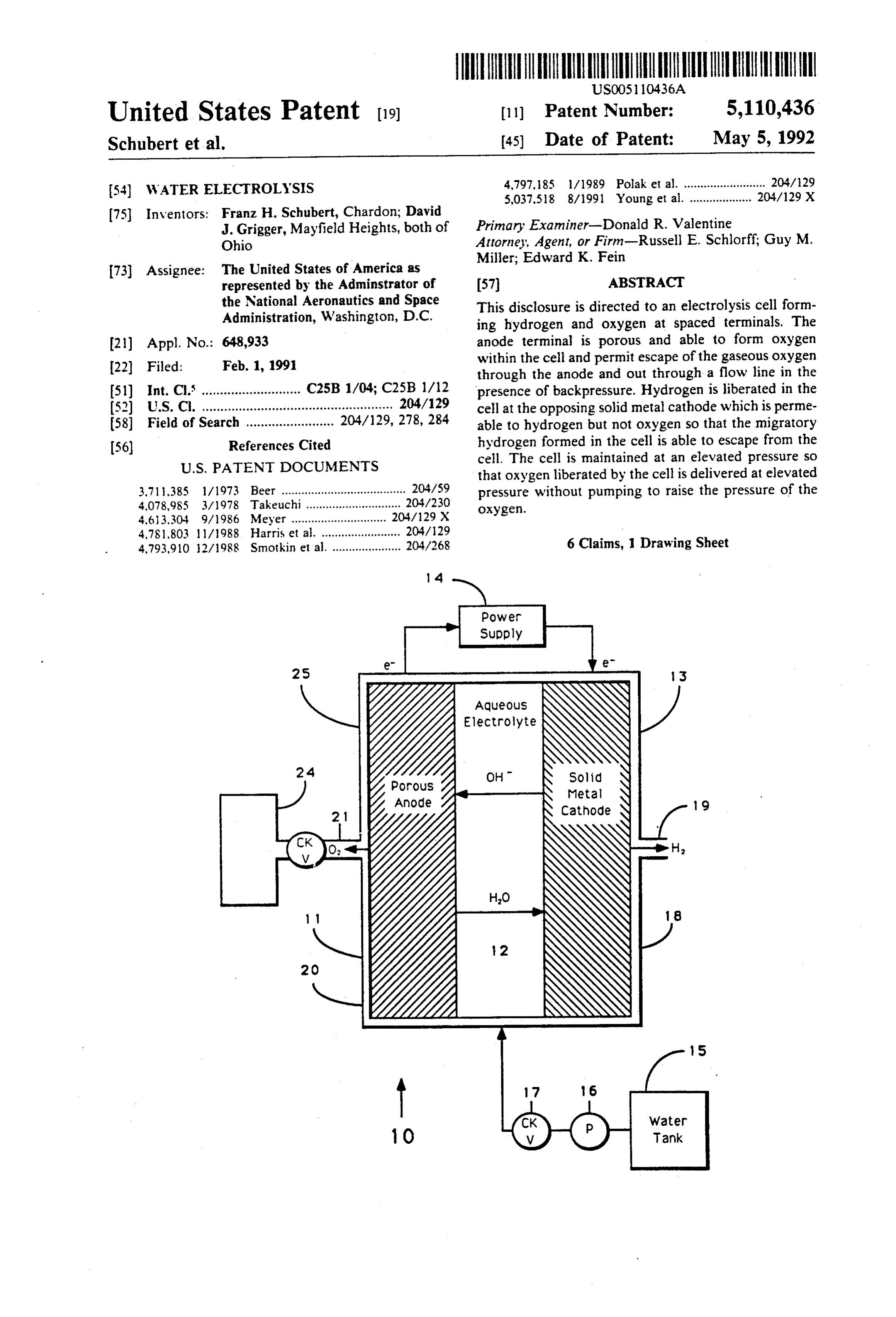
United States Patent (19) 11 Patent Number: 5,110,436 Schubert et al. (45) Date of Patent: May 5, 1992 4,797, 85 l/1989 Polak et al. ......................... 204/129 (54) WATER ELECTROLYSIS 5,037.518 8/1991 Young et al. ................... 204/129 X (75) Inventors: Franz H. Schubert, Chardon; David Primary Examiner-Donald R. Valentine J. Grigger, Mayfield Heights, both of
Ohio Attorney, Agent, or Firm-Russell E. Schlorff, Guy M. Miller; Edward K. Fein (73) Assignee: The United States of America as represented by the Adminstrator of 57 ABSTRACT the National Aeronautics and Space This disclosure is directed to an electrolysis cell form Administration, Washington, D.C. ing hydrogen and oxygen at spaced terminals. The (21) Appl. No.: 648,933 anode terminal is porous and able to form oxygen within the cell and permit escape of the gaseous oxygen 22 Filed: Feb. 1, 1991 through the anode and out through a flow line in the (51) Int. Cl. ........................... C25B 1/04; C25B 1/12 presence of backpressure. Hydrogen is liberated in the (52 U.S.C. .................................................... 204/129 cell at the opposing solid metal cathode which is perme (58) Field of Search ........................ 204/129, 278, 284 able to hydrogen but not oxygen so that the migratory (56) References Cited hydrogen formed in the cell is able to escape from the
that oxygen liberated by the cell is delivered at elevated 3,71,385 l/1973 Beer ...................................... 204/59 pressure without pumping to raise the pressure of the 4,078,985 3/1978 Takeuchi............................. 204/230 oxygen.
4,613.304 9/1986 Meyer ........... ... 204/129 X 4,781,803 l l /988 Harris et al. ........................ 204/29 4,793.910 2/1988 Smotkin et al. ..................... 204/268 6 Claims, 1 Drawing Sheet
Aqueous
Electrolyte
Solid
Page 2
Drawing sheet — no readable text.
Page 3
be maintained at a reduced or reference pressure while
WATER ELECTROLYSIS the other side is maintained at an elevated pressure. The elevated pressure enables delivery of the pressurized
ORIGIN OF THE INVENTION liberated oxygen to a pressure storage vessel without The invention described herein was made in the per 5 interposing a mechanical pump or compressor. Conve formance of work under a NASA contract, and is sub niently, the system is illustrated with a water supply and ject to the provisions of Public Law 96-517 (35 USC 202 check valve to assure delivery of the necessary amount et seq.) in which the Contractor has elected not to retain of water, and the gas which is liberated is delivered title.
10 through a check valve into a storage container. Pressure
BACKGROUND OF THE DISCLOSURE regulators can be used to regulate the various segments The Deployment of a low-Earth-orbit Space Station when the equipment is not in use.
and the onset of advanced missions will necessitate Known references include U.S. Pat. No. 3,711,385 significant requirements of metabolic oxygen (O2) for 15 which shows an electrode composed of palladium in an Extravehicular Activity (EVA). This O2 must be sup electrolytic cell. o plied at high pressure (i.e., up to 41,368 kPa (6,000 psia)) U.S. Pat. No. 4,078,985 shows a hydrogen generator to refill EVA O2 bottles. Due to the weight, volume and which is accomplished through the electrolysis of wa logistic penalties associated with high pressure O2 re ter. The apparatus consists of palladium or palladium supply and storage, alternative technologies which uti 20 alloys for the cathode material. A pipe is provided for lize on-board Space Station resources (i.e., electricity the transmission of oxygen to the anode for collection. and water) such as water electrolysis systems are prefer The object of this process is to produce a thin mem able. The Solid Metal Cathode (SMC) water electroly sis concept offers the capability to generate high pres brane dium cathode which prevents oxidation of the palla and reduces electrical consumption.
sure O directly, thus minimizing system complexity
and eliminating the need for a separate mechanical com with a palladiumPat. No. 4,781,803 shows an electrolytic cell pressor. The key problem involved in this effort in cathode. The process is used for the cluded the development of a water electrolysis concept disassociation of water into hydrogen and oxygen. which would be capable of safely and reliably generat U.S. Pat. No. 4,793,910 shows an apparatus for the ing high pressure O2. The prior technique utilized for production of H2 and O2 by electrolysis. By making use recharging the EVA O2 bottles consists of supplying 30 of multiple membranes in parallel, the inventor claims expendable O2 bottles with each mission. Upon comple to accomplish efficient photoelectrolysis. The mem tion of the mission, the O2 bottles are recovered and branes contain platinum.
recharged. The primary limitation of the prior tech U.S. Pat. No. 4,797,185 shows a fuel cell comprising nique is that the weight, volume and logistic penalties a solid electrolyte to increase the mechanical strength associated with high pressure O2 transportation and 35 storage become prohibitive for long-term missions. of the apparatus. This cell appears to be the opposite Since these missions will be feature extensive EVA, it is process of the present disclosure. essential that an alternative method be utilized. In this By contrast, the present system sets forth a structure context, the present disclosure is directed to an airborne which is capable of attaining pressures as high as 6,000 oxygen generator system and more particularly to one psi across the cell. Moreover, this is accomplished so which incorporates a mechanism capable of forming that the gas evolved has sufficient pressure drive of its oxygen in a space station in circumstances where grav own so that gas is delivered at an elevated pressure ity forces are either small or negligible. It forms oxygen. without a pump to overcome limitations on pressure in as a gas by the electrolysis of water thereby liberating downstream delivery. In this context, the system is oxygen and hydrogen. The hydrogen is liberated in 45 therefore a cell which both generates and pressurizes such a fashion that it does not pose a problem. More the oxygen which is necessary for operation of oxygen over, the oxygen generated by the system can be deliv supported equipment or personnel aboard a space craft. ered against very high back pressures, with sufficient high pressure that oxygen generation provides its own BRIEF OESCRIPTION OF THE DRAWINGS substantial pressure drive to thereby simplify the system SO So that the manner in which the above recited fea and avoid the necessity of a separate oxygen compres sor or similar equipment, reducing the weight and com tures, advantages and objects of the present invention plexity of the equipment. are attained and can be understood in detail, more par The present disclosure sets out a system wherein a ticular description of the invention, briefly summarized pair of spaced, preferably cylindrical or planar elec 55 above, may be had by reference to the embodiments trodes define an electrolysis cell. The two electrodes thereof which are illustrated in the appended drawings. are separated by a space that is filled with water, and a It is to be noted, however, that the appended draw suitable strong base placed in the water defines the ings illustrate only typical embodiments of this inven necessary electrolyte. The water can be continuously tion and are therefore not to be considered limiting of its consumed. The space between the electrodes may also scope, for the invention may admit to other equally be filled by a porous nonconductive media in which the effective embodiments.
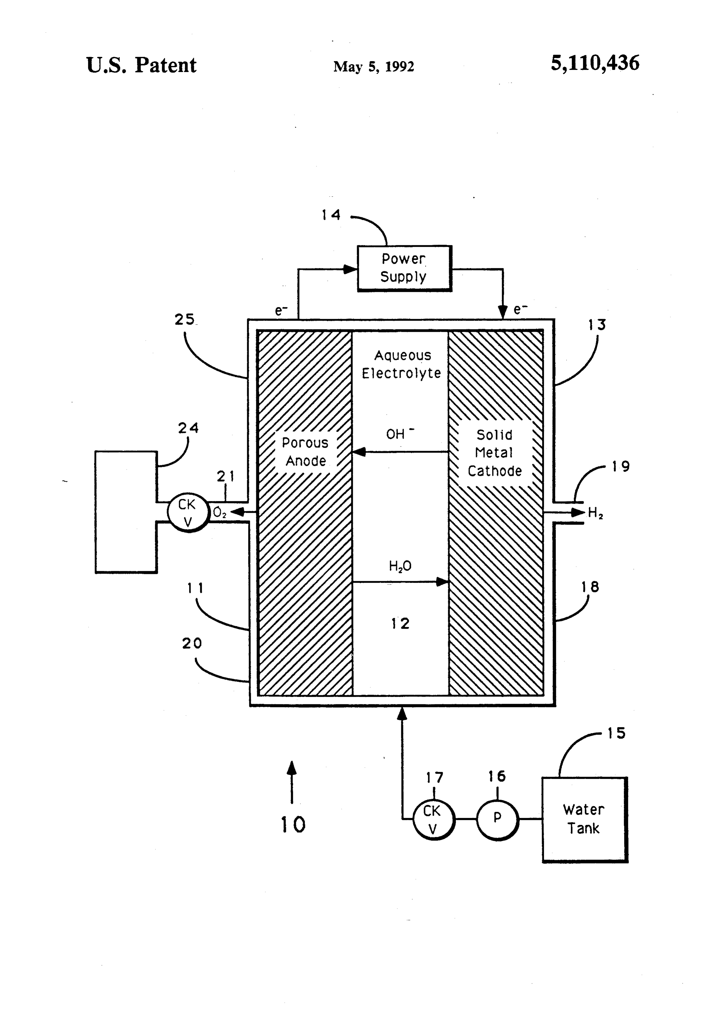
water and suitably strong base are held by capillary The single drawing is a cell having spaced anode and forces. As water is converted into constituent gases, the cathode members with an electrolyte therebetween water is replaced to keep the chamber filled. Moreover, wherein water is supplied for the electrolyte, and hy the constituent gases are liberated at the spaced elec 65 drogen and oxygen are liberated by operation of the cell trodes. One of the electrodes is porous while the other at a pressure capable of filling a large oxygen storage is a solid metal member. The solid metal electrode or terminal defines a pressure barrier so that one side can container.
Page 4
DETAILED DESCRIPTION OF THE
a crystalline lattice. This therefore enables hydrogen
PREFERRED EMBODIMENT ions to diffuse through the solid metal cathode 13 by progressive association from atom to atom within the
Attention is directed to the only view of the drawings lattice work so that hydrogen ions will diffuse across where the numeral 10 identifies the two electrodes and the thickness of the solid metal cathode 13. As individ sandwiched electrolyte therebetween which make up ual ions migrate across, they are ultimately exposed on the electrolysis cell of the present disclosure. The reac the remote surface of the cathode 13 and thereby com tion in the cell will be described first and certain fea bine to form H2 for gaseous collection. In one important tures of the surrounding and adjacent support structure sense, the cathode serves as a solid metal. In this sense, will also be given so that the operation of the system can 10 the cathode serves as a solid metal barrier which is be more readily understood. Moreover, it will be de porous to the hydrogen ions but which is not permeable scribed in the context of continuous operation so that to hydrogen or oxygen molecules as will be described. water and electricity are supplied to the cell and oxygen The solid metal member therefore enables a pressure and hydrogen gases are liberated. The process further differential to be established across the cell. Thus, the contemplates the capture of the oxygen which is accu 5 hydrogen is collected as free hydrogen gas (H2 in form) mulated in a storage vessel at high pressures, pressures at the exposed face 18 and is conducted away through as high as 6,000 psi. This cell also incorporates a gas appropriate conduits 19 for storage or other disposition. delivery system communicating from the cell to such a It is recovered at a modest pressure level. That is, the storage vessel. hydrogen flow at 19 has only a modest pressure drive The present apparatus is constructed of spaced termi 20 behind it. This pressure drive derives from the rate at nals, one being a planar porous anode and the other which hydrogen is produced by the system, and that is being a tubular solid metal cathode. Physically, they are generally a scale factor which depends on the surface spaced evenly so that a chamber is defined therebe area of the terminals in the cell 10 and the current den tween to receive the electrolyte. The two terminals are Slty.
either rectangular or circular. If circular, they can be 25 The solid metal cathode is primarily palladium. It can enclosed within a common cylindrical housing and be formed as pure palladium, but the preferred form is have been illustrated in this fashion. At one end of the to place it in an alloy with sufficient palladium content housing, hydrogen gas is liberated. At the other end of to assure permeability in the crystalline lattice for the the housing. oxygen gas is liberated. The disposition of migration of the hydrogen ions. To this end, it can be a the two gases will be described later. It is sufficient to 30 relatively simple or complex alloy. Care should be taken note for purposes of the present description that a cylin that the alloy which makes up the cathode has the ap drical housing encloses the two electrodes and the elec propriate electrochemical activity relative to the anode trolyte therebetween and is provided with a pair of for operation in the system.
terminals for convenient connection to a DC power The numeral 11 identifies the porous anode. It is supply providing a DC voltage of sufficient measure 35 porous or permeable to migration of oxygen molecules. and current flow of sufficient magnitude that the neces They migrate through the anode 11. They are recov sary amount of oxygen is generated. ered at the opposite face 20. The oxygen is enclosed Speaking in particular about the cell, the cell 10 in adjacent to that face and is conducted away from the corporates a porous anode 11 and an electrolyte region anode by a conduit 21 through a check valve 22 and 12 which is between the anode 11 and a solid metal then to a storage container 24. The storage container is cathode 3. The two terminals are connected with a preferably operated at a pressure of about 6,000 psi. power supply 14 which provides DC current through a Obviously, it will fill multiple storage containers, and pair of illustrated electrical connections. The current they can each be provided with pressure regulators or flow is directed through the illustrated terminals. Typi check valves. These have been omitted for sake of clar cally, the voltage of the power supply need only be in ity of the present disclosure. An important factor, how the range of one and one half to four volts. Typically, ever, is that the oxygen in the container 24 may be the current provided by the power supply must be suffi stored at pressures as high as 6,000 psi. This requires cient to provide an appropriate current density. Current therefore that the oxygen produced by the anode 11 densities can run as high as about 50 amps/ft or approx must be raised to a pressure of about 6,000 psi or greater imately 50 Ma/cm2. Preferably, the cell 12 is filled with 50 and which is sufficient to overcome and cause opening either potassium or sodium hydroxide in water solution, of the check valve 22 to fill the chamber or container and the water is replenished during operation. To this 24. This requires that the cell 10 be enclosed in a pres end, the system incorporates a water tank 15 which is surized housing 25. The housing must seal around the connected with a pump 16 which delivers water two terminals 11 and 13 to assure that the liberated through a check valve 17 into the cell 12. The check 55 dissimilar gases do not recombine after gas generation. valve assures that water does not leak out of the electro Moreover, the housing must provide a hermetic seal lytic cell. Thus, the pump is operated at a pressure suffi capable of withstanding working pressures at 6,000 psi ciently high to overcome any backpressure which is or greater. Accordingly, the pressure in the region of encountered during operation of the system. the anode 11 will be the back pressure which is reflected In the preferred embodiment, the cathode 13 is a solid 60 back into the system as a result of operation of the check metal member which is primarily made of palladium. valve 22 connected to the storage chamber pressure 24. During operation, hydrogen is formed in the vicinity of Assuming this to be 6,000 psi, this requires the system to the cathode 13 and it is initially deposited on the surface operate at 6,000 psi or more. Fortunately, the cathode of the palladium cathode. It typically will have an ionic 13 is a sufficiently large and thick membrane that this form which associates with palladium atoms of the solid 65 kind of pressure differential across the cathode poses no cathode to thereby form a palladium-hydride transition problem. Moreover, the high pressure acting on the complex. Structurally, the palladium is formed into the aqueous electrolyte poses no problem to its operation. solid metal structure which, at the atomic level, defines Accordingly, the pressure at the electrolyte side of the
Page 5
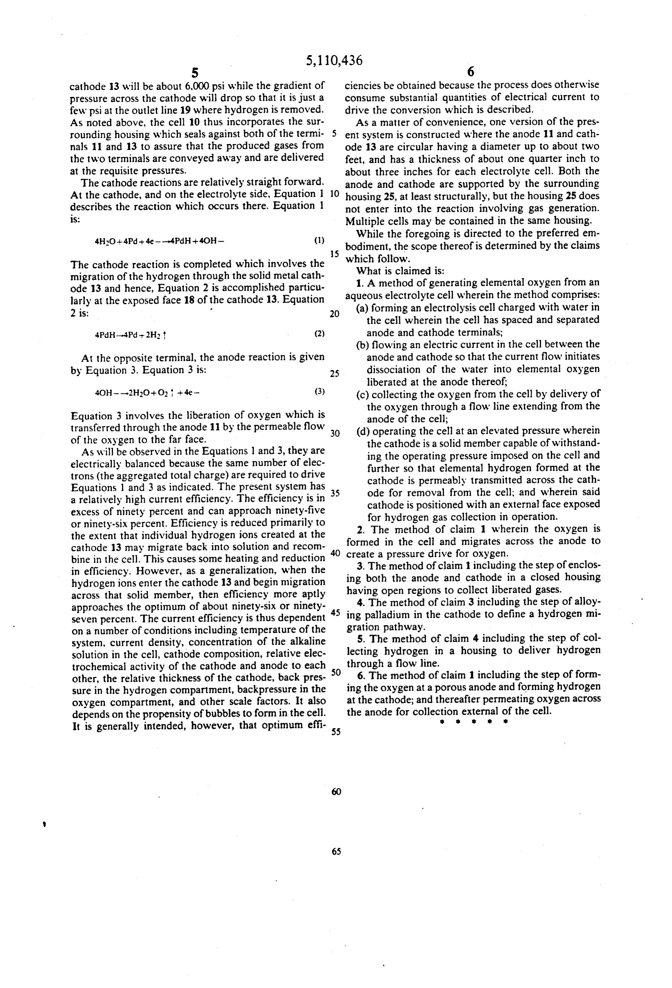
cathode 13 will be about 6,000 psi while the gradient of ciencies be obtained because the process does otherwise pressure across the cathode will drop so that it is just a consume substantial quantities of electrical current to few psi at the outlet line 19 where hydrogen is removed. drive the conversion which is described. As noted above, the cell 10 thus incorporates the sur As a matter of convenience, one version of the pres rounding housing which seals against both of the termi 5 ent system is constructed where the anode 11 and cath nals 11 and 13 to assure that the produced gases from ode 13 are circular having a diameter up to about two the two terminals are conveyed away and are delivered feet, and has a thickness of about one quarter inch to at the requisite pressures. about three inches for each electrolyte cell. Both the The cathode reactions are relatively straight forward. anode and cathode are supported by the surrounding At the cathode, and on the electrolyte side, Equation 1 10 housing 25, at least structurally, but the housing 25 does describes the reaction which occurs there. Equation 1 not enter into the reaction involving gas generation. S. Multiple cells may be contained in the same housing.
While the foregoing is directed to the preferred em
bodiment, the scope thereof is determined by the claims
The cathode reaction is completed which involves the which follow.
What is claimed is:
migration of the hydrogen through the solid metal cath 1. A method of generating elemental oxygen from an ode 13 and hence, Equation 2 is accomplished particu aqueous electrolyte cell wherein the method comprises: larly at the exposed face 18 of the cathode 13. Equation (a) forming an electrolysis cell charged with water in 2 is: w 20 the cell wherein the cell has spaced and separated 4PdH-4Pd-2H (2) anode and cathode terminals; (b) flowing an electric current in the cell between the
At the opposite terminal, the anode reaction is given anode and cathode so that the current flow initiates by Equation 3. Equation 3 is: 25 dissociation of the water into elemental oxygen liberated at the anode thereof;
4OH---2H2O+O2 -- 4e- (3) (c) collecting the oxygen from the cell by delivery of the oxygen through a flow line extending from the
Equation 3 involves the liberation of oxygen which is anode of the cell;
transferred through the anode 11 by the permeable flow 30 (d) operating the cell at an elevated pressure wherein of the oxygen to the far face. the cathode is a solid member capable of withstand As will be observed in the Equations l and 3, they are ing the operating pressure imposed on the cell and electrically balanced because the same number of elec further so that elemental hydrogen formed at the trons (the aggregated total charge) are required to drive cathode is permeably transmitted across the cath Equations 1 and 3 as indicated. The present system has 35 ode for removal from the cell; and wherein said a relatively high current efficiency. The efficiency is in cathode is positioned with an external face exposed excess of ninety percent and can approach ninety-five for hydrogen gas collection in operation. or ninety-six percent. Efficiency is reduced primarily to 2. The method of claim 1 wherein the oxygen is the extent that individual hydrogen ions created at the formed cathode 13 may migrate back into solution and recom create a inpressure the cell and migrates across the anode to drive for oxygen.
bine in the cell. This causes some heating and reduction in efficiency. However, as a generalization, when the ing both the anodeclaim 3. The method of 1 including the step of enclos and cathode in a closed housing hydrogen ions enter the cathode 13 and begin migration having open regions to collect liberated gases. across that solid member, then efficiency more aptly approaches the optimum of about ninety-six or ninety 45 ing4.palladium
The method of claim 3 including the step of alloy in the cathode to define a hydrogen mi seven percent. The current efficiency is thus dependent gration pathway.
on a number of conditions including temperature of the 5. The method of claim 4 including the step of col system, current density, concentration of the alkaline lecting solution in the cell, cathode composition, relative elec hydrogen in a housing to deliver hydrogen trochemical activity of the cathode and anode to each 50 through a flow line.
other, the relative thickness of the cathode, back pres ing6.theThe method of claim 1 including the step of form oxygen at a porous anode and forming hydrogen sure in the hydrogen compartment, backpressure in the oxygen compartment, and other scale factors. It also at the cathode; and thereafter permeating oxygen across depends on the propensity of bubbles to form in the cell. the anode for collection external of s the cell.
It is generally intended, however, that optimum effi 55
Provenance
- Collection
- Patents citing this work
- Original assignee
- National Aeronautics and Space Administration NASA
- Pages
- 5
- Method
- pdftotext (the PDF's own text layer) + pdftoppm 300dpi page scans
- Patent office record
- patents.google.com →
- Source
- Google Patents citing-documents table
- Inventors
- Franz H. Schubert; David J. Grigger; National Aeronautics and Space Administration NASA
- Published
- 1992-05-05
- Transcribed from
- patentimages.storage.googleapis.com →