patent · US2291534
Method of making refractories
28 July 1942
Page 1
Drawing sheet — no readable text.
Page 2
Drawing sheet — no readable text.
Page 3
Drawing sheet — no readable text.
Page 4
Drawing sheet — no readable text.
Page 5
other advantages of production in accordance which the maximum temperature obviously will with my process also result. be less; moreover, with the arc, the same has the According to either phase of the process, the effect of blasting and disrupting the refractory refractory to be treated is first broken up into against which it impinges. Nor could an electric small pieces or pulverized to a coarse mesh. If current be caused to flow through the mass of different refractories are used, they are then the majority of refractories which I employ as carefully mixed together. One of those refrac they are not good conductors of the electric cur tories may be a clay which has a substantially rent. With my process, the application of heat lower melting point, than the others, so that it is.smooth and non-disruptive and permits smooth quickly melts and flows down in and around the 10 gradual heating in the mass of refractory being interstices in the particles thus transmitting the treated.
heat to them, exposing them to receive more of Because of the high temperatures used with my the radiant heat, and holding the particles to process, it is important to provide a means such gether by adhesion. . Further, the refractory com that the refractory in the flnal heat treatments ponent in this process which has the lower melt of commercial forms, shall not melt down or de ing point appears to exert a peculiar influence on stroy the support, or enclosing table, furnace, those components having the higher melting ?rucible or other equipment, because if that ?? points, and tends to reduce such melting points curred, the process would be inoperative. I per to accelerate fusion of the latter to produce the ceived that a solution for this difficulty is pro relatively homogeneous physical mixture and 20 vided by reason of the fact that the speed of ?et, when this mixture has been produced and penetration of solar heat on noncombustible ma has solidified, its melting point has been found terials is limited even at high temperatures when to be substantially higher than that which was applied to refractories, which may be built up in needed to first produce it. large mass of desired size and form so as to be Hence, in this process, the refractory product 25 self-sustaining by frictional or adhesive engage may be pre-heat treated two or more times to ment of the particles with each other according secure higher fusion points by applying the solar to melting points of different elements used, pre rays to melt the elements to a formless mass. liminary to final fusion. Here the nondisruptive When the desired higher melting points have been quality of the concentrated solar beam is of the produced, the mass may be crushed to any de 30 essence in the invention.
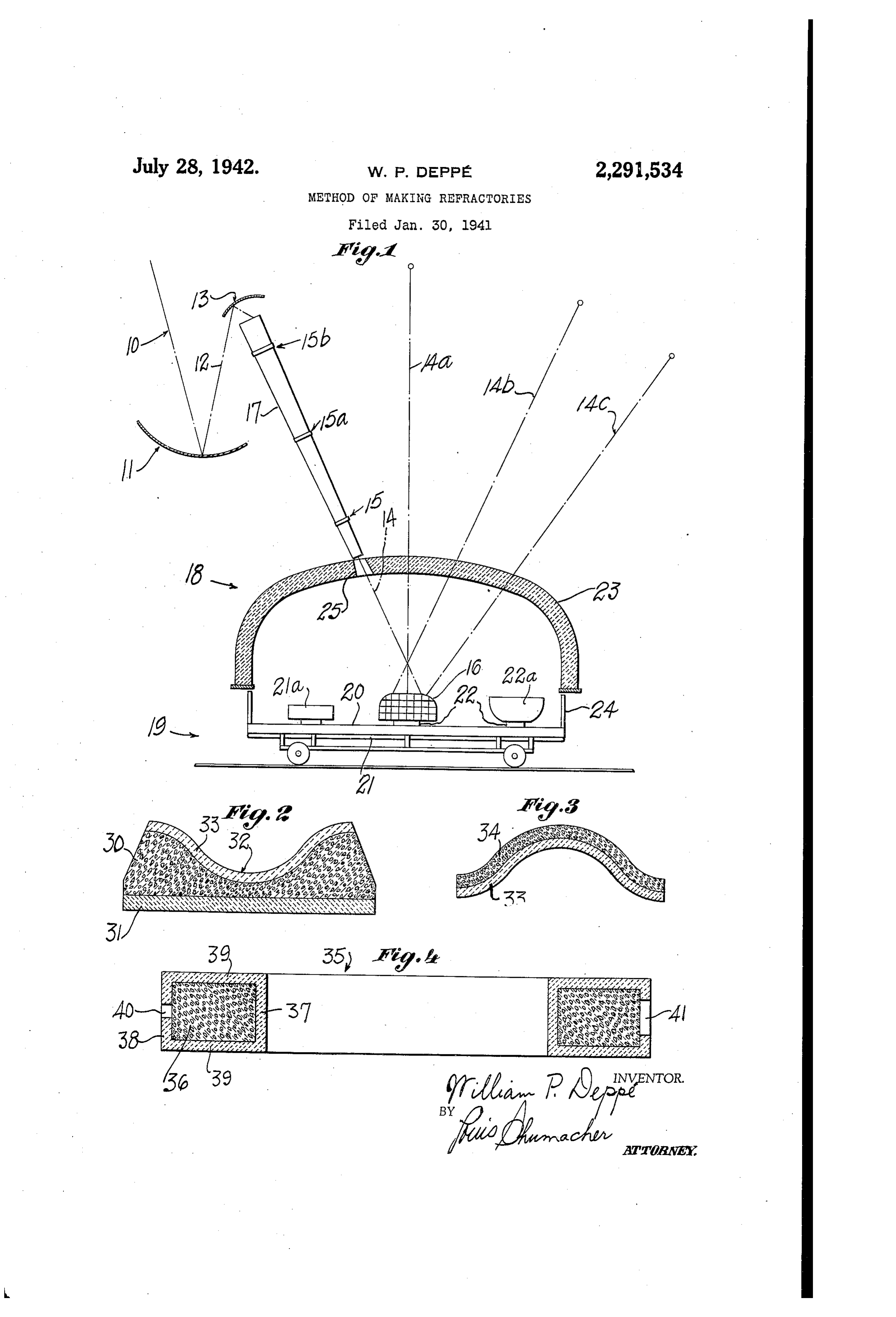
sirable fineness by any suitable mechanical To facilitate the control Of Solar ray heat and means, then preparing commercial shapes for its application over all of the refractory element various purposes and binders used, such as fire being treated, as shown at 16 in Fig. 1 in attached clays and cement for final heat treatments. drawing, a portion of the refractory top of moV In effecting the process according to either of able wagon on which 16 rests, may be constructed the above mentioned phases, the heat may be ap so as to revolve either by manual means or by plied over a period of several hours, or interInit suitable mechanical means, thus applying the so tently on several days, with intervals of time dur lar rays intermittently at any given point. The ing which the new refractory maSS becomes shifting of the wagon also alters the points in ele stabilized by internal pressure set up in cooling 40 ment 16 on which the solar ray heat is applied. to produce a Superior molecular Structure. ThuS To more clearly explain this feature of the the refractory mass may be permitted to cool dur process, reference is had to FigS. 2 and 3, show ing the night at a rate sufficiently slow to avoid ing the method of making a crucible suitable for ?racking thereof. In either event, the tempera being heated by gaseous fuel burning under cata ture applied during successive days or periods 45 lytic or surface combustion conditions in 30 in may be successively higher; this may be prac Fig. 2, according to the invention. In Fig. 2 ? ticed, however, even if there is no time intervals mass 30 of finely divided carefully mixed refrac of cooling and heating, so that the efficiency of tory properly heat-treated, has been provided, on heat application in stages, is at a maximum, with a suitably shaped or plane refractory plate"31, the the temperatures varying according to the refrac upper part of the mass being shaped concave at tory components that are to be successively fused; 32 to correspond to the inside of the crucible and thus the new refractory mass attains its final which has previously been heat-treated. The successive applications of heat, as by concen condition in a graduated manner, and with an in creasing rate of heat absorption. As the process trated solar beams at 14, 14?, 14b and 14?, in Fig. continues, internal pressure due to heat in the 55 1, have fused the upper surface portion into a refractory mass increases, which promotes the layer 33. This layer 33 may be allowed to cool beneficial characteristics sought and aids in pro slowly for a period of time, and again subjected ducing the fine and even mechanical texture of to the process to fuse the mass 34 together and "microscopic character as distinguished from a to the layer 33 to form with the latter a substan rough mechanical mixture such as readily ob tially homogeneous physical mass forming a Served under the microscope in the case of allo? 60 ?rucible of desired thickness and strength. In steels. During the different heat treatments the the same manner, additional layers may be added sun ray reflecting means should be kept clean, for further thickness.
and such-surfaces dusted and polished. * Suitable inlets and outlets must be provided in The process is possible only because solar heat, 65 the mass 30 for the combustible gases to be used gathered and concentrated in a suitable manner therein under surface combustion conditions. is controllable and smoothly applied and affords With the process indicated in Figs. 2 and 3, it higher temperatures in the work than any here will be seem that the refractory. mass actually tofore available, except in combustion of explosive forms a furnace portion in that it is the primary materials, or in certain purely laboratory experi 70 seat of heat application, and while a portion of mentS that are too costly and limited in charac the refractory mass is being fused, another por ter for commercial use. By way of distinction, tion thereof supports the fused part thus insulat the electric arc may be used to produce tempera ing it from the car floor or bottom of the main tures of 6000 degrees F., but this is the tempera furnace chamber and rendering the refractory ture in the arc itself, and not in the work in 75 Ima88 in which the fusion occurs self-sustaining.
Page 6
In Fig. 4 is shown an arcuate or ring shaped mixing refractory materials, moulding the same surface combustion block 35 having an internal in shape like the form of the body to be produced, mass consisting of small lumps or broken pieces gathering and concentrating solar energy upon of high temperature refractory 36, produced as the surface of the moulded form, and maintain hereinbefore described. The Spaces therebe 5 ing the latter thus heated until surface portions tween provide the irregular passages for the melt and fuse together into a substantially homo flame according to this catalytic combustion. geneously mixed condition while being supported These spaces must be sufficient to prevent scor b? unmelted refractory underneath, then slowly ing of the refractory by excessive gas velocity. cooling the body produced. . . Enclosing the refractory 36 is a shell comprising 10 5. The method of producing high temperature inner and outer walls 31, 38 and side walls 39. refractory materials, including pulverizing and Formed in the wall 38 is an inlet 40 and an outlet mixing together different high temperature re 41, the former for the gas-air mixture, the latter fractory materials, gathering and concentrating for the exhaust gases. The shell 31, 38, 39 may solar energy upon the pulverulent mass and caus have been formed with a component of cement 15 ing fusion thereof into a body, which is substan and clay for easy molding and thoroughly fused tially microscopically uniform upon solidification, according to my process, after bcing applied at least one of said refractory materials having around the refractory mass 36 as shown. Thus a melting point substantially lower than that of the Walls become fused to some of the outer and the other materials, in order to rapidiy melt and innermost lumps 36 to permit the flame travel 20 flow in and between the pulverulent particles, to in immediate proximity to the walls. If desired, rapidly conduct heat to those particles which the four Walls may be separately constructed have not yet softened by reason of higher melt;- and fused together without using a binder; and ing points. * 8 then such walls may be placed around the re 6. The process of increasing the melting break fractory mass 36 and the walls fused together 25 down point of a refractory mass, including pro along the four corners, affording a maximum Viding such a refractory mass consisting of re internal capacity for gaseous flow and an extreme fractory substances having different melting durability in use. points and being in closely intermixed condition, It is obvious that refractory articles such as applying concentrated solar heat to said mass indicated at 2?a and 22a, may be preheated with 30 in successive stages separated by substantial time out solar rays being put on same, while the re intervals at temperatures to permit physical and fractory article I6 is being treated by applica chemical changes in the elements in the refrac tion of the solar ray heat which in turn, heats tory mass, and with said concentration being up the ambient under the roof section. sufficient to produce increasing high temperatures It is understood that I am not limited to any 35 for the progressive melting and fusing of the re particular design or proportions of apparatus and fractory substances during the process. elements in products for the purposes cited here 7. The process according to claim 6, wherein in, nor limited to the exact temperatures men said refractory mass is cooled during the said tioned herein, in refractories or combinations time interVals.
thereof with other minerals, for the purposes 40 8. The process according to claim 6, wherein named. .. . the successive stages are performed at succes It will be obvious to those skilled in the refrac sively increasing temperatures. tory art, that the illustrative examples described 9. The process according to claim 6, wherein herein, will show how this new process may be the said mass is heated during said intervals at applied in the production of higher temperature 45 temperatures substantially lower than the sald refractory elements for the purposes outlined on melting temperatures to bake the mass. page 3 herein. * ? 10. The method of producing high temperature I claim: » . refractory materials including concentrating a 1. The method of producing high temperature beam of radiant energy which is capable of di refractory materials including concentrating a 50) rectly generating heat in the surface portion of beam of radiant energy.which is uapable of di a refractory mass and causing said heat to melt rectly generating heat in the surface portion of the refractory into a mass which is a substan a refractory mass and causing said heat to melt tially homogeneous mixture upon solidification, and fuse the refractory into a mass which is a ?rushing the mass so produced, mixing together substantially homogeneous mixture upon solidi 56 the pulverized mass into commercial forms with fdcation. . ?. binder elements, and again heat-treating the re 2. The method of producing high temperature sultant mass in the same manner to assure a refractory materials, including. gathering and mixture which is substantially homogene??s for concentrating solar energy upon a refractory substantial depth.
mass and causing the elements therein to be 60 11. The method of producing high temperature melted and fused into a uniform mass by the refractory materials for purposes described, in heat generated, impervious to molten metals and cluding concentrating a, beam of radiant solar hot gases up to 6000 deg. F. and above. energy which is capable of generating heat in 3. The method of producing high temperature the surface portion of a refractory mass and refractory materials, including pulverizing and 65 causing said heat to-spread in the mass at tem mixing together different high temperature re peratures capable of causing physical and chem fractory materials, gathering and concentrating ical changes in the refractory elements used, and solar energy upon the pulverulent mass and caus to melt and fuse the refractory mixture into a ing fusion of at least a surface portion thereof mass which is substantially homogeneous upon into a body which is microscopically uniform 70 Solidification and capable of resisting slagging by upon solidification. molten metals or breaking down by hot gases. 4. The method of producing high temperature retractorybodles, which includes pulverizing and WILLIAM P. DEPPé.
Provenance
- Collection
- Cited prior art
- Original PDF
- patentimages.storage.googleapis.com →
- Filed
- 1941-01-30
- Pages
- 6
- Method
- pdftotext (the PDF's own text layer) + pdftoppm 300dpi page scans
- Source
- Google Patents bibliographic record
- Granted
- 1942-07-28
- Inventors
- William P Deppe
- Transcribed from
- patentimages.storage.googleapis.com →