patent · US2109963
Apparatus for supplying gas to internal combustion engines
1 March 1938
Page 1 — bibliographic record
; APPARATUS FOR SUPPLYING GAS TO INTERNAL COMBUSTION ENGINES
Filed Aug. 15, 1936. 2 Sheets—Sheet 1
Inventor
A gs Alvin Hitruse
Los oy GDomoe Uofehion,
Nyman Bh "Aiemey i
Page 2
: APPARATUS FOR SUPPLYING GAS. TO INTERNAL COMBUSTION ENGINES Filed Aug. 13, 1936 2 Sheets-Sheet 2
7 OOF F
BAY
SSESssSsssss
: z ‘-- sO Inventor 16 . Alvin HH. Mruse
| ® (Lhnce ion on
Page 3
Patented Mar. 1, 1938
UNITED STATES
PATENT OFFICE
APPARATUS FOR SUPPLYING GAS TO IN-
TERNAL COMBUSTION ENGINES
Alvin H. Kruse, Sunburst, Mont.
Application August 13, 1936, Serial No. 95,903
1 Claim.
This invention relates to fuel control mechanisms for internal combustion engines and more particularly to a device for use in supplying natural gas to such type of engines.
Briefly the invention consists in the provision of an improved valve which may be applied either directly to the air intake of a carbureter or to the intake manifold of an internal combustion engine, and which valve is adapted to operate in response to suction created by the internal combustion engine for controlling the supply of a mixture of natural gas and air to the internal combustion engine.
The invention together with its objects and advantages will be best understood from a study of the following description taken in connection with the accompanying drawings, wherein:—
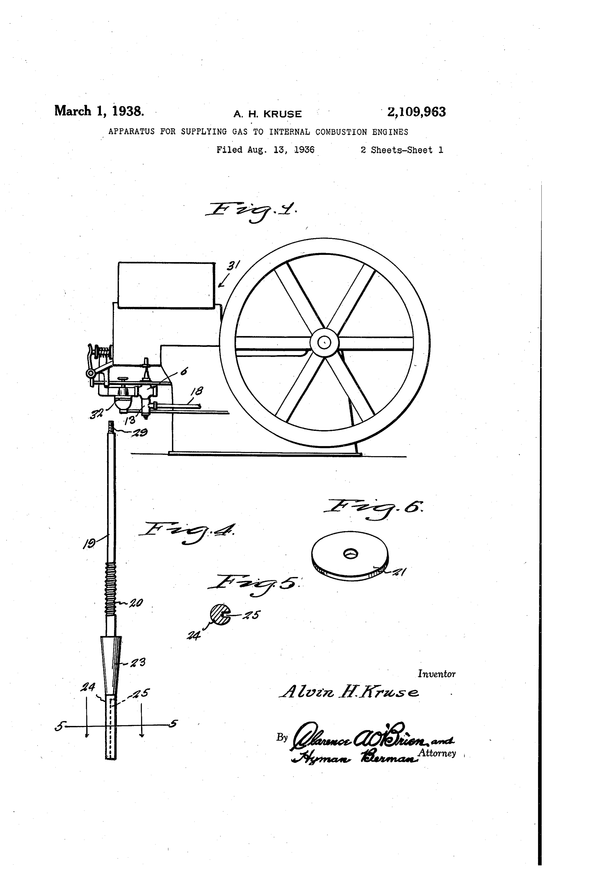
Figure 1 is side elevational view, illustrating the application of the invention to an internal combustion engine ofthe stationary type.
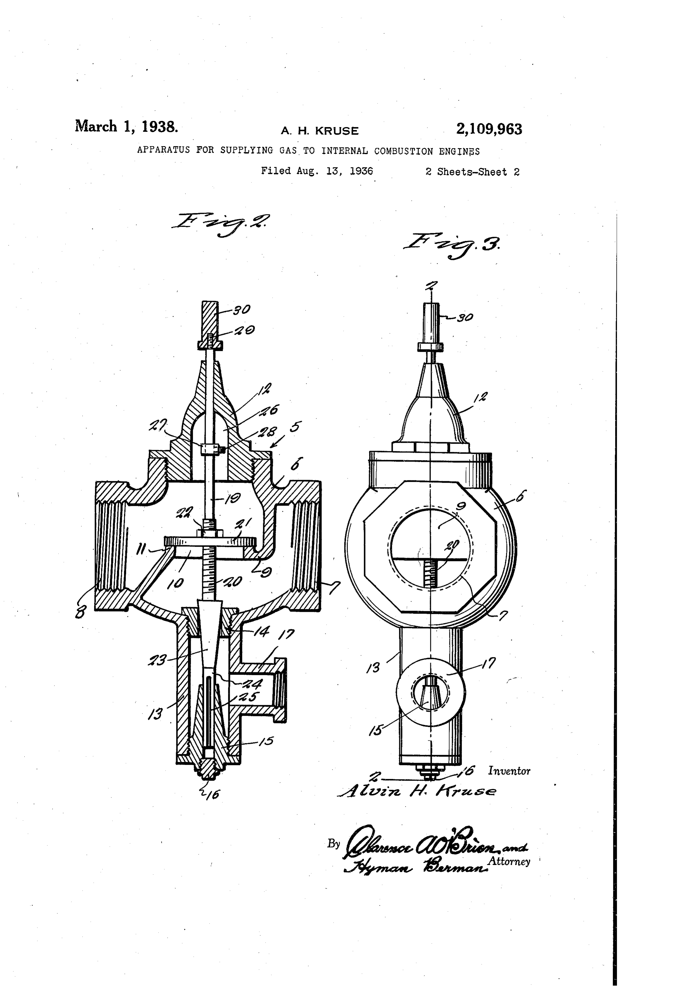
Fig. 2'is an enlarged sectional view taken substantially on line 2—2 of. Fig. 3.
Fig. 3 is an elevational view of the valve forming the salient feature of the present invention.
‘Fig. 4 is an elevational view of a valve stem.
Fig. 5 is a sectional view taken substantially on the line 5—5 of Fig. 4, and
Fig. 6 is a perspective view of a valve.
Referring to the drawings by reference numerals, it will be seen that the gas supply device, embodying the features of the present invention is indicated generally by the reference numeral 5. In a preferred embodiment thereof, the de-
“ vice 5 comprises a casing 6 somewhat similar to
a globe valve casing having at one side thereof an internally threaded intake neck 7, and at a relatively opposite side thereof an internally threaded outlet neck 8. -
Interiorly the casing 6 is provided with @ partition 9 having an apertured central section providing a passage 10 communicating the portions of the valve casing 6 at opposite sides of the par-
- tition, and presenting about the Passage 10 an
annular valve seat tf. .
For the top of the valve there is also provided a bonnet {2 that has screw threaded connection with the valve casing 6.
Also the valve casing 6 has integral with and extending downwardly from the bottom thereof, a tubular extension [3. Threaded into the extension {3 where it joins with the casing 6 is a removable valve seat {4.
Threaded into the lower end of the extension | 3 is a valve stem guide 15, the bore of which at the lower end of the guide is closed by a plug (6,
The extension-13 also has an internally threaded lateral inlet neck 47 to which is coupled one end of a natural gas conduit 18 leading from any suitable source of supply as suggested in Fig. 1.
Working through the bonnet 42 is the upper end of an elongated valve stem 19. Stem 19 has an intermediate threaded section 20 with which . is associated the disk valve 2{ that is secured at the desired adjustment on the stem 20 through the medium of a neck 22.
Also below the threaded section 20, stem {9 is provided with a substantially conical valve core 23 which works through and cooperates with the valve seat 14 for controlling communication between the casing 6 of the valve and the tubular extension {3.
At its smallest end, the valve core 23 merges into the cylindrical extension 24 of the stem 19, and this extension 24 has a snug sliding fit within the stem guide 15, - Extension 24 is: also provided with a slot 25 which serves as an escape for air from the guide {5 so as to permit the stem 19 to move downwardly for Proper seating of the valves 2{ and 23.
The bonnet 12 is hollowed out as at 26 to accommodate a collar 27 adjustable on the stem {9 and secured at the desired adjustment through the medium of a set screw 28. Collar 29 is suitably adjusted on the stem 9 to limit the upward movement of the stem 9.
Also at its upper end, the stem (9 is provided with a threaded pin 29 to accommodate a suitably threaded weight 30. Various sizes of weights 30 may be employed, as may be found desirable. ° . :
In Fig. 1 is illustrated the application of the invention to an internal combustion engine 3f of the stationary type. The engine 31! is equipped with, among other parts, a conventional carbureter 32. In applying the invention to such an engine, I have illustrated the valve casing 6 of the device 5 as having its outlet end 8 screw threadedly engaged with the air intake of the carbureter 32.
The operation of the device may be briefly described as follows:—
When the device is in operation, a vacuum in the valve casing 6 above the partition 9 is produced by engine suction. Under such conditions valve 24 will move upwardly off of its seat ii, stem {9 rising to also unseat the valve core 23. Air from the atmosphere enters the casing 6 while the fuel from the source of supply passes into the extension 13 and through the valve seat {4 into the casing to mix with the air entering
Page 4
through the ports 1. The mixture of gas and air flows through the port 10 to the opposite side of the partition 9 and from the casing 6 through the outlet 8 into the carbureter, passing of course from the carbureter into the intake manifold of the internal combustion engine.
It is obvious that valves 21 and 23 will remain unseated as long as there is any suction, and as the speed of the engine increases, stem {9 will rise for further unseating the valves 21 and 23, the limit of the upward movement of the stem [9 being determined by the position of adjustment of the collar 21. Thus it will be seen that the supply of natural gas and air to the engine will be regulated in consonance with the speed of the engine, with the result that the exact proportions of air and gas suitable for efficient operation of an internal combustion engine using natural gas as a fuel are easily obtained. .
Having thus described the invention, what is claimed as new is:— ; .
An air and gas mixing device comprising. a
casing having a partition therein and provided .
at one side with a mixing chamber having a gas inlet and an air intake and provided on the opposite side with a suction chamber having a fuel
gas and air mixture outlet, said partition being also provided with a port therethrough in line with the gas inlet and with the valve seat surrounding said port on the suction side of the casing, a valve stem extending through the said port and through the said gas inlet of the said casing, a suction valve on said stem engageable with said seat, a gas chamber in communication with the gas inlet of the casing and having means for connection with the source of gas supply, a valve seating member in said gas inlet, a valve integral with said stem and engaging the valve seating member for shutting off communication between the casing and the said gas chamber, said last mentioned valve being unseated by corresponding movement of the suction valve, weight means on said stem for holding said valve seated in re-
sponse to the defect of gravity, a plug threaded _
in one end of the gas chamber and having a bore therethrough closed at its outer end, said bore constituting a guide for one end of the valve stem, said end of the valve stem having a split extending longitudinally therein and terminating beyond the guide to provide an air escape for the guide.
ALVIN H. KRUSE.
Provenance
- Collection
- Cited prior art
- Original PDF
- patentimages.storage.googleapis.com →
- Filed
- 1936-08-13
- Pages
- 4
- Method
- pdftoppm 300dpi + tesseract 5 (eng)
- Source
- Google Patents bibliographic record
- Granted
- 1938-03-01
- Inventors
- Alvin H Kruse
- Transcribed from
- patentimages.storage.googleapis.com →