patent · US20110253128A1
Solar heat exchanger
20 October 2011
Page 1 — bibliographic record
(19) United States (12) Patent Application Publication (10) Pub. No.: US 2011/0253128A1
Nakamura (43) Pub. Date: Oct. 20, 2011 (54) SOLAR HEAT EXCHANGER Publication Classification (75) Inventor: Katsushige Nakamura, Tokyo (JP) (51) FEao (2006.01) (73) Assignee: MITAKA KOHK CO.,LTD., F24, 2/48 (2006.01) Tokyo (JP) F24, 2/04 (2006.01)
(52) U.S. Cl. .......................... 126/645; 126/679; 126/610 (22) PCT Filed: Dec. 24, 2009 (57) ABSTRACT (86). PCT No.: PCT/UP2009/071427 A light receiving plate floating on the Surface of tin, i.e., a low-melting-point heating medium and receiving Solar
S371 (c)(1), beams is made of solid carbon material entirely coated with a (2), (4) Date: Jun. 23, 2011 silicon carbide film. Due to the silicon carbide film, the Sur face of the light receiving plate is black to realize a high (30) Foreign Application Priority Data absorption ratio of the solar beams. In addition, the light receiving plate is made of the silicon carbide film at least at
Dec. 24, 2008 (JP) ................................. 2008-327647 the surface thereof, to demonstrate excellent heat resistance.
Page 2
Drawing sheet — no readable text.
Page 3
Drawing sheet — no readable text.
Page 4
Drawing sheet — no readable text.
Page 5
Drawing sheet — no readable text.
Page 6
US 2011/0253 1 28 A1 Oct. 20, 2011
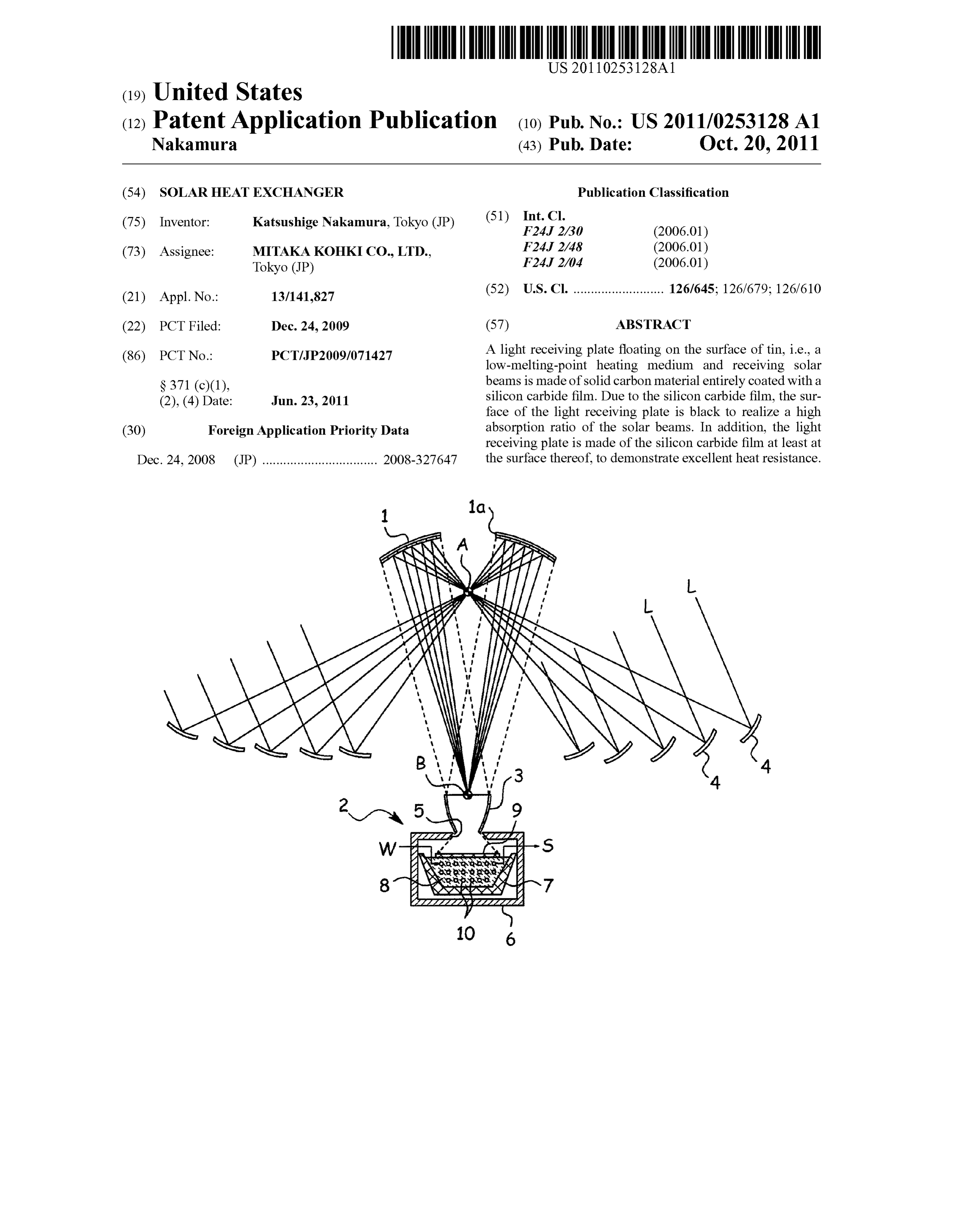
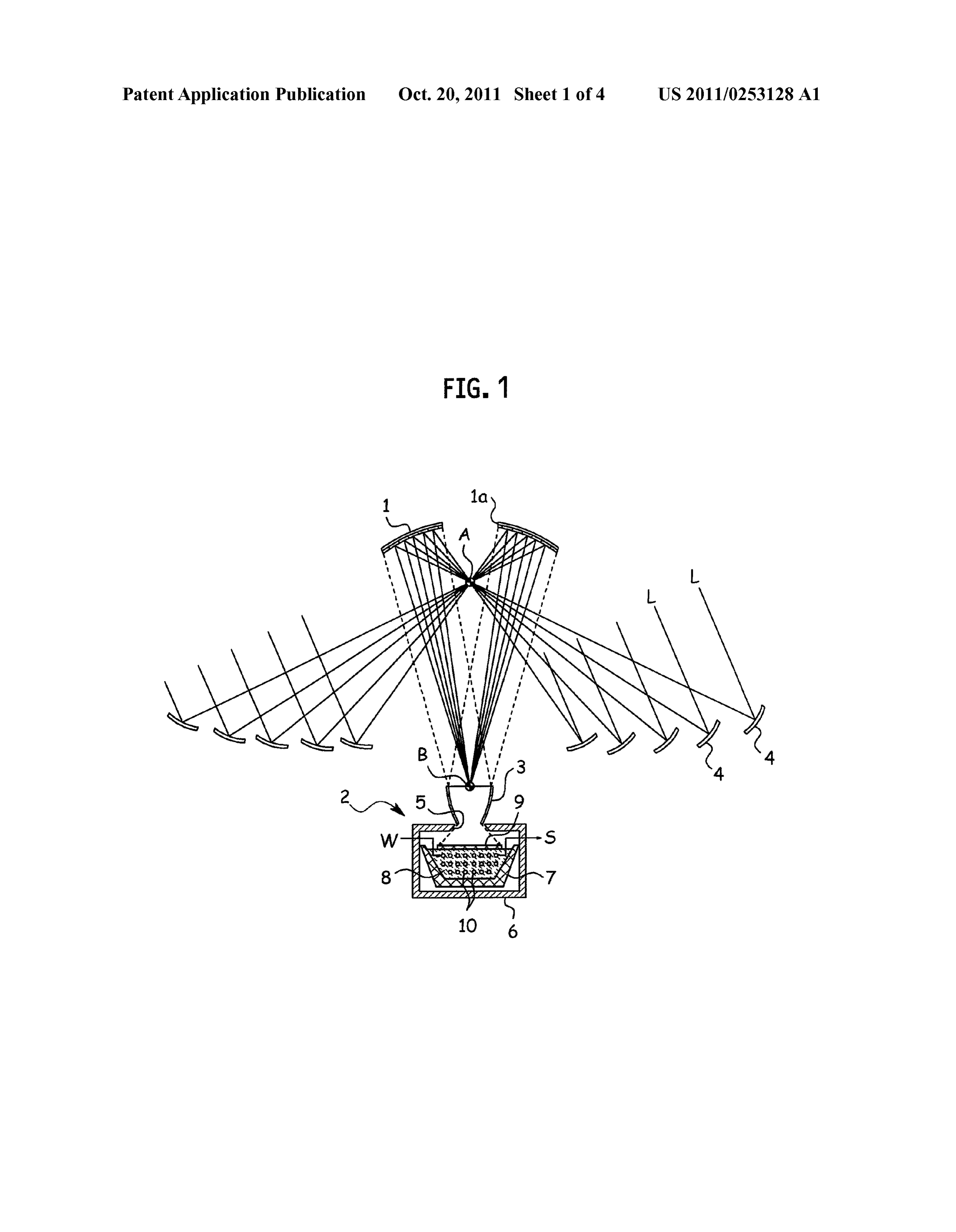
SOLAR HEAT EXCHANGER Support tower (not illustrated) at a predetermined height in a downwardly oriented State. A circular opening 1a is formed at
TECHNICAL FIELD the center of the elliptic mirror 1. The elliptic mirror 1 has a 0001. The present invention relates to a solar heat mirror Surface that is defined as a part of an ellipsoid, and exchanger. under the same, there are a first focus A and a second focus B. Under the elliptic mirror 1, a heat exchanger 2 is arranged to
BACKGROUND TECHNOLOGY convert Solar beams Linto heatenergy. At an upperpart of the heat exchanger 2, there is a collector mirror 3 substantially 0002. There is known a beam-down solar concentration having a tapered cylindrical shape. On the ground around the apparatus that reflects, with a plurality of reflection mirrors heat exchanger 2, many heliostats 4 are arranged to Surround called heliostats, Solar beams toward a center mirror Sup the elliptic mirror 1.
ported at the top of a high tower and concentrates downwardly 0013 Each of the heliostats 4 is controlled by a sensor reflected solar beams from the center mirror on a point to system (not illustrated) so that solar beams L reflected by the obtain heat (for example, Japanese Unexamined Patent heliostat 4 may pass through the first focus A. Once the Solar Application Publication No. H11-1 19105). beams L reflected by the heliostats 4 pass through the first 0003. In the case of the beam-down structure of this sort, focus A, the solar beams are downwardly reflected by the the downwardly reflected solar beams directly heat, for elliptic mirror 1, are always collected at the second focus B, example, a metallic coil to change water circulated inside the and reach the heat exchanger 2 through the collector mirror 3. coil into vapor. 0014. The heat exchanger 2 has a box 6that has an opening
OUTLINE OF INVENTION
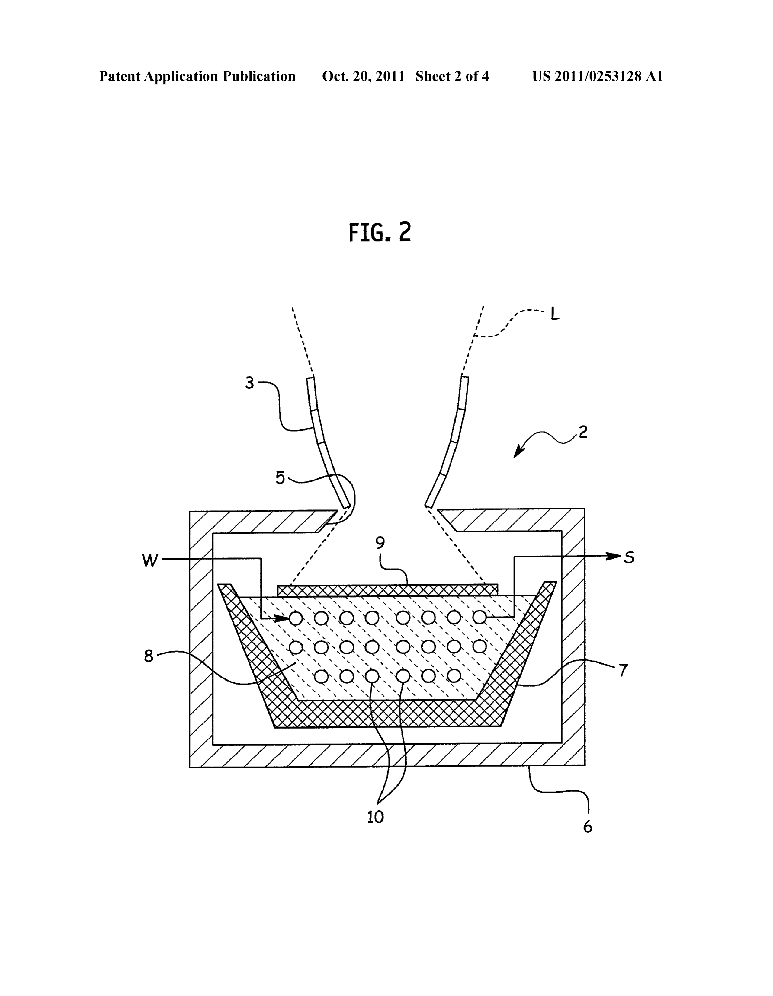
5 at the top thereof and is made of autoclaved lightweight concrete (ALC). The collector mirror 3 is arranged at the 0004. According to the structure of the related art of opening 5. In the box 6, there is a heat-resistant container 7 directly heating the metallic coil with solar beams, however, made of black carbon material. Inside the heat-resistant con a metallic color of the surface of the metallic coil reflects solar tainer 7, there is held tin 8 serving as a low-melting-point beams to hinder efficient heat exchange. The surface of the heating medium. On the Surface of the tin 8, a light receiving metallic coil is heated with solar beams to very high tempera plate 9 made of black carbon material floats. In the tin 8, aheat tures, and therefore, a black coating, should it be applied to exchanging pipe 10 meanders. In the pipe 10, water W Serving the surface, will easily peel off. as a heat conducting medium is Supplied from one side and vapor S is discharged from the other side.
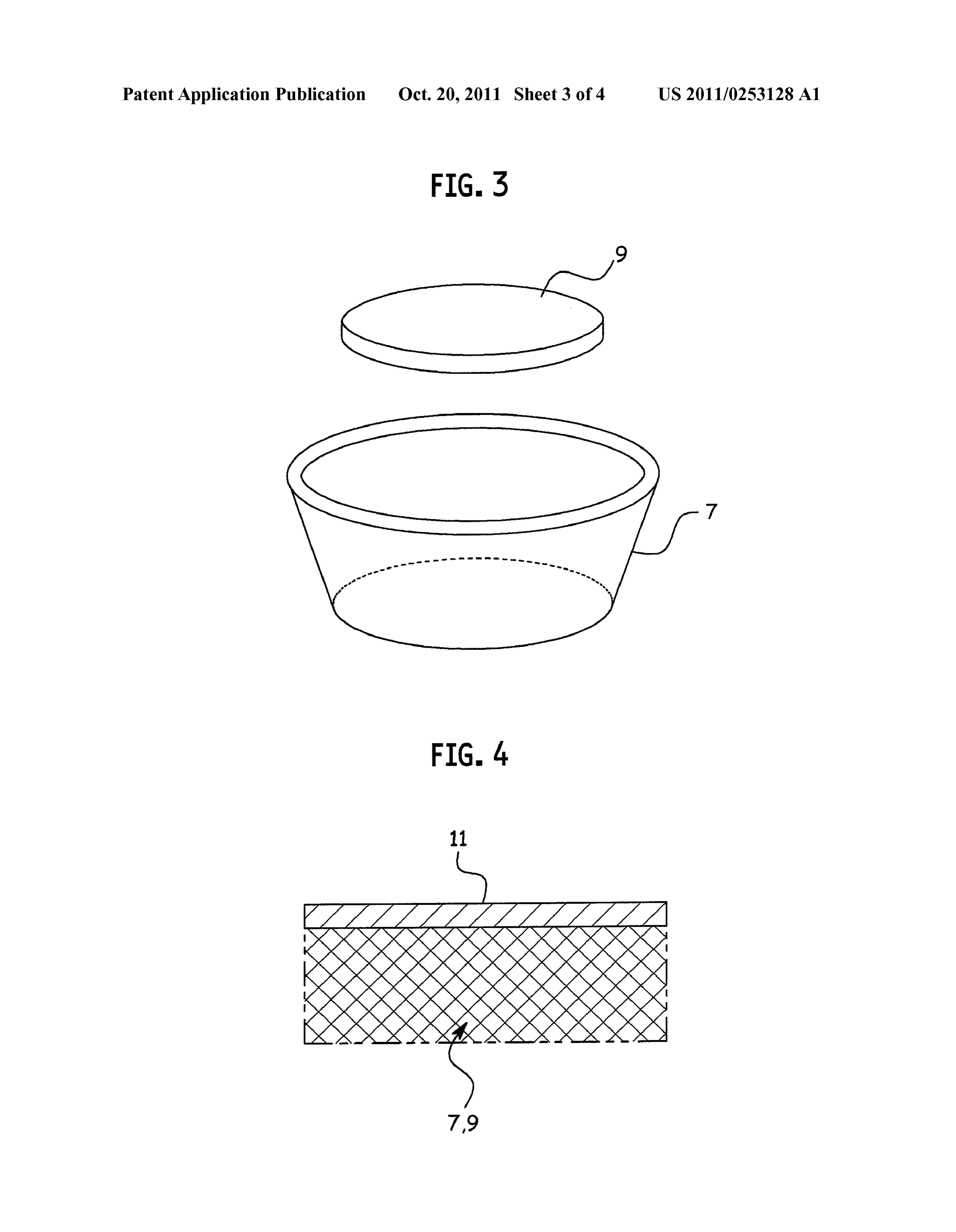
MEANS TO SOLVE THE PROBLEMS 0015 The heat-resistant container 7 has an open top shape having a tapered side face that upwardly widens from a cir 0005. In consideration of the related art, the present inven cular bottom. The black carbon material that forms the heat tion provides a Solar heat exchanger capable of efficiently resistant container 7 is entirely coated with a silicon carbide converting Solar beams into heat. (SiC) film 11.
0006. According to a technical aspect of the present inven 0016. The light receiving plate 9 floating on the surface of tion, a structure includes a top-open, heat-resistant container the tin 8 has a disk shape and is made of black carbon material that holds a low-melting-point heating medium and a light entirely coated with a silicon carbide film 11. The silicon receiving plate that is Supported on and is in contact with the carbide film 11 itself is black, and therefore, the solar beams Surface of the low-melting-point heating medium. It is char L collected by the collector mirror 3 and received by the light acterized in that the light receiving plate is made of Solid receiving plate 9 are absorbed at a high absorption ratio silicon carbide, or solid carbon material entirely coated with (about 95%) and are changed into heat. a silicon carbide film.
0017. The heat changed by the light receiving plate 9 is conducted to the tin 8 that becomes molten when the tem
BRIEF DESCRIPTION OF DRAWINGS
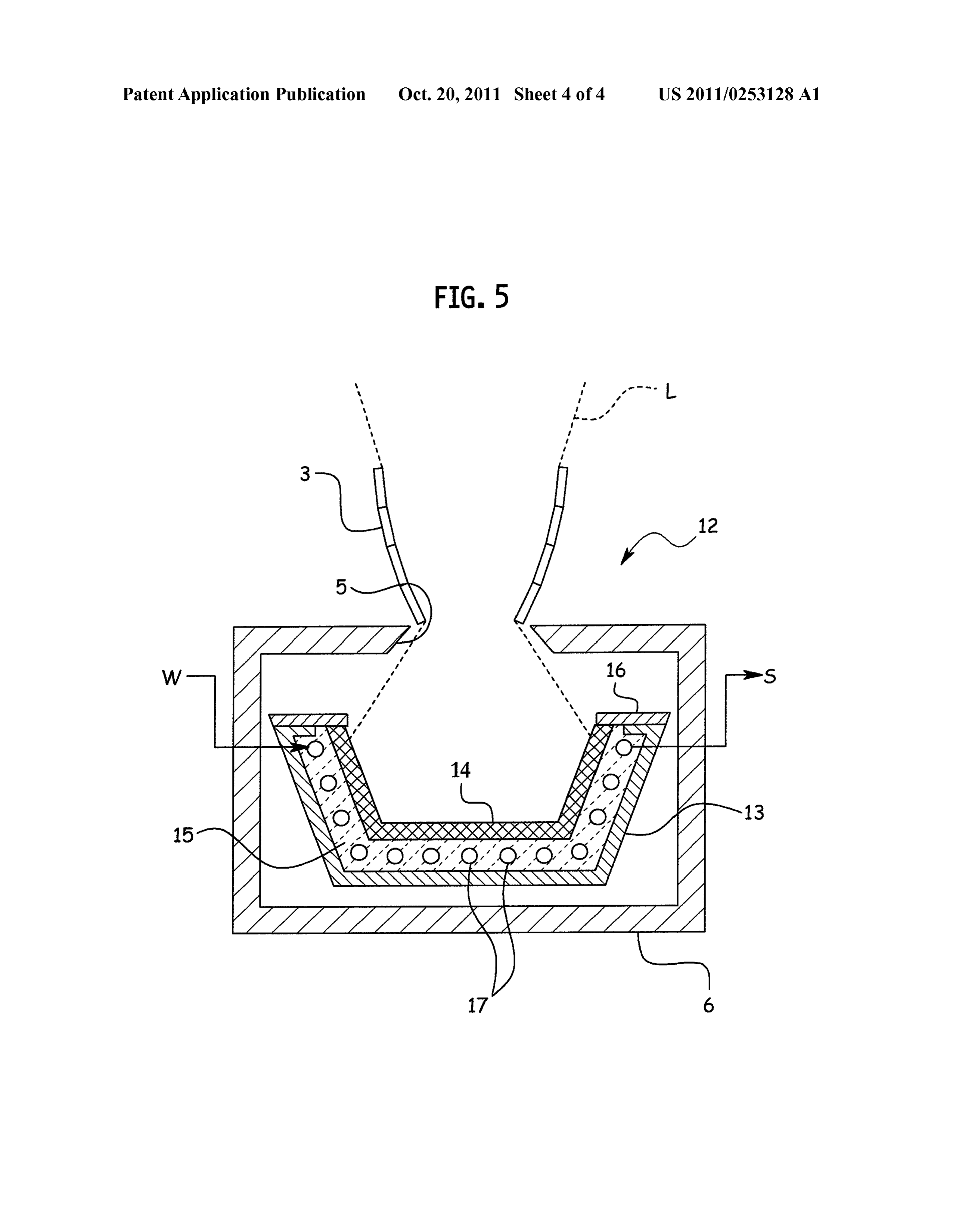
perature thereof reaches a melting point (232°C.). The mol 0007 FIG. 1 is a general view illustrating a solar concen tentin 8 in a wet state contacts the light receiving plate 9 and tration apparatus according to a first embodiment of the pipe 10, to increase heat conduction efficiency to Surely con present invention. vert the water W passing through the pipe 10 into vapor S. 0008 FIG. 2 is a sectional view illustrating a heat 0018. The black carbon material that forms the light exchanger. receiving plate 9 is smaller in specific gravity than the tin 8. 0009 FIG. 3 is a perspective view illustrating a light and therefore, the light receiving plate 9 floats on the surface receiving plate and heat-resistant container. of the tin 8 and never sinks into the tin 8 even if the tin 8 0010 FIG. 4 is an enlarged sectional view illustrating a becomes molten. The light receiving plate 9 is entirely coated silicon carbide film on the surface of the light receiving plate with the silicon carbide film 11. The silicon carbide film 11 and heat-resistant container. itself is highly heat resistive and prevents the inside black 0011 FIG. 5 is a sectional view illustrating a heat carbon material from contacting air, and therefore, the black exchanger according to a second embodiment of the present carbon material never burn even if the light receiving plate 9 invention. is heated to high temperatures.
0019. The heat-resistant container 7 is also coated with the
MODE OF IMPLEMENTING INVENTION silicon carbide film 11, and when an exposed part thereof First Embodiment receives solar beams L., the part absorbs the solar beams Land converts the same into heat to heat the tin 8.
0012 FIGS. 1 to 4 are views illustrating a first embodi 0020. In a first stage of the tin 8 receiving heat from the ment of the present invention. Numeral 1 represents an ellip light receiving plate 9, the tin 8 is solid and expands due to the tic mirror serving as a center mirror that is Supported with a heat. At this time, if the tin 8 and an inner face of the heat
Page 7
US 2011/0253 1 28 A1 Oct. 20, 2011
resistant container 7 are tightly attached to each other, stress be used alone, or may be mixed with Solid heat storage mate may concentrate on part of the tin 8 and heat-resistant con rial that does not melt when heated. tainer 7, to partly distort or break the container.
0021 For this, the embodiment forms the heat-resistant EFFECT OF INVENTION container 7 with black carbon material coated with the silicon 0028. According to the present invention, the light receiv carbide film 11. Compared with making the heat-resistant ing plate floating on the Surface of a low-melting-point heat container 7 from metal, contact force between the tin and the ing medium and receiving Solar beams is made of solid silicon container is weaker so that the tin 8 may easily slide on the carbide, or solid carbon material entirely coated with a silicon inner face of the heat-resistant container 7. In addition, the carbide film. Due to the silicon carbide film, the surface of the heat-resistant container 7 has an upwardly widening tapered light receiving plate is black to improve an absorption ratio of shape to allow the solid tin 8 to slide upwardly. As a result, the solar beams. The light receiving plate is formed with the tin 8 and heat-resistant container 7 will have no part where silicon carbide film at least at the surface thereof, and there stress concentration occurs to cause partial distortion or fore, demonstrates excellent heat resistance. The low-melt breakage. ing-point heating medium melts to become a liquid heat 0022. According to the present embodiment, the light Source that may take any shape depending on the shape of the receiving plate 9 and heat-resistant container 7 are made of heat-resistant container. This increases a contact area and black carbon material coated with the silicon carbide film 11. improves heat exchange efficiency. Instead, they may entirely be made of silicon carbide. 0029. The low-melting-point heating medium may be Although one piece of the light receiving plate 9 is floated on low-melting-point metal selected from any one of tin, lead, the surface of the tin 8, a plurality of small light receiving and solder, to serve as a high-temperature liquid heat source. plates 9 may be floated thereon. 0030 The low-melting-point heating medium may be 0023. According to the present embodiment, water W molten salt that is advantageous in terms of cost. passes through the pipe 10 and is converted into vapor S. 0031. The heat-resistant container has a tapered shape that Instead, the pipe 10 may pass air as the heat conducting fluid. upwardly widens. Even if the low-melting-point heating The airpassing through the pipe 10 is heated to high tempera medium causes in a solid state a Volume change due to ther tures and is circulated through another apparatus to conduct mal expansion during heating or cooling, the low-melting the heat from the tin 8 to the apparatus. point heating medium easily slides on the inner face of the 0024. Instead of the tin 8, low-melting-point metal such as heat-resistant container, to cause no stress concentration at lead and solder may be used as the low-melting-point heating any part of the low-melting-point heating medium and heat medium. resistant container. Accordingly, the low-melting-point heat ing medium and heat-resistant container never cause partial
Second Embodiment distortion or breakage.
0032. Further, the heat-resistant container is made of solid 0025 FIG.5 is a view illustrating a second embodiment of silicon carbide, or solid carbon material entirely coated with the present invention. This embodiment and embodiments a silicon carbide film, and therefore, even the heat-resistant that follow employ structural elements that are similar to container can absorb, at its exposed part, Solar beams and can those of the first embodiment. Accordingly, similar structural change them into heat. Compared with the case of making the elements are represented with common marks to omit over heat-resistant container from metal, contact force (a mutual lapping explanations. action at an interface) between the Solid low-melting-point 0026. A heat exchanger 12 according to the present heating medium and the container is weaker so that the low embodiment has a heat-resistant container 13 that is made of melting-point heating medium may easily slide when thermal stainless steel. A light receiving plate 14 is of an open-top type expansion occurs, thereby reducing stress on the heat-resis having a tapered side face that upwardly widens from a cir tant container.
cular bottom. Between the light receiving plate 14 and the 0033 Moreover, the light receiving plate has an open top heat-resistant container 13, there is molten salt 15 serving as container shape, to increase a light receiving area and an area a low-melting-point heating medium. The molten salt 15 is a in contact with the low-melting-point heating medium, so that mixture of potassium nitrate and Sodium nitrate and becomes the low-melting-point heating medium may quickly be put in liquid at a melting point of about 140°C. At an upper end of a molten state.
the heat-resistant container 13, a flange 16 is fixed to press from above the light receiving plate 14 that may rise due to UNITED STATES DESIGNATION buoyancy. In the molten salt 15, there is a pipe 17. 0034. In connection with United States designation, this 0027. According to the present embodiment, the light international patent application claims the benefit of priority receiving plate 14 has an open top shape to realize a large area under Article No. 119(a) of United States patent Law to to receive Solar beams L. In addition, a contact area thereof to Japanese Patent Application No. 2008-327647 filed on Dec. the molten salt 15 is also large. Accordingly, the molten salt 24, 2008 whose disclosed contents are cited herein. 15 can quickly be put in a molten state. Side faces of the light receiving plate 14 and heat-resistant container 13 are inclined 1. A Solar heat exchanger having a structure including a into a tapered shape and the molten salt 15 is heated even top-open, heat-resistant container holding a low-melting around the bottom of the heat-resistant container 13. Due to point heating medium and a light receiving plate being Sup this, the molten salt 15 in a molten state easily circulates due ported on and in contact with the Surface of the low-melting to convection, to relax temperature variations and further point heating medium, wherein improve heat exchanging efficiency. In addition, the molten the light receiving plate is made of solid silicon carbide, or salt 15 is inexpensive compared with, for example, tin, to Solid carbon material being entirely coated with a silicon provide an advantage in terms of cost. The molten salt 15 may carbide film.
Page 8
US 2011/0253 1 28 A1 Oct. 20, 2011
2. The Solar heat exchanger according to claim 1, wherein 5. The Solar heat exchanger according to claim 4, wherein the low-melting-point heating medium is low-melting-point the heat-resistant containeris made of solid silicon carbide, or metal selected from any one of tin, lead, and solder. Solid carbon material being entirely coated with a silicon 3. The Solar heat exchanger according to claim 1, wherein carbide film.
the low-melting-point heating medium is molten salt. 6. The Solar heat exchanger according to claim 1, wherein 4. The Solar heat exchanger according to claim 1, wherein the light receiving plate has an open top container shape. the heat-resistant container has an upwardly widening tapered shape. c c c c c
Provenance
- Collection
- Patents citing this work
- Original assignee
- Mitaka Kohki Co Ltd
- Pages
- 8
- Method
- pdftotext (the PDF's own text layer) + pdftoppm 300dpi page scans
- Patent office record
- patents.google.com →
- Source
- Google Patents citing-documents table
- Inventors
- Katsushige Nakamura; Mitaka Kohki Co Ltd
- Published
- 2011-10-20
- Transcribed from
- patentimages.storage.googleapis.com →