patent · US3938497
Apparatus for solar cooking
17 February 1976
Page 1 — bibliographic record
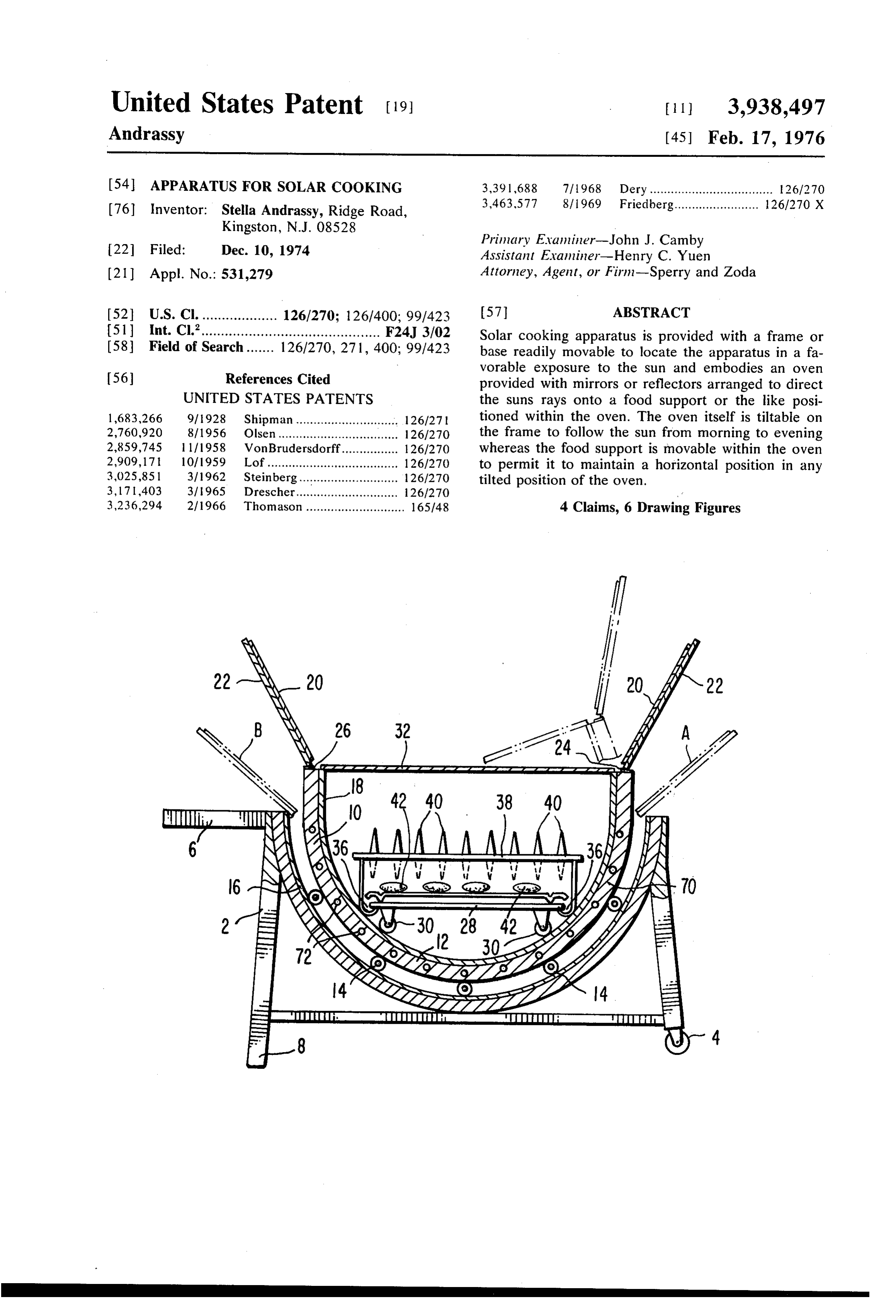
United States Patent (19) 11 3,938,497 Andrassy (45) Feb. 17, 1976 54 APPARATUS FOR SOLAR COOKING 3,391,688 7/1968 Dery................................... 26/270 (76) Inventor: Stella Andrassy, Ridge Road, 3,463,577 8/1969 Friedberg........................ 126/270 X Kingston, N.J. 08528
Primary Evanliner-John J. Camby 22 Filed: Dec. 10, 1974 Assistant Examiner-Henry C. Yuen (21) Appl. No.: 531,279 Attorney, Agent, or Firm-Sperry and Zoda
52 U.S. Cl. ................... 126/270: 126/400; 99/423 57 ABSTRACT 51 Int. Cl’............................................. F24J 3/02 Solar cooking apparatus is provided with a frame or 58 Field of Search....... 126/270, 271, 400; 99/423 base readily movable to locate the apparatus in a fa
vorable exposure to the sun and embodies an oven provided with mirrors or reflectors arranged to direct
UNITED STATES PATENTS the suns rays onto a food support or the like posi 1683,266 9/928 Shipman ............................. 126/27 | tioned within the oven. The oven itself is tiltable on 2,760,920 8/1956 Olsen ...................... ... 126/270 the frame to follow the sun from morning to evening 2,859,745 l l 11958 Von Brudersdorff................ 126/270 whereas the food support is movable within the oven 2,909,171 10/1959 Lof..................................... 126/270 to permit it to maintain a horizontal position in any 3,025,851 3/1962 Steinberg............................ 126/270 tilted position of the oven. 3, 171403 31 l965 Drescher............................. 126/270 3,236,294 2/1966 Thomason............................ 165148 4 Claims, 6 Drawing Figures
Page 2
Drawing sheet — no readable text.
Page 3
Drawing sheet — no readable text.
Page 4
The oven is formed to present a lower semi-cylindri
APPARATUS FOR SOLAR COOKING cal portion within which a food support or utensil is BACKGROUND OF THE INVENTION located. The food support is then provided with rollers or the like permitting the food support to be moved 1. Field of the Invention with respect to the oven so as to be maintained in a The advent of the present energy crisis has increased substantially horizontal position adjacent the center of the importance of alternative energy sources such as a the lower semi-cylindrical portion of the oven at all solar radiation. This invention deals with an improved times and when the oven is tilted to any angular posi apparatus for making use of solar heat for cooking. 10 tion to which it may be moved for effective exposure Solar ovens have been known in various forms since and reflection of the sun's rays into the oven. Further, the latter half of the nineteenth century. The purpose the oven is provided with upwardly and outwardly in of the present invention is to provide an apparatus for clined reflecting surfaces or mirrors for directing the cooking by using solar heat which cooks in approxi sun's rays toward the interior of the oven and onto the mately the same amount of time as normal cooking food support or tray located in the approximate center apparatus and also imparts the desired texture, temper 5 of the oven.
ature and color to the foodstuffs. A transparent cover or sheet of material formed of 2. Description of the Prior Art glass or plastic extends across the upper portion of the One of the most basic problems with solar ovens is oven and serves to confine the heat produced by ab the inability to follow the daily movement of the sun in 20 sorption of the suns radiation within the oven and its' semi-circular path from the east to the west. An about the articles on the food support. At the same other difficulty with following solar movement is that time the cover shields the food from wind and air cur throughout the day the angular altitide of the sun in the rents and protects it from access to flies, insects and sky changes continuously. The sun reaches an apparent dust to which it would otherwise be exposed. maximum height approximately at noon and is posi 25 In preferred forms of the invention special heat ab tioned intermediate between this maximum height and sorbing and transmitting covers are provided for the the horizon throughout the remainder of the day. food support or utensil to facilitate the heating or cook In association with this problem is the desire to main ing of particular foods or products within the solar tain the platform upon which the food is cooking at a OWel.
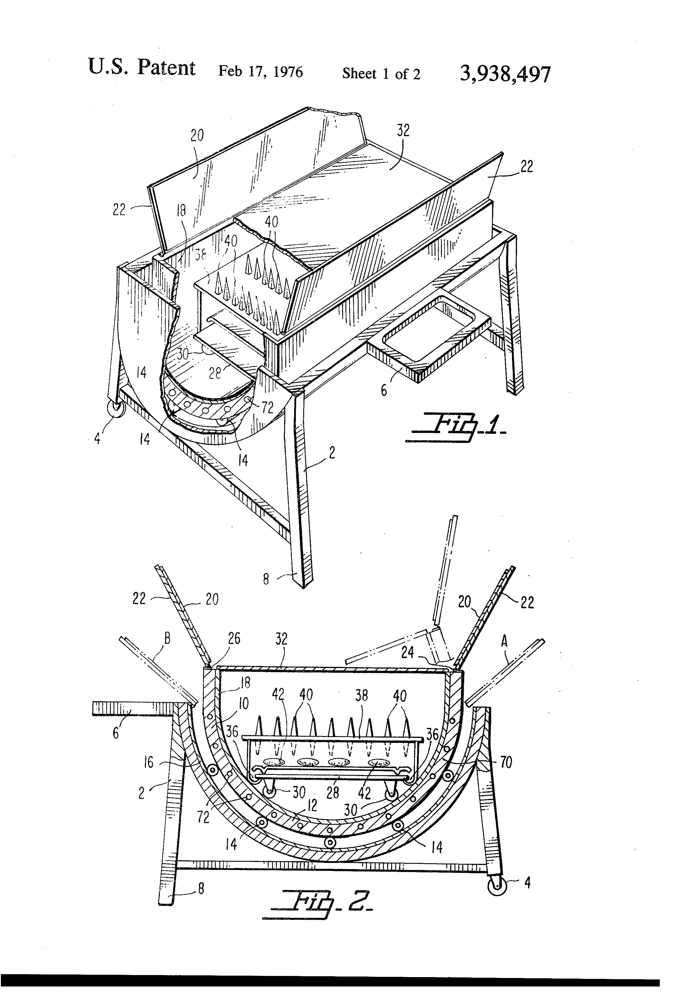
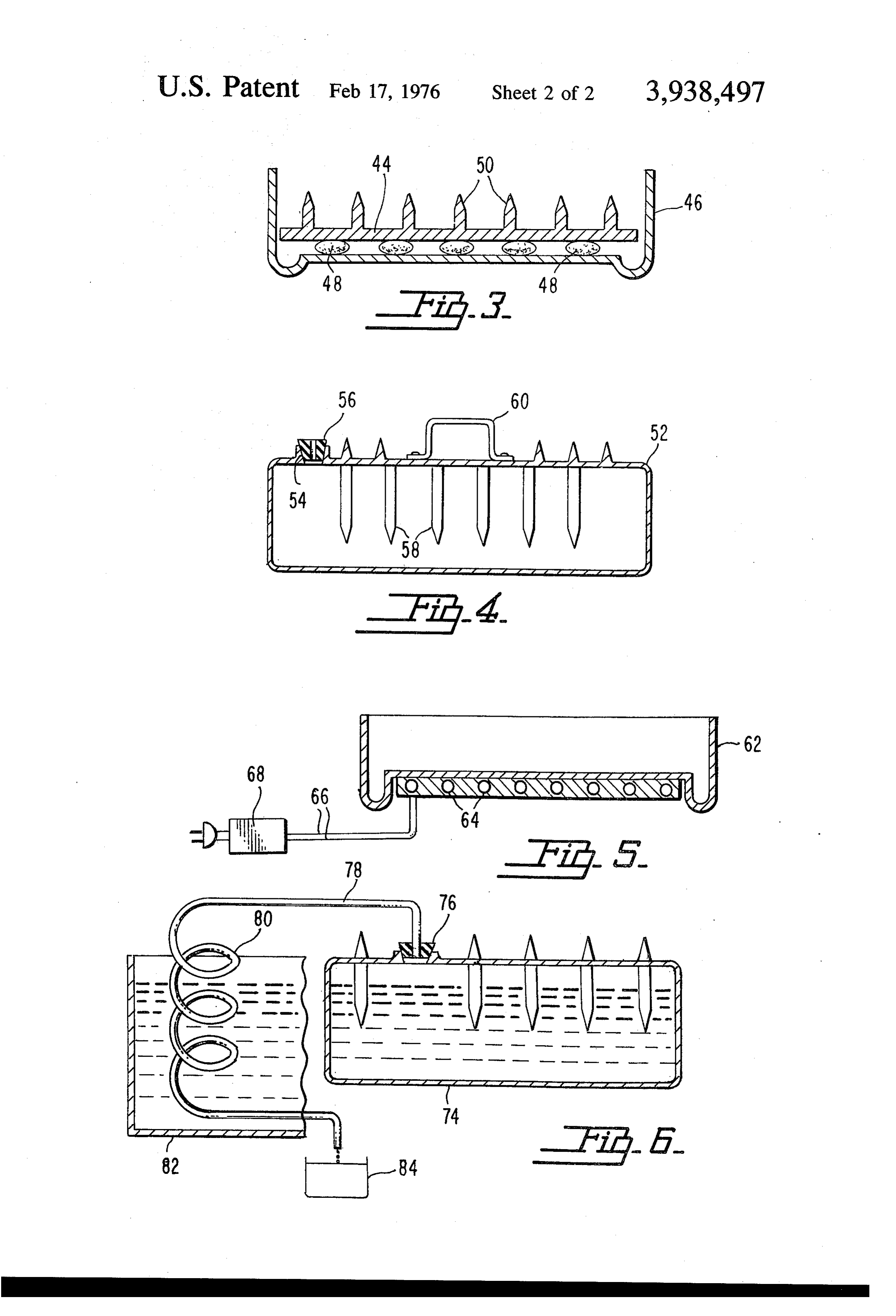
level attitude, irrespective of movement of the solar 30 BRIEF DESCRIPTION OF THE DRAWINGS oven shell itself. It is desirable to maintain this level attitude throughout the day with the most simple appa ment FIG. 1 is a perspective illustrating a typical embodi ratus possible. The simplicity is necessary since solar ken away; of the present invention with a part thereof bro ovens are inherently fine instruments and need to be FIG. 2 is a vertical sectional view of the apparatus relocatable to be sheltered during periods of bad 35 illustrated in FIG. 1; and weather and during the night. FIGS. 3 to 6 are vertical sectional views through Solar ovens have historically suffered from a depen special forms of utensils and covers therefor adapted dence upon weather conditions and a corresponding for use in the solar oven apparatus of the present inven lengthy cooking period. On overcast days where solar tion.
rays are shielded by cloud cover for long periods of 40 time the heat accumulated in the solar oven will be DESCRIPTION OF THE PREFERRED dissipated and the cooking activity will temporarily EMBODIMENTS cease. Often the sun will remain clouded over for suffi In that form of the invention chosen for purposes of ciently long periods to prevent the cooking function, illustration and even if the sun intermittently heats the oven, the 45 embodies ainframethe drawing, the solar cooking apparatus or support 2 which may be of any result is a sufficiently cooked foodstuff but without the suitable construction. As shown, the frame is provided normally desired texture and coloring. It is for these with wheels 4 and a handle 6 to enable the apparatus to reasons that solar ovens have been recognized up to the be readily moved about to position it in a desired loca present time as a mere curiosity. The disadvantages tion where it will be effectively exposed to the sun. A have overshadowed the many advantages of solar ovens 50 leg 8 is secured to the frame 2 and engagable with the such as the elimination of fire hazards, kitchen odors ground to hold the apparatus in a fixed position to and excessive household heat. These factors are all in which it has been moved.
addition to the fuel saving aspect of the solar oven. The The oven 10 is supported on the frame 2 and is present invention encompasses all these advantages formed with a lower portion 12 which is preferably and in addition overcomes the difficulties experienced 55 semi-cylindrical in shape and designed to rest upon in the prior art. rollers or other suitable bearing elements 14 mounted SUMMARY OF THE INVENTION upon arcuate or semi-circular member 16 of the frame 2. The oven 10 preferably presents a concave inner
The solar cooking apparatus of the present invention reflecting surface 18 adapted to direct reflected rays of embodies a frame or support which is readily movable 60 the sun inward toward the central portion of the oven. to position the apparatus in the most favorably exposed Additional reflecting surfaces 20 are provided on the location for receiving the sun's radiation. A solar oven inner surface of upwardly and outwardly extending is mounted on the frame and is supported on rollers or members 22 located adjacent the upper edges 24 and other bearing means which permit the oven to be tilted 26 of the semi-cylindrical lower portion 12 of the oven. to various positions so as to permit it to receive the 65 The members 22 and their reflecting surfaces 20 may maximum amount of sunlight as the sun moves from be adjustably movable if desired to most effectively east to west during the period when articles are to be concentrate the reflected rays of the sun on the articles heated or cooked. to be heated within the oven.
Page 5
The upper edges 24 and 26 of the oven project above same time, the cover 44 may be provided with pins or the adjacent sides of the frame 2 when the oven is in its heat transmitting elements 50 for increasing the area of central or vertical position as shown in full lines in FIG. the cover to which heat is transmitted to the articles 2 but is tiltable as shown in dotted lines A and B direct within the utensil 46.
the open upper portion of the oven toward the sun in The utensil 52 shown in FIG. 4 is designed for heating the morning and afternoon or at other times and to water as a tea kettle and for this purpose forms an position the additional reflecting surfaces 20 in the enclosure provided with an inlet opening 54 in which a most effective locations for directing the sun's rays intostopper or cap 56 having the usual whistle element is the oven. located. Heat transferring pins or fins 58 project in A tray or support 28 is located within the oven and 10 wardly from the top and bottom of the enclosure to provided with rollers or other bearing members 30 promote the transfer of heat to water in the utensil and engagable with the concave inner surface 18 of the a handle 60 is secured to the utensil to permit it to be oven. The article support 28 is thus movable with re tilted or handled in the same manner as a conventional spect to the oven 10 so as to continuously maintain a tea kettle.
horizontal position while the oven and its reflecting 15 In the construction shown in FIG. 5 the pan or utensil surfaces may be tilted or moved to positions which will 62 may be of any preferred shape but is provided in its serve to concentrate the sun's rays most effectively on base or elsewhere with an auxiliary heating element 64 any articles located on the support. including an electrical resistance device to which cur The oven is further provided with a transparent cover rent may be supplied through conductors 66 under 32 which extends across the oven above the article 20 control of a switch 68 that may be operated manually support and may be hinged or connected at one edge or by sensing means such as a thermostat, electric eye thereof to the edge 24 of the oven while the opposite or, the like. The construction thus provided renders it edge of the cover rests upon or is secured to the oppo possible to maintain the utensil 62 at a desired or con site edge 26 of the oven. The cover member 32 may be stant temperature at all times during a cooking opera formed of glass, transparent plastic or other material 25 tion and on cloudy or partially cloudy days when the which will effectively transmit the sun's rays and partic sun goes under a cloud. At the same time the maximum ularly the infrared rays which serve to develop heat utilization of solar heat and the maximum conservation upon contact with articles located on the support 28. of electrical energy is effected by the utilization thereof The cover 32 not only serves to confine the heat pro in combination as supplemental energy sources for duced within the oven but also serves to shield the 30 heating and cooking purposes. In this way a minimum interior of the oven from wind and air currents which consumption of electricity is assured while controlled might dissipate such heat and protects against the en and uniform cooking temperatures may be maintained. trance of dust, flies or insects which could otherwise In order to increase the efficiency of the apparatus come in contact with food being cooked out of doors. further the over 10 is preferably provided with heat The construction thus provided is movable about to 35 storage means such as thermal insulation extending permit it to be located in the most favorable position to about the sides of the semi-cylindrical lower portion 12 receive the direct rays of the sun while the oven itself is thereof as indicated at 70. In the alternative or in addi tiltable to focus the oven toward the sun and to change tion to such thermal insulation the oven may be pro its position from time to time as the sun moves from vided with heat storage means in the form of a chamber east to west during the period required to heat or cook 40 or tubes 72 containing a heat retaining liquid such as the articles on the support 28. At the same time the sodium sulfate, dehydrated castor oil or the like. In this article support is held in a level horizontal position way the temperature of the oven can be maintained at within the oven so that the articles being cooked or a constant and elevated temperature for long periods of heated will not be displaced on the support and any time and during cloudy periods when the sun is tempo drippings or other liquid from or about the articles on 45 rarily obscured.
the support will not be spilled. As illustrated in FIG. 6 the equipment of the present The article support 28 may serve as a cooking utensil invention may be used for distillation purposes to pu and as shown in FIG. 2 may be in the form of a pan rify water or for the development of low pressure steam within which a rack 34 is located whereas a marginal or for other purposes. Thus the chamber 74 may be trough or other depressions 36 may be provided in the 50 provided with a stopper 76 having a tube 78 passing bottom of the pan to receive liquids and drain them through the same extending to a coil 80 located on the away from the articles being cooked or heated. Further exterior of the apparatus where it may be positioned in if desired the support or utensil 28 may be provided the shade or in a tank 82 for delivering distillate to a with a cover 38 having heat transmitting elements 40 in receptacle 84 or the like. Such constructions are partic the form of pins or fins by which additional heat may be 55 ularly adapted for use in disaster areas, deserts or wher transmitted to or from the cover. Thus, as shown in ever contaminated water is prevalent. FIG. 2, the cover 38 may be formed with upwardly The constructions thus provided are highly efficient extending fins 40 for conducting heat most effectively and practical and not only serve to utilize solar energy from the space above the support to the cover 38. and to conserve fuels and energy which would other However, if desired the cover may be inverted to con 60 wise be used, but also are found to retain and enhance duct heat from the cover 38 directly to the food or the color, flavor and aroma of meats and other articles articles 42 enclosed between the support 28 and the which are heated or cooked therein. cover 38. While typical and preferred forms of equipment em Other types of utensils or article supports may be bodying the present invention have been illustrated in employed and as shown in FIG. 3 the cover 44 may be 65 the drawings and described above, it will be apparent of smaller area than the pan or utensil 46 so as to rest that numerous changes and modifications may be made directly upon articles 48, such as meat patties, to cook in the form, construction and arrangement of the ele them more rapidly and under limited pressure. At the ments of the combination employed. In view thereof it
Page 6
S 6 should be understood that the particular embodiments upper edges of said oven to direct solar radiations into thereof disclosed are intended to be illustrative only. the interior of said oven. I claim: 3. Solar cooking apparatus as defined in claim 1 1. A solar cooking oven comprising wherein:
a. a frame; a rollers are located between said oven and said b. an oven of concave configuration tiltably mounted frame to permit said oven to be moved to various on said frame to afford maximum exposure of the tilted positions for favorable exposure to the sun; interior of the oven to solar radiation; and c. an article support located in said oven adjacent the 10 b. additional rollers are located between said oven center thereof; and food support to permit said food support to be d. and rollers located between said oven and article maintained in a horizontal position when said oven support to permit movement of said support to a is moved from one tilted position to another. horizontal position in any tilted position of said 4. Solar cooking apparatus as defined in claim 1 OVC.
2. A solar cooking oven as defined in claim 1 wherein wherein eaS.
said oven is provided with auxiliary heating reflecting elements are movably mounted adjacent the sk ck ck ck ck
Provenance
- Collection
- Cited prior art
- Original PDF
- patentimages.storage.googleapis.com →
- Filed
- 1974-12-10
- Pages
- 6
- Method
- pdftotext (the PDF's own text layer) + pdftoppm 300dpi page scans
- Source
- Google Patents bibliographic record
- Granted
- 1976-02-17
- Inventors
- Stella Andrassy
- Transcribed from
- patentimages.storage.googleapis.com →