patent · US4184477
Solar heating and storage
22 January 1980
Page 1 — bibliographic record
United States Patent (19) 11 4,184,477 Yuan 45 Jan. 22, 1980 (54) SOLAR HEATING AND STORAGE Primary Examiner-James C. Yeung 76 Inventor: Shao W. Yuan, 6701 Montour Dr., Attorney, Agent, or Firm-William H. Holt Falls Church, Va. 22043 57 ABSTRACT 21 Appl. No.: 793,367 A system for utilizing and storing solar energy which 22 Filed: May 3, 1977 includes the use of solar collectors attached to liquid tubes or unidirectional heat pipes for transferring solar 51) int. C.’................................................. F24J 3/02 flux into heat energy for instant uses and storing the 52 U.S.C. .................................... 126/433; 126/435; heat energy into earth ground for auxiliary and long 126/436; 126/437; 165/105 term uses. An expanding array of heat conductive pipes 58) Field of Search ....................... 126/400, 270, 271; distributes the heat throughout a large volume of under 237/1 A, 59, 63; 165/105; 60/641; 62/333 ground earth and extracts the same when it is required. (56) References Cited The system provides for long-duration earth storage of the heat energy which can later be used as independent
3,262,493 7/1966 Hervey ................................. 126/27 homes, multiple-unit housing, commercial and public 3,774,677 1 1/1973 Antonetti et al. .................... 165/105 buildings, swimming pools, greenhouses, industrial 3,960,136 6/1976 Moan et al. .......................... 126/271 needs, etc.
4,000,851 l/1977 Heilemann ........................... 26/400 4,057,963 1 1/1977 Basiulis................................. 126/271 A unidirectional heat pipe, characterized by irreversible 4,061,131 12/1977 Bohanon .............................. 26/271 heat flow, including a pump arrangement for transfer 4,067,315 1/1978 Fehliner et al. ....................... 165/105 ring working fluid from the non-wicking condenser FOREIGN PATENT DOCUMENTS section to the evaporator section of the said heat pipe. 485296 1/1976 U.S.S.R. ................................... 165/105 9 Claims, 4 Drawing Figures
Page 2
Drawing sheet — no readable text.
Page 3
Drawing sheet — no readable text.
Page 4
Drawing sheet — no readable text.
Page 5
Drawing sheet — no readable text.
Page 6
Another important object of the invention is to pro
SOLAR HEATING AND STOERAGE vide for long-duration earth storage of solar energy which can be used at any desirable time for both space
BACKGROUND OF THE INVENTION heating and hot water heating systems in multiple-unit The invention relates to a system for collecting, dis cialhousing, public buildings such as schools etc., commer tributing, utilizing and storing solar energy, and more buildings or single dwellings, swimming pools, particularly, relates to a system which utilizes unidirec greenhouses, and industrial needs. tional heat pipes and the earth as means of transfer and provideA further and important object of the invention is to storage, respectively, of solar energy. an efficient means for transferring solar energy 10 from solar flux collectors into the thermal liquid tank
Prior art solar heating systems are generally accom plished by placing large collector plates on the roof and through the use of a novel unidirectional heat pipe in side structures of buildings. Liquids, such as water, are cluding an evaporator section, an adiabatic section, a condenser section and a working fluid, wick means piped through the collector, heated to a higher tempera disposed ture, and subsequently circulated through a building 15 transferring only in the evaporator section, and pump for and used as a space and tapwater heating medium. It a tion to the evaporatorthe working fluid from the condenser sec more elaborate application of the same principle, it has section. been suggested to place large tanks of water, rocks, malA liquid further object of the invention is to provide a ther tank and a heat storage reservoir in the earth stones, etc., in the ground and have heated water from the solar collector fed into the tanks where the heat 20 ground for instant and auxiliary supplies of energy for energy is stored and utilized for space and hot water the year-round space heating and hot water heating without heating. The above mentioned systems would lose their aid of conventional heating systems. effectiveness during prolonged cloudy or rainy weather anAefficient still further object of the invention is to provide for because of its incapacity to store more than a few days' ful heat andmeans of transferring solar energy into use a sufficiently large thermal earth storage supply of heat energy. This is particularly true of those 25 reservoir in order locations which have a large number of cloudy, rainy or solar collectors. to reduce considerably the amount of snowy days during the year, especially during the win A still further object is to provide an efficient means ter months when the heat is most needed, but when the to collect and store an abundance of solar energy during sunlight hours are shortest. Furthermore, a large solar the summer season for subsequent winter use when the collector area must be provided for constant supplies of 30 efficiency of collecting solar energy is extremely low energy for space and hot water heating during winter and the demand of energy is highest. months.
The present invention overcomes these disadvan Further objects and advantages of my invention will tages of the prior art by providing more efficient means become apparent from an understanding of the follow ing detailed description of preferred embodiments of for transferring solar energy for utilization and for long 35 my invention.
duration earth storage.
DESCRIPTION OF THE DRAWINGS
SUMMARY OF THE INVENTION
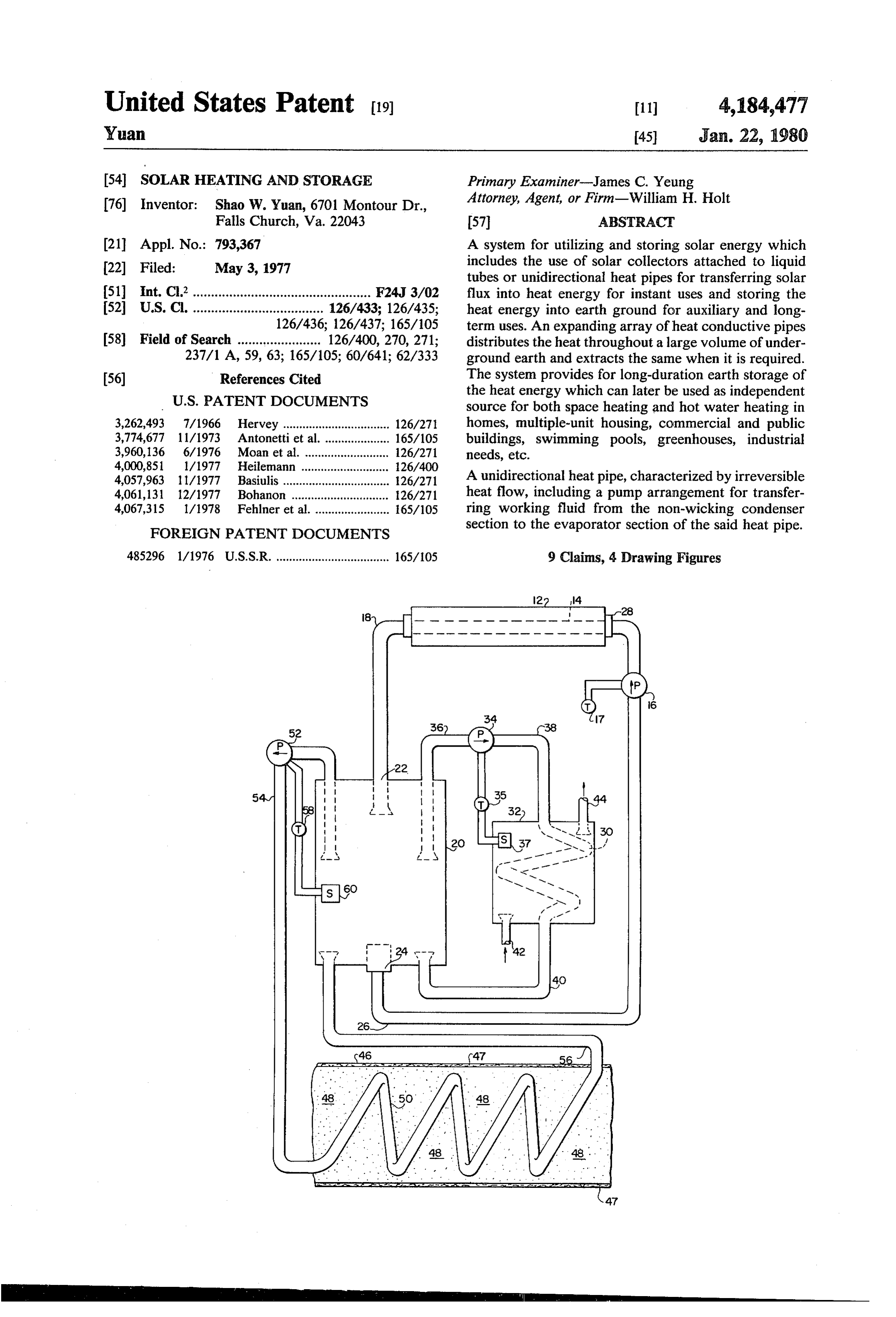
The present invention relates to a novel system for FIG. 1 is a diagrammatic sectional view of a system utilizing and storing solar energy wherein the system 40 for collecting, utilizing and storing solar energy in ac cordance with the present invention.
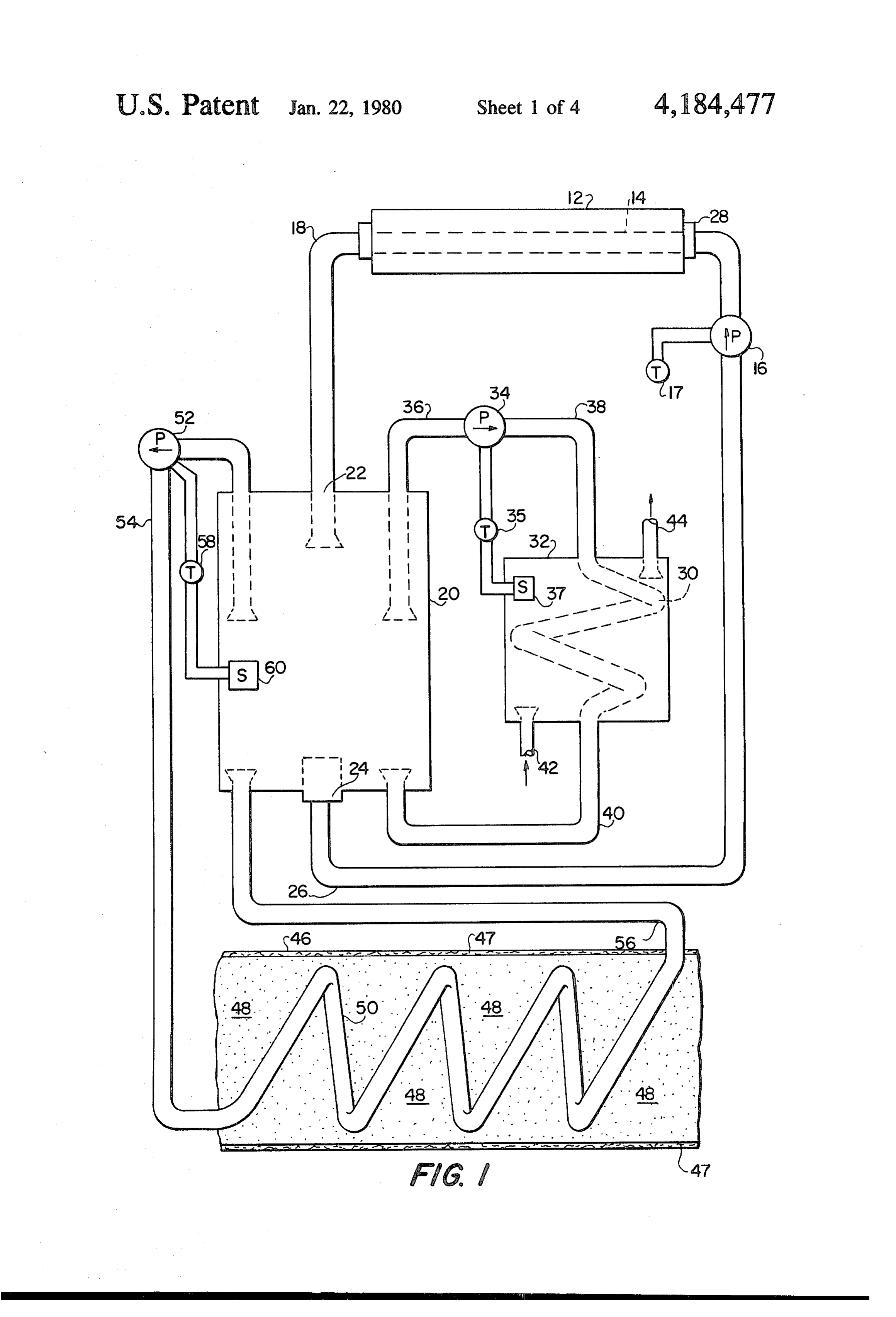
comprises a collector means for collecting solar energy FIG. 2 is a diagrammatic vertical section of a unidi and changing the solar energy to heat energy, means for rectional heat pipe constructed in accordance with the transmitting the heat energy from the collector means present invention.
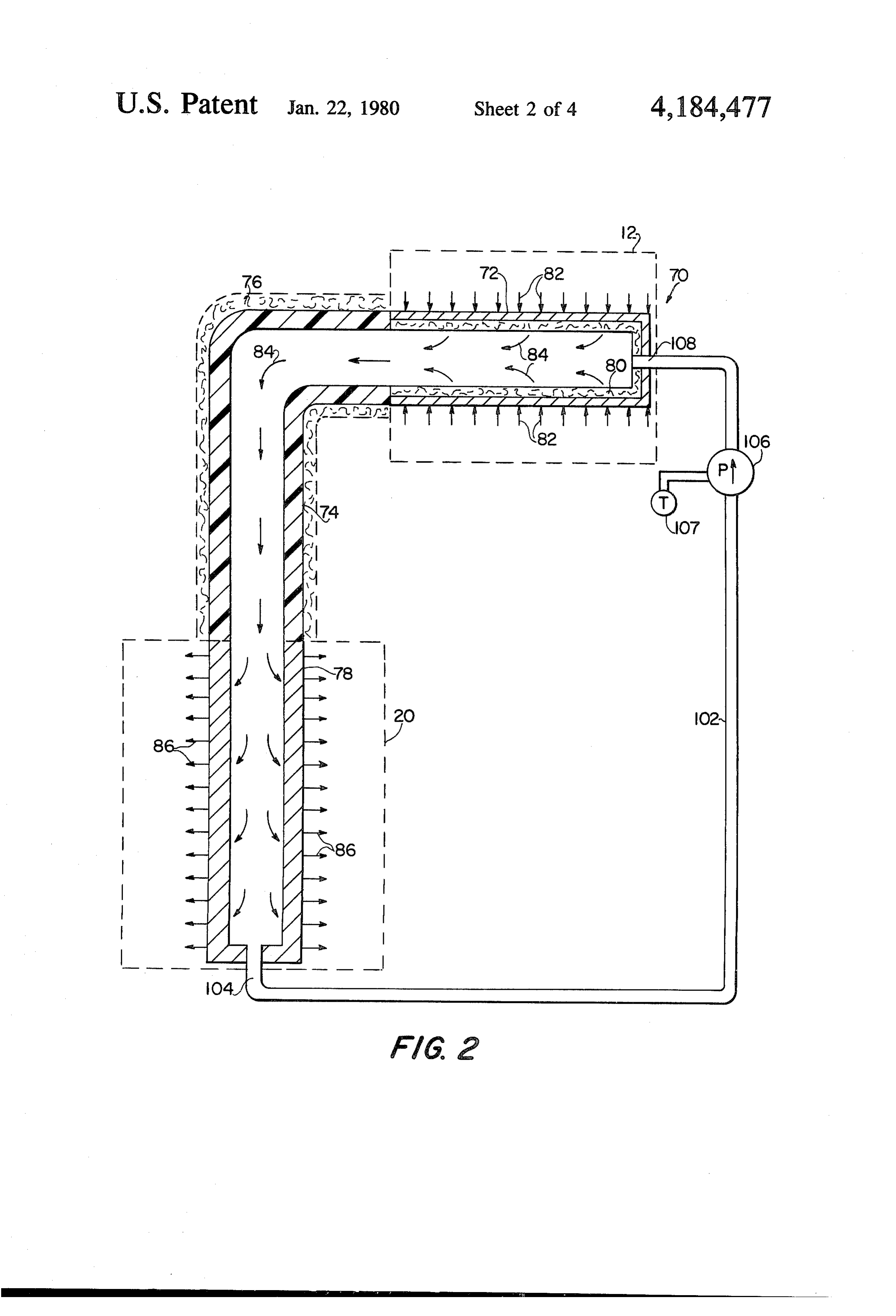
to liquid contained in a thermal liquid tank, and a dis FIG. 3 is a diagrammatic section view of a system for tributing means for distributing the heated liquid to a 45 collecting heat exchanger for space and hot water heating medium heat pipe insolar energy by employing a unidirectional accordance with the present invention.
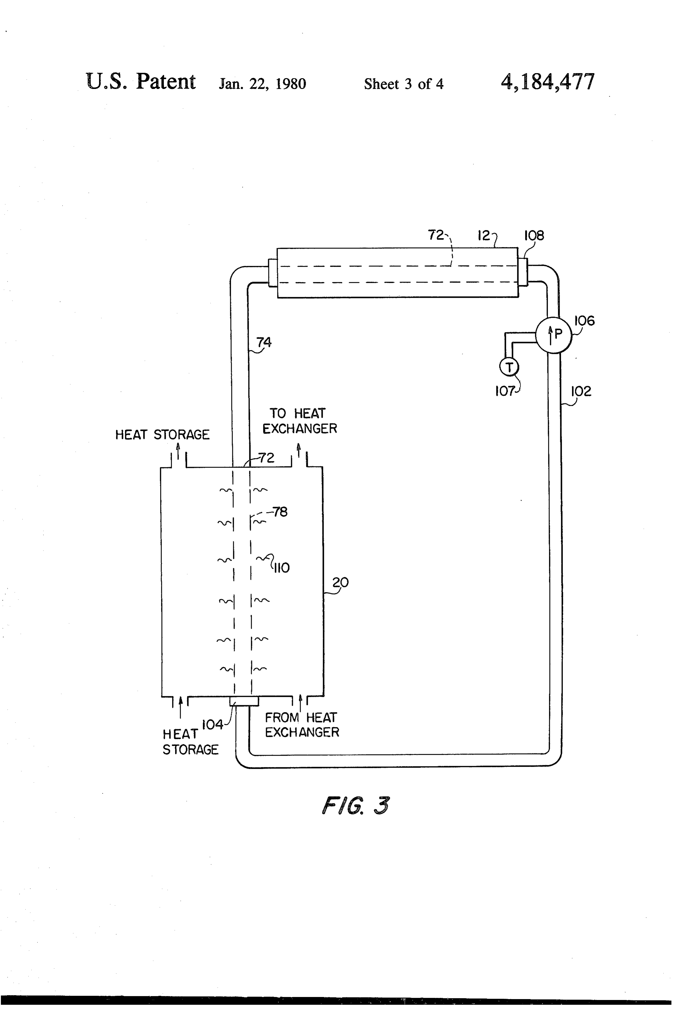
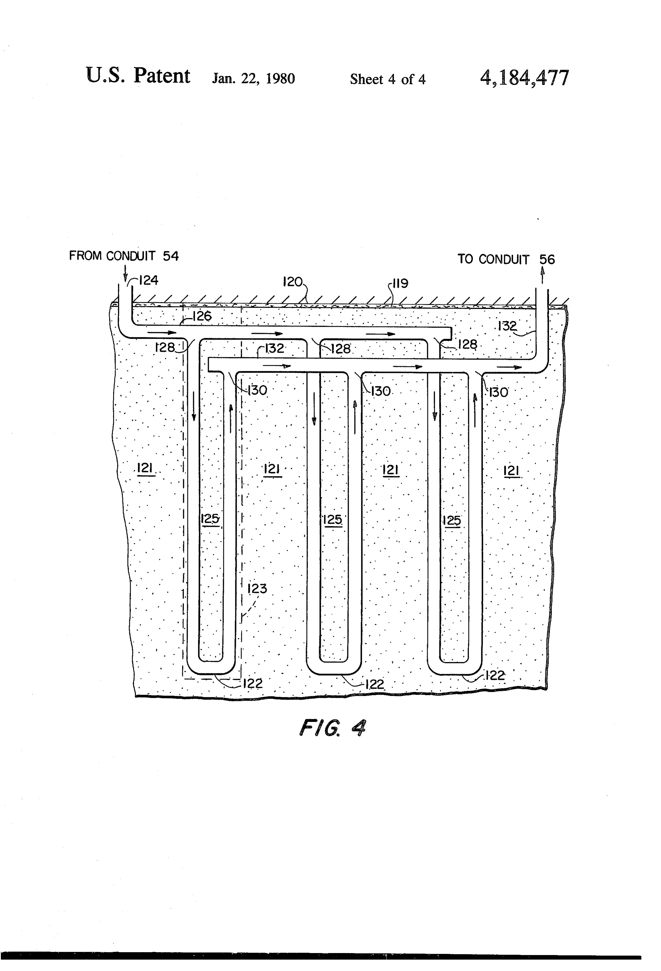
and to a ground reservoir for long duration storage. FIG. 4 is a diagrammatic section view of an alterna For accomplishing the foregoing objective, the in tive heat storage system in accordance with the present vention contemplates the use of solar collectors, liquid invention.
tubes or inidirectional heat pipes for transferring the 50 Referring to FIG. 1 the novel collection, utilization solar energy to the thermal liquid tank and the storage and storage system, generally indicated by number 10, ground, and piping loops for both transferring and stor including a conventional solar collector 12 which may ing of heat in the system, and extraction of heat from the be planar, tubular, parabolic, or any other type of col storage ground for space heat and hot water heating. lector, for collecting solar energy and transferring the The unidirectional heat pipe functions in the system as a 55 heat energy thereof to a heat absorbing tube 14 contain sort of rectifier, for transferring solar flux to useful heat ing a liquid heat transfer medium. The heated liquid energy, and allowing the heat energy to flow with the contained in the tube 14 is circulated by a pump 16 least possible resistance from the evaporator section of through conduit 18 and discharged to an insulated ther the heat pipe to its condenser section in the thermal mal tank or heater 20 through inlet 22 and returned to liquid tank during the period of time when the sun is 60 tube 14 through tank exit 24, conduit 26 and collector shining, but prevents the reverse flow of heat energy inlet 28. The process of collecting solar heat continues when the temperature near the solar collector is lower during the period of sunshine and operation of the pump than that of the thermal liquid tank. 16 is controlled by a thermostat 17 which turns off Accordingly, an important object of the invention is pump 16 when the sun is not shining.
to provide for a thermal liquid storage tank for heat 65 The heat utilization system includes the thermal tank energy which can be used for both space heating and 20 connected to a heat exchanger 30 inside a hot water hot water heating systems, and for long-duration earth heat utilization tank32. Heat energy is transmitted from storage. the thermal tank 20 to water tank 32 through heat ex
Page 7
changer 30. Pump 34 is located between conduit 36 and portion of earth 125 is replaced. I define “U-pipe' as a conduit 38 which connect the thermal tank 20 and hot fluid conveying pipe with entrance and exit ends water tank 32. formed like the upper part of a U shape. The remaining During normal operation pump 34 is automatically portion of said pipe may be of any desirable shape. The controlled or arrested by a thermostatic control 35 heat storage and the heat extraction methods of the responding to the water temperature measured by a system 820 are identical to that of the system 46 (see sensor 37 in the hot water tank 32. When the water FIG. 1). As one example of apparatus for using the hot temperature in the tank 32 drops below the preset range liquid in the thermal tank 20 (see FIG. 1) to store heat, of value, pump 34 starts automatically and hot water in the hot liquid from conduit 54 enters the storage system the heater 20 will be circulated through the heat utiliza 10 120 at inlet 124 of the receiving pipe 126. The liquid tion system by passing through conduits 36 and 38 into flows into the U-pipes 122 at inlet 128 and leaves at exit the heat exchanger 30 in the hot water tank 32, and 130 to the delivering pipe 132. The liquid then flows returning to the thermal tank 20 through conduit 40. through pipe 132 back to the thermal tank 20 (see FIG. The process of circulating hot water through the heat 1) through conduit 56 (see FIG. 1). The process of utilization system continues until the preset water tem 15 circulating hot liquid through the heat storage system perature in the said water tank 32 is reached, and the 120 continues until a preset liquid temperature in the pump 34 will be shut off automatically by thermostatic thermal tank 20 (see FIG. 1) is reached, and the pump control 35. 52 (see FIG. 1) will be shut off automatically by thermo As is obvious, when cold water flows into the water static control 58 (see FIG. 1). A similar manner of circu tank 32 through the inlet 42 it will absorb heat from the 20 lating the liquid through the heat storage system 120 heat exchanger 30. The heated water in the water tank can be applied for the case of heat extraction. 32 may be directed through the outlet 44 to any suitable While the foregoing description of the invention has place for storage or use. For example, the heated water been limited to only a single series of U-pipes 122, it will could be circulated through the heating system of a be readily understood that multiple series of U-pipes residence but certainly could be used for any other 25 may be added to the heat storage system. heating purpose and hot water needs. In order to increase the efficiency of the heat storage The heat storage system 46 consists of a volume of system, a layer of insulating material 119 is disposed sand or packed bed 48 and an expanding array of pipe about on the surface of the earth, and preferably, the 50. When the water temperature in the thermal tank 20 insulating material 119 is black plastic sheets, or the like, is raised to a desired temperature (during sunshine), the 30 to serve as a vapor barrier and also to aid in collecting thermostatically controlled pump 52 will start to circu additional heat from the solar flux and transmitting such late the hot water (counterclockwise) through conduit heat into said heat storage system. It is to be understood 54 to the heat storage unit 46 through the expanding that similar insulating material may be placed along array of pipe 50 and passing through the conduit 56 sides of said heat storage system, if required. back to the thermal tank 20. The process of circulating 35 FIG. 2 illustrates the constructional details of a pre hot water through the heat storage system continues ferred unidirectional heat pipe, generally indicted by until a preset water temperature in the thermal tank 20 the numeral 70, which is utilized as an alternative col is reached, and the pump 52 will be shut off automati lection system of solar energy. The unidirectional heat cally by a thermostatic control 58 and sensor 60. pipe 70 includes an evaporator section 72, an adiabatic When it is desired to use some of the heat that has section 74 covered with a layer of insulating material been stored in storage unit 46 (i.e., the water tempera 76, and a condenser section 78 as well as containing a ture in the thermal tank 20 drops below the preset range working fluid (not illustrated). The evaporator section of value) the pump 52 will be started by thermostatic 72 is lined with a wick 80 and the adiabatic section 74 control 58, and the water is circulated from the thermal and the condenser section 78 are not lined with a wick. tank 20 through the array of pipe 50 in the heat storage 45 The wick 80 may be metal, such as wire screen, sintered unit and back to the tank 20 in a counterclockwise metal powder or fiber, or perforated sheets, or it may be sense. It is, of course, to be understood that the water in a non-metallic material such as felt, cloth, or fiberglass. the array of pipe 50 picks up the heat energy of the The working fluid may be water, ammonia, acetone, surrounding sand 48 as it passes through the heat stor fluorocarbons (refrigerants), alcohols, and various liq age unit 46. Again, the pump 52 is shut off by thermo 50 uid metals. However, only enough working fluid to static control 58 when the hot water in the tank 20 saturate the wick is introduced into the unidirectional reaches a preset temperature. heat pipe 70. The choice of container, wick material, While the foregoing description of the invention has and working fluid combination is based on the opera been limited to only a single array of pipe 50, it will be tions and design criteria of the heat pipe application. readily understood that multiple arrays of pipe 50 and 55 In evaporator section 72 heatenergy, indicated by the additional heat absorbing tubes 14 may be added to the arrows 82, is received from the solar collector 12 and is said solar heating system 10. transferred by conduction through the outer wall of the In order to increase efficiency of the heat storage evaporator section 72. The heat energy 82 causes the system, a layer of insulating material 47 is disposed working fluid to vaporize, as indicated by the arrows along both top and bottom surfaces of the heat storage 84. The vaporized working fluid then flows down system. It is to be understood that similar insulating wardly through the adiabatic section 74 to the con material may be placed along sides of the heat storage denser section 78 where the vapor condenses and the system, if required. heat energy is transmitted outwardly through the wall An alternative heat storage system 120 is shown in of the condenser section 78, all as is indicated by the FIG. 4. The system consists of a volume of unprepared 65 arrows 86. It is to be understood this heat, as indicated earth 121 with a series of drilled wells (one being indi by the arrows 86, is the heat given up in the thermal cated by broken lines 123) of predetermined depth. A tank 20 of FIG. 3. In order to increase the heat transfer series of long U-pipes 122 are buried in the wells and a rate from the solar collector to the thermal tank liquid,
Page 8
metal fins 110 (see FIG. 3) may be mounted along the heat storage means, a heat utilization tank, and means condensation section 78 of the unidirectional heat pipe for recirculating heat energy between said thermal tank 70 for more effectively removing heat therefrom. and said heat utilization tank, said solar collector means In order that unidirectional heat pipe 70 operates in a including a unidirectional heat pipe including an upper continuous manner, it is necessary that the working evaporator section, an adiabatic section and a lower fluid condensate in the condenser section 78 be returned condenser section, said evaporator section being ex to the evaporator section 72. This return of working posed to solar heat energy and said condenser section fluid is provided by the provision of a return line 102 being immersed in said thermal tank, said unidirectional which is connected to a port 104, at the bottom of the heat pipe further including wick means disposed in said condenser section 78, and connected to a pump 106 O evaporator section and a working fluid contained which is, in turn, connected to a port 108 at the evapo within said heat pipe, characterized by an absence of rator section 72. It is to be understood that the pump any wick means in said adiabatic and condenser sec 106 is preferrably operated only one-way in the direc tions, conduit means extending externally of said heat tion to return working fluid from the condenser section pipe and connecting said condenser section to said 78 to the evaporator section 72. This is an important 15 evaporator section, and pump means in said conduit part of the energy collecting system (see FIG. 3) so that, means for pumping condensed fluid from said con when the collector 12 is not effectively operating and denser section and into said evaporator section. the ambient temperature around the evaporator section 2. A system as defined in claim 1 wherein said heat 72 is lower than the hot liquid temperature in the ther storage means comprises a considerable volume of soil mal tank 20 around the condenser section 78, the unidi like material, and heat distributing means for distribut rectional heat pipe 70 is irreversible; in other words, ing said heat energy throughout said volume of soil-like heat energy is not transmitted upwardly through the material positioned below ground level. adiabatic section 74 and lost to the atmosphere through 3. A system as defined in claim 2 wherein said heat the evaporator section 72. distributing means comprises an array of pipes formed When the solar energy is not available, or during 25 of heat conductive material, said array of pipes extend extremely cold weather, the pump 106 will be shut off ing throughout said heat storage means, and means for automatically by a thermostatic control 107. This pre causing a heat transfer fluid to flow within said pipes. vents the reverse vapor flow in order to avoid heat 4. A system as defined in claim 1 wherein said heat losses from the thermal tank 20 to the surrounding envi storage means includes heat extraction means for ex ronment. As an additional measure to prevent heat loss 30 tracting heat from said heat storage means and deliver by axial conduction of heat upwardly through the unidi ing heat to a desired location.
rectional heat pipe 70, the adiabatic section 74 is made 5. A system as defined in claim 1 wherein said heat of a poor heat conductive material. Thus, the condenser storage means includes heat insulating means located section 78 is insulated from the evaporator section 72. along at least one side of the heat storage means for The foregoing description teaches that a unidirec 35 minimizing heat losses to adjacent surfaces. tional heat pipe can be employed to transfer solar en 6. A system as defined in claim a wherein said heat ergy from the collector 12 to the thermal liquid tank as storage means comprises at least a volume of soil-like depicted in FIG. 3. The heat utilization system and the material positioned below ground level, and a plurality heat storage system can be identical to those shown in of horizontally spaced substantially vertically extending FIG. 1, or the heat storage system shown in FIG. 4. 40 distributing means, that can be positioned in holes While preferred storage and utilization systems and a drilled in said soil-like material for distributing said heat preferred unidirectional heat pipe for use in such sys energy to said heat storage means. tems have been illustrated and described, it is to be 7. A system as defined in claim 6 wherein said heat understood that various changes and arrangement of distributing means comprises a long U-pipe of heat parts may be made without departing from the spirit 45 conductive material buried in said soil-like material, and and scope of the invention as defined in the appended means for causing a heat transfer fluid to flow within claim subject matter. said pipe.
I claim: 8. A system as defined in claim 6 including heat ex 1. A system for collecting, storing and utilizing solar traction means for extracting heat from said heat stor energy, said system including a thermal tank containing 50 age means and delivering said heat to a desired location. a liquid and being substantially filled thereby, solar 9. A system as defined in claim 6 including heat insu collector means for transmitting heat energy to said lating means located along at least one side of the heat thermal tank, heat storage means, means for transmit storage for minimizing heat losses to adjacent surfaces. ting heat energy to and from said thermal tank and said : s : k
Provenance
- Collection
- Cited prior art
- Original PDF
- patentimages.storage.googleapis.com →
- Filed
- 1977-05-03
- Pages
- 8
- Method
- pdftotext (the PDF's own text layer) + pdftoppm 300dpi page scans
- Source
- Google Patents bibliographic record
- Granted
- 1980-01-22
- Inventors
- Shao W. Yuan
- Transcribed from
- patentimages.storage.googleapis.com →