patent · US2145468
Circuit breaker
31 January 1939
Page 1
Drawing sheet — no readable text.
Page 2
Patented Jan. 31, 1939 2,145,468
UNITED STATES PATENT OFFICE
CIRCUIT BREAKER,
Paul Wangemann, Berlin, Germany
Application May 1, 1936, Serial No. 77,445
In Germany December 23, 1935
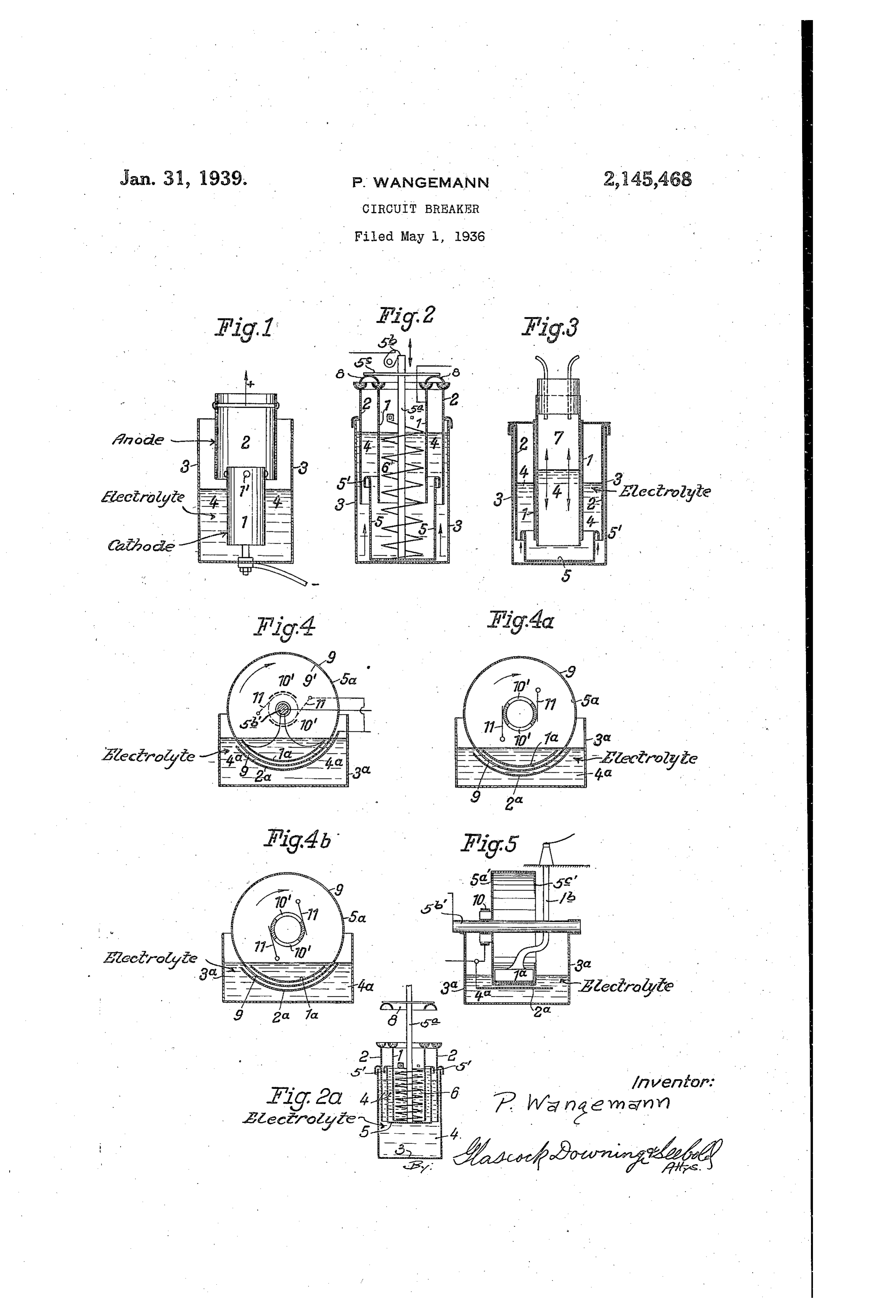
This application is a continuation-in-part of the circuit is broken by the interposition of an applicant's application S. N. 2,131 filed January, insulating shield between the electrodes. 16, 1935. Fig. 2d shows the device of Fig. 2 in open cir This invention relates to circuit breakers and cuit position.
5 has for an object to provide improved construc Fig. 3 shows in vertical section a further modi tions for the sparkless making and breaking of fication suitable for use with either direct or circuits carrying very high currents. alternating current, in which the circuit is broken A further object is to provide improved means by the partial removal of the electrolyte from for this purpose in which electrodes are im between the electrodes and the interposition of 10 10 mersed in a conductor of the second class, such an insulating shield.
as an electrolyte. Fig. 4 shows a vertical sectional view of a modi It has been discovered that sparkless inter fication utilizing a rotating insulating cylinder. ruption of currents can best be effected when the Fig. 4a and Fig. 4b are views corresponding to cathode remains immersed in the highly con Fig. 4 but showing in different positions of ad 15 5 ductive electrolyte at the moment when inter justment the brushes forming a part of the de ruption occurs, and it is thus another object of Vice shown in Fig. 4.
the invention to provide an improved electro Fig. 5 is a vertical Sectional view of a slightly lytic circuit breaker in which the cathode re modified device of Fig. 4 taken at right angles mains immersed in the electrolyte at the moment to Referring the Section of Fig. 4.
to Fig. 1 of said drawing, the nu 20 20 of interruption.
Since in alternating current circuits it is not meral 3 represents a suitable vessel, preferably possible to foretell which of the two electrodes made of insulating material, and which contains will be the cathode at the instant of interruption, thea Suitable conductor of the second class such as Special constructions are necessary. It is, there highly conductive electrolyte & which may be 25 fore, a further object of the present invention to a strong solution of KOH as described in British 25 provide Such an improved circuit breaker in patents to Martin Paul and Paul Wangemann Which means are provided to assure that the (the present applicant) Nos. 331,852 and 333,022. electrode which at the instant of interruption is Within said electrolyte is shown the fixed elec the cathode, is immersed in the liquid at the Wated trode . The movable electrode 2 is shown ele 30 instant of interruption. out of the electrolyte. To close the circuit 30 Another object is to provide circuit making the electrode 2 may by suitable means, be moved . means in which a circuit is first established down into the electrolyte, at which time the cir through an electrolyte or other second class con cuit Will be closed through the conductor shown ductor and then a parallel circuit is established connected to the electrode , the second class 35 35 through a metallic connection, i. e., a conductor conductor A, the electrode 2, and through a suit of the first class, and in which the circuit is in able conductor (not shown) connected to the terrupted first by breaking said shunt metallic electrode 2. In order to prevent possible metallic circuit and then by breaking the circuit through ing contact between the electrodes, Suitable insulat the second class conductor. means may be provided Such as the insulat A further object is the provision of a process ing knobs on electrode . 40 of making and breaking circuits as herein de In order that the form shown in Fig. 1 Will Scribed and claimed. operate in accordance with the present invention Further objects and advantages of this inven itcathode was found that the electrode must be the to aSSure dependable sparkless interrup tion. Will be apparent from consideration of the tion of heavy currents. An explanation of this 45 5 specification as illustrated by the accompanying phenomenon is not necessary here, but it may be drawing of possible embodiments of the inven Stated that since the cathode remains immersed tion, in which drawing: no cathode spot is formed and that therefore, Fig. 1 shows, in Vertical Section, one possible the formation of an arc is prevented. form of circuit breaker suitable for practicing the Figs. 2 and 2a illustrate a circuit breaker 50 invention, Suitable for use in a direct current adapted for alternating current. As it is impos circuit. sible to determine which electrode will be the Fig.2 shows, in vertical Section, a modified form cathode at the instant of interruption, it was of the invention for use in either a direct cur found necessary to SO construct the circuit breaker for alternating current that neither 55 rent or an alternating current circuit, in which
Page 3
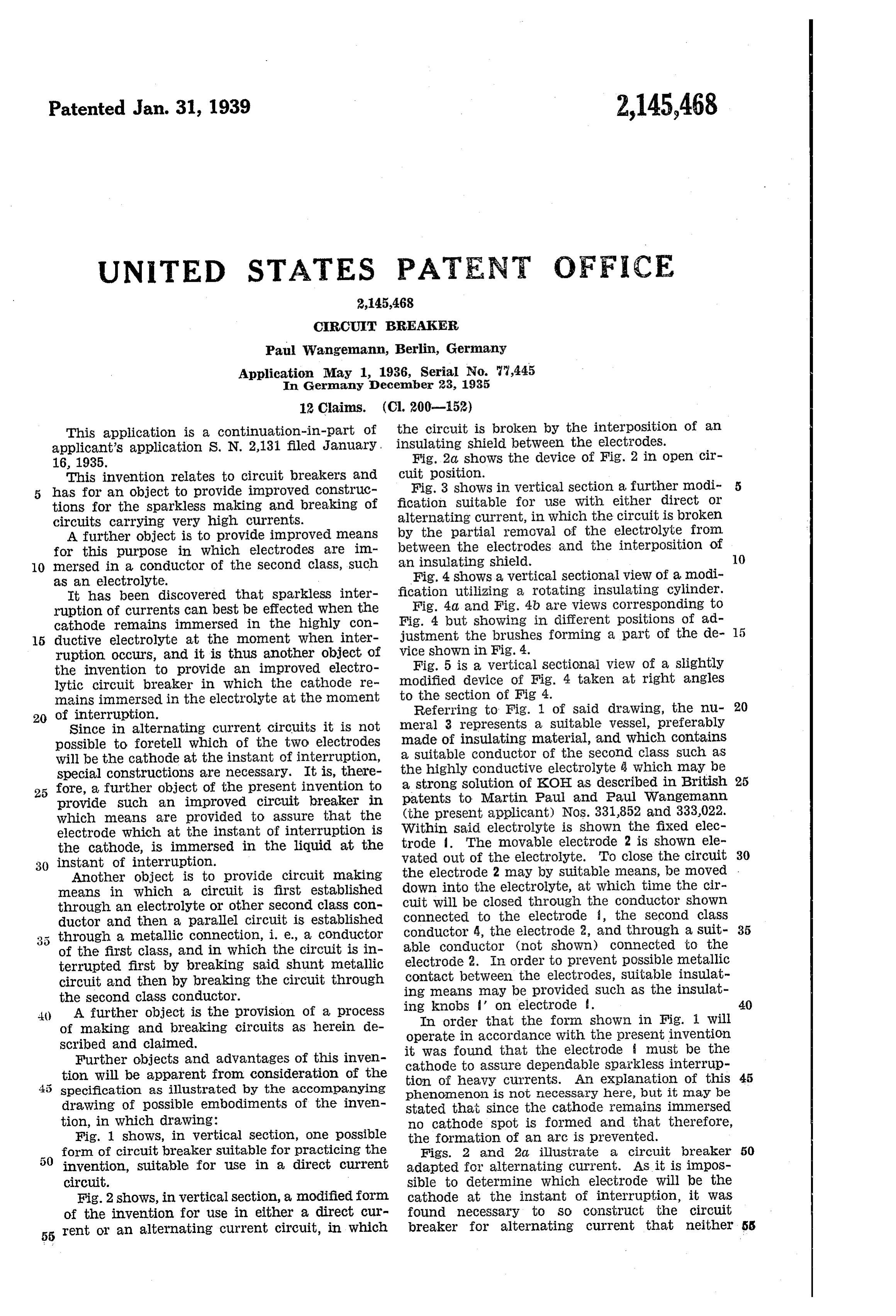
electrode is withdrawn from the electrolyte. In part of the electrolyte will flow up into the cham this construction, the container 3 is substantially ber 7 and therefore flow away from the space be filled with the electrolyte 4. Continuously im tween the electrodes until the circuit is broken mersed within the electrolyte are the two elec at the instant When the top surface of the electro trodes and 2, shown in the form of cylinders. lyte becomes lower than the top edge of the in Neither one of these electrodes is moving during Sulating cup 5 which, again, is preferably pro the circuit making or breaking operation. Also vided with an air trap 5'. In the form shown, located within the electrolyte is a cup or the it will be seen that the circuit breaking action like 5, made of insulating material. The cup is Will be expedited by the floating of the cup 5 as 0 mounted for vertical movement So that when it Soon as the iiquid level therein drops below its is lifted from the position shown in Fig. 2 to the top edge. It Will be noted that the lower ends O position shown in Fig. 2d., it Will progressively of the electrodes and 2 remain covered to a interrupt the circuit between the electrodes and Substantial extent by the electrolyte and that 2 and when the upper edge of cup 2 emerges from therefore extremely high current densities upon 5 the electrolyte, the circuit will be entirely broken, the electrode Surfaces are avoided. the break occurring While a Substantial Surface Figs. 4, 4d, 4b, and 5 illustrate a circuit breaker of each electrode is Submerged, so that extremely Of the rotary type operating in accordance With high current density on the electrode surface is the present invention. Such a device may be used avoided. not only in the usual manner as a circuit breaker For the purpose of securing the desired ver for producing single interruptions, but also for 20 tical movement of cup 5, it may be carried by a use as controllers, mechanical rectifiers, etc. In rod Sa and normally tensioned spring 6 may be these figures, as in the construction shown in provided to move the insulating cup 5 upwardly FigS. 2 and 2d, the electrodes a and 2a are con when the holding pawl 5b is released. The upper tinuously innersed in the electrolyte and the edge of the cup 5 is preferably provided with an electrolytic path between them is interrupted air trap to prevent creeping current immediately as required on Occasion by passing an insulating after the circuit is broken. This may be easily Shield therebetween. The electrolyte 4a is con accomplished by having the top edge of the cup tained in a receptacle 3d and the electrode 2a, turned back upon itself, as shown at 5'. Air Will at least one side of which is curved, is firmly 30 be trapped within the annular Space, as a result Supported within said receptacle by any suitable 30 of which the surface Within the trap will remain insulated means. The electrode a, the outer dry, thus precluding the possibility of Creeping face of which is correspondingly curved, is also Currents. firmly Supported within the electrolyte by suit It has been found desirable also to provide a able insulated means Such as by suspending it 35 shunt or bridging contact, preferably of a metal from the shaft 5b as shown in Fig. 4 or support 35 lic nature. This may be accomplished by pro ing it upon an insulated support as the bracket viding an arm or disk 5c upon the rod 5d and b (Fig. 5). The insulating shield may consist forming upon said arm or disk a Suitable bridg of a drum 5d having one cylindrical wall 5a' at ing conductor 8 which makes metallic contact tached to and carried by the shaft 5b' appropri with electrodes and 2. ately journaled relative to the electrodes. The 40 With this construction it will be noted that cylindrical Wall of said drum is provided with When the cup is moved upWardly, the Shunt cir one or more openings 9 to provide a conducting cuit, through the metallic switch, will first be path, as required from time to time, between the broken, whereupon all of the current is caused to electrodes a, 2a, through the electrolyte 4d. At flow through the electrolyte 4, between the elec tached to the outer free end of the cylindrical trodes and 2. Upon further rising of the cup 5, Wall is an in Wardly extending flange portion 5c' 45 the electrolytic path is gradually cut off until to complete the interruption of the path through the top edge of the cup 5 emerges fron the elec the electrolyte. The slots 9 may, if desired, be trolyte. As soon as the skirt member 5’ has closed by means of a metal plate to prevent un emerged from the electrolyte, the dry Surface due agitation of the electrolyte which might Within the air trap will prevent also the flow of otherwise occur at high rotational speeds. Creeping currentS. In order to provide a shunt metallic switch, It will be seen, therefore, that this form of the it may be desirable to provide a commutator, invention provides electrodes innersed in an Such as the metallic segments O', which rotate 55 electrolyte together with means for breaking the as a unit With the insulating drum shield 5a, and circuit between said electrodes through Said elec are engaged by brushes , preferably mounted 55 trolyte without withdrawing either electrode for rotative adjustment relative to the com from the electrolyte, whereby it is assured that mutator Segnents.
the electrode which, at the instant of interrup By adjusting the brushes to the position shown (60 tion is the cathode, is certain to be immersed in in Fig. 4b and connecting them in the circuit con the electrolyte at the instant of interruption; and trolled by the circuit breaker as shown in Fig. 4, 60 in which an electrode bridging metallic switch a short circuiting device substantially equivalent member is provided to close a metallic shunt cir to that designated at 8 in Fig. 2 is provided. Ac cuit after the closing of the circuit through the cording to this adjustment, during the move 65 electrolyte and for breaking the metallic shunt ment of the drum 5d through the angular dis circuit prior to the interruption of the current tance corresponding to the position in which the 65 through the electrolyte.
In the form. ShoWn in Fig. 3, the electrodes slot 9 enters and leaves the electrolyte, the flow of current from one electrode to the other is and 2 are shown immersed in electrolyte 3 con through said electrolyte. The brushes may be so 70 tained in receptacle 3. Concentrically with said adjusted, that before the slot emerges from the electrodes is arranged a tubular chamber sub electrolyte, the arcuate segment 0' disengages 70 stantially closed at the top and provided with from the brush and current flows for a means for altering the air pressure within said moment chamber above the electrolyte 3. It will be seen Sparklessly interrupted as electrolyte only through the and is then the slot emerges from 75 that when the air pressure is reduced a large the electrolyte and remains interrupted until it
Page 4
is re-established either by the metallic SWitch Or able insulating Wall adapted to be moved be by the entry of a slot 9 into the electrolyte. tween the said electrodes and an insulating air In other positions of adjustment of the trap formed On the edge of the insulating wall. brushes, the variation of the circuit closing pe 2. An interrupter for heavy electric currents, riod during each revolution of the insulating comprising, a vessel, a second class conductor 5 drum may be varied but in all instances the therein, electrodes stationarily immersed in said adjustment is such that the interruption in the Second class conductor, means for preventing flow of current occurs at the electrolyte, that is metallic connection between the said electrodes to say, the flow of current is interrupted by the Within the said second class conductor, a mov 10 slot 9 of the drum emerging from the electrolyte, able insulating Wall adapted to be moved be 10 the brushes at the moment engaging insulat tween the said electrodes, and means adapted to ing parts of the commutator. prevent the flow of creeping current over the edge With the brushes adjusted as shown in Fig. of the insulating wall.
4, the duration of the circuit closing period is 3. An interrupter for heavy electric currents, relatively Short but as the commutator the clos comprising a vessel, a second class conductor ing period is reduced. As will be understood, the therein, electrodes stationarily immersed in said Second class conductor, means for preventing “periods' during which the circuit is closed are compared in duration to the complete revolutionmetailic connection between the said electrodes of the drum Actually, of course, the length of Within the said second class conductor, a rotat 20 these periods depend on the Speed at Which the able insulating wall between the electrodes, 20 drum revolves but the adjustment of the brushes means for producing a first ciass conductor shunt may be so varied as to change the length of the connection in parallel with and outside of the circuit closing periods during each revolution Second class conductor rotating in synchronism. of the drum. It is evident that the circuit breaker With the said rotatable insulating wall can be used for the Spa Snodic regulation of the 4. An interrupter for heavy electric currents, intensity of the current, for the purpose of start comprising a vessel, a second class conductor ing motors without consuming energy in resist therein, electrodes stationarily immersed in said ances in accordance With the usual practice. Second class conductor, means for preventing If the forms of the invention shown in FigS. 2, metallic connection between the said electrodes 30 30 2d, 3, 4, 4d, 4b and 5 are used in an alternating Within the said second class conductor, a rotat current circuit either electrode will alternately be able insulating Wall between the electrodes, the cathode. If used for direct current, one of means for producing a first class conductor shunt the electrodes will be the cathode permanently. connection in parallel with and outside of the Fig. 6 shows schematically how a circuit breaker Second class conductor rotating in synchronism made according to the present invention (par With the said rotatable insulating wall, said first 35 ticularly Figs. 4, 4d, 4b and 5) may desirably be class conductor shunt means consisting of at used in interrupting a six phase current. By this least One metallic segment and a brush cooper arrangement a separate interrupter is provided atting therewith.
for each phase which has been found desirable. 5. An interrupter for heavy electric currents, The reference numerals 3d indicate the vessel 3a. Comprising a vessel, a second class conductor 40 of Figs. 4, 40, 4b or 5, or the equivalent. The therein, electrodes stationarily immersed in said leads from the several interrupters are connected Second class conductor, means for preventing together and form the common conductor C. If metallic connection between the said electrodes the shaft 5b which is common to the inter Within the said second class conductor, a rotat rupters is rotating in synchronism with the poly able insulating Wall between the electrodes, 45 phase alternating current the arrangement means for producing a first class conductor shunt shown may be used as a rectifier by so adjusting Connection in parallel with and outside of the the several circuit breakers as to interrupt their Second class conductor rotating in synchronism respective phase circuits at Such times that direct with the said rotatable insulating wall, said first current Will flow in conductor C. class conducting shunt means consisting of at 50 Whenever the expression, “electrolye' or least One metallic segment and a rotarily adjust “highly conductive electrolyte,' is used herein it ing brush cooperating therewith. is to be understood as indicating an electrolyte 6. A circuit breaker for interrupting heavy having a relatively low specific resistance such as currents comprising a vessel, a highly conductive the KOH solution described in said British Pat electrolyte therein, electrodes stationarily sup 55 ents 331,852 and 333,022, or the equivalent there ported Within Said electrolyte normally electro of, or, in other words, an electrolyte in which less conductively connected through said electrolyte, resistance is offered to the migration of the ions a rotatably mounted shield of insulating material through the electrolyte than to the migration of between said electrodes for interrupting the elec 60 (30 the electrons in the arc Which night otherwise trolyte path therebetween, means to prevent form in parallel with the electrodes. metallic connection between said electrodes. With It Will be noted that the construction shown in said electrolyte, and a metallic contact device and described will serve admirably to accomplish arranged outside said electrolyte rotating with the objects stated above. It is to be understood, Said rotary shield to normally provide a shunt 65 however, that the constructions disclosed above circuit between said electrodes and to sparklessly are intended merely as illustrative of the inven break said shunt circuit immediately before the tion as defined by a proper interpretation of the electrolyte circuit between said electrodes is claims which follow. broken.
What I claim is: 7. A circuit breaker as claimed in the preced 70 1. An interrupter for heavy electric currents, ing claim in which said metallic contact device 70 comprising a vessel, a second class conductor comprises at least one metallic segment rotating therein, electrodes stationarily immersed in said With said shield and a brush cooperating there Second class conductor, means for preventing With, and means for rotarily adjusting said brush. metallic connection between the said electrodes 8. An interrupter for heavy electric currents, Within the Said Second class conductor, a nov comprising a vessel, a highly conductive electro s
Page 5
lyte therein, electrodes stationarily immersed in adapted to be moved between the said electrodes, said electrolyte and a movable insulating Wall said electrodes comprising concentric cylinders adapted to be moved between the Said electrodes, and said insulating wall being formed as a cy Said electrodes comprising concentric cylinders lindrical cup.
and said insulating wall comprising a cylindrical 11. An interrupter for heavy electric currents, 5 Cllp.
comprising a vessel, a highly conductive electro 9. An interrupter for heavy electric currents, lyte therein, electrodes stationarily immersed in comprising a vessel, a highly conductive electro Said electrolyte and a movable insulating Wall lyte therein, electrodes stationarily immersed in adapted to be moved between the said electrodes, 0 said electrolyte and a movable insulating Wall said electrodes comprising concentric cylinders adapted to be moved between the said electrodes, O and said insulating wall comprising a cylindrical
Said electrodes comprising concentric cylinders cup adapted to be interposed between Said elec and said insulating Wall comprising a cylindrical trodes, said cup being formed With means to pre cup adapted to be interpOSed between Said elec vent the passage of creeping currents over the trodes in such a manner that its upper edge edge of Said Cup.
emerges from the electrolyte. 12. An interrupter in accordance With claim 10 10. An interrupter for heavy electric currents, wherein there is provided a normally biased comprising a Wessel, a highly conductive electro Spring adapted when released to interpose said lyte therein, electrodes stationarily immersed in cup between said electrodes. 20 said electrolyte and a movable insulating wall
Provenance
- Collection
- Cited prior art
- Original PDF
- patentimages.storage.googleapis.com →
- Filed
- 1936-05-01
- Pages
- 5
- Method
- pdftotext (the PDF's own text layer) + pdftoppm 300dpi page scans
- Source
- Google Patents bibliographic record
- Granted
- 1939-01-31
- Inventors
- Wangemann Paul
- Transcribed from
- patentimages.storage.googleapis.com →