patent · US4105528
Apparatus for decomposition of aqueous liquid
8 August 1978
Page 1 — bibliographic record
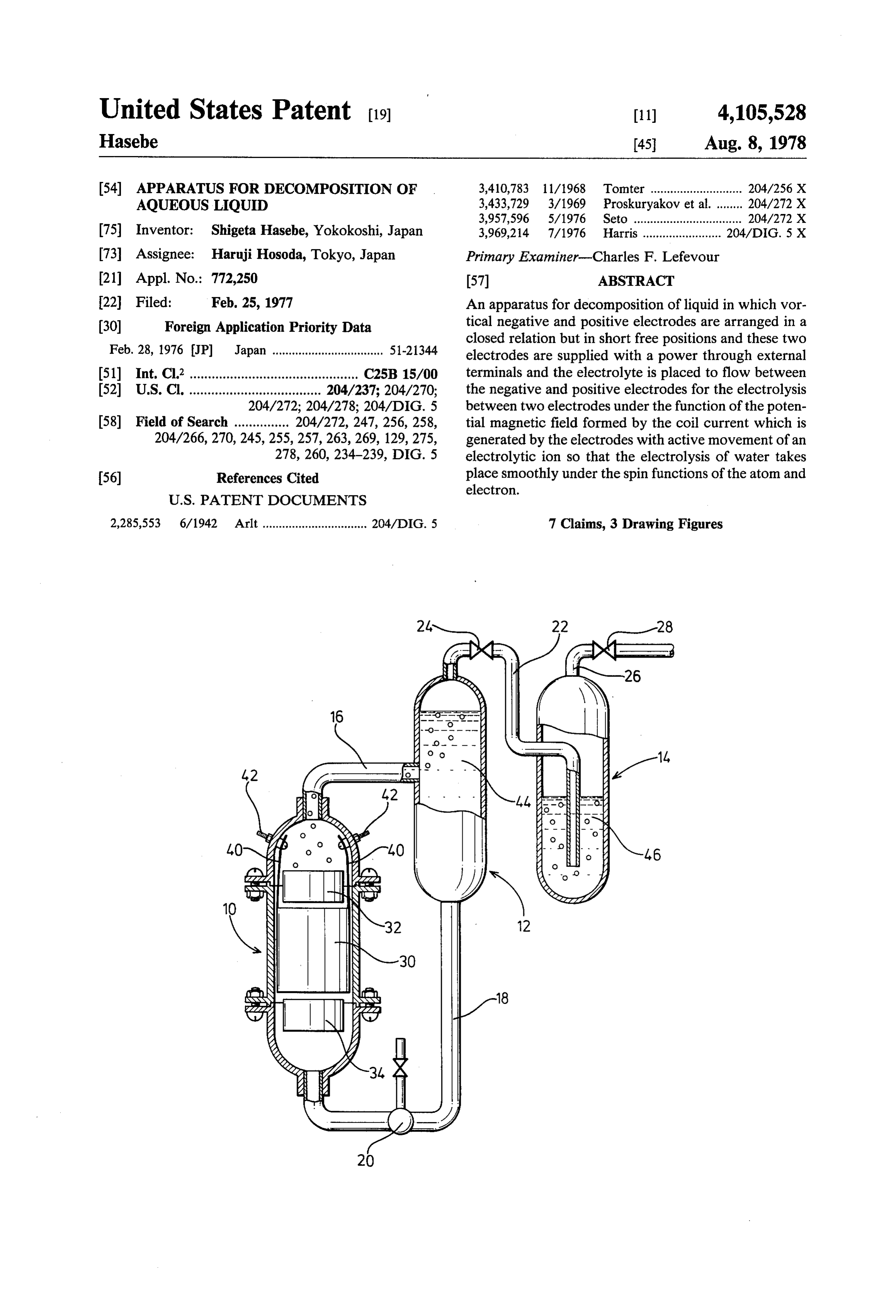
United States Patent (19) 11) 4,105,528 Hasebe 45 Aug. 8, 1978 54 APPARATUS FOR DECOMPOSITION OF 3,410,783 1 1/1968 Tomter ............................ 204/256 X AQUEOUS LIQUID 3,433,729 3/1969 Proskuryakov et al......... 204/272 X 3,957,596 5/1976 Seto ................................. 204/272 X 75 Inventor: Shigeta Hasebe, Yokokoshi, Japan 3,969,214 7/1976 Harris........................ 204/DIG. 5 X 73 Assignee: Haruji Hosoda, Tokyo, Japan Primary Examiner-Charles F. Lefevour 21 Appl. No.: 772,250 57 ABSTRACT 22 Filed: Feb. 25, 1977 An apparatus for decomposition of liquid in which vor 30 Foreign Application Priority Data tical negative and positive electrodes are arranged in a closed relation but in short free positions and these two
Feb. 28, 1976 JP Japan .................................. 51-21344 electrodes are supplied with a power through external 5ll Int. Cl’.............................................. C25B 15/00 terminals and the electrolyte is placed to flow between 52) U.S.C. .................................... 204/237; 204/270; the negative and positive electrodes for the electrolysis 204/272; 204/278; 204/DIG. 5 between two electrodes under the function of the poten 58) Field of Search ............... 204/272, 247, 256, 258, tial magnetic field formed by the coil current which is 204/266, 270, 245, 255, 257,263,269, 129, 275, generated by the electrodes with active movement of an 278, 260, 234-239, DIG. 5 electrolytic ion so that the electrolysis of water takes 56) References Cited place smoothly under the spin functions of the atom and electron.
2,285,553 6/1942 Arlt................................ 204/EDIG. 5 7 Claims, 3 Drawing Figures
Page 2
Drawing sheet — no readable text.
Page 3
Other objects and advantages of the present invention
APPARATUS FOR DECOMPOSITION OF will become apparent as the detailed description thereof
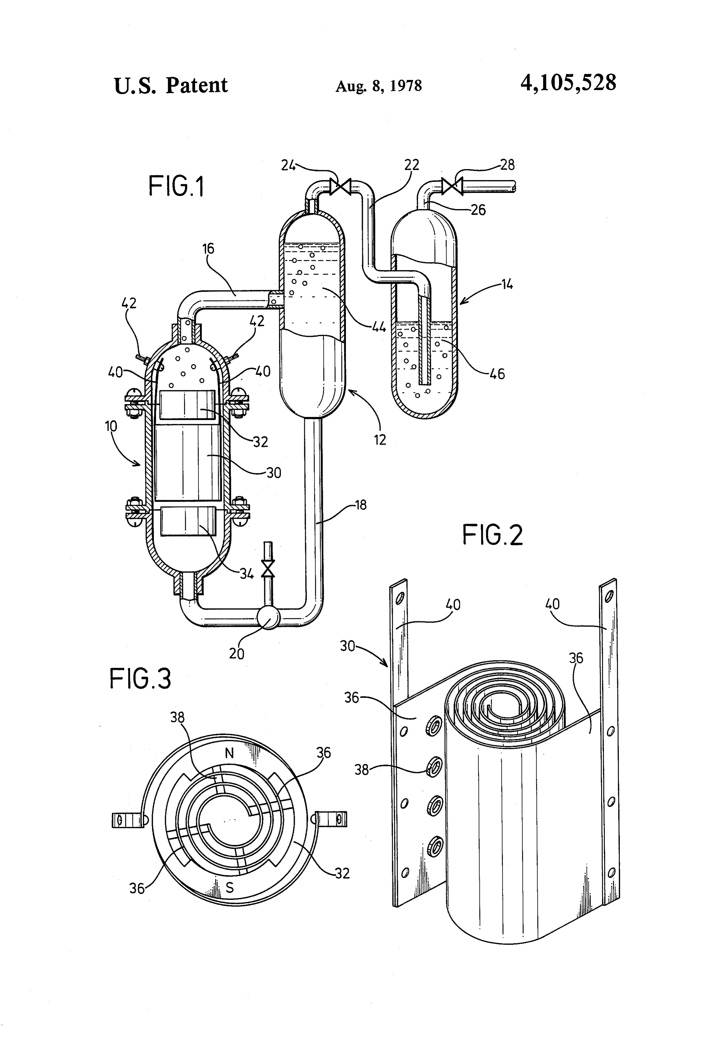
BACKGROUND AND SUMMARY OF THE BRIEF DESCRIPTION OF THE DRAWINGS INVENTION The invention will be described more in detail in the This invention relates to an apparatus for decomposi following with reference to the accompanying draw tion of liquid wherein an electrolyte in flow is subjected ings, wherein:
to an electrolysis for production of gases. FIG. 1 is a partially cross-sectional schematic eleva As is well known, water is composed of a hydrogen 10 tion of an apparatus in accordance with the invention; atom and an oxygen atom. When water is sufficiently FIG. 2 is a perspective view of electrodes arranged in magnetized, each constitutive atom is also weakly mag accordance with the invention; and
FIG. 3 is a plan view of electrodes with magnetic netized to rotate the elementary particle in a regular materials.
direction. This rotation of the elementary particle is generally called as "spin'. That is, the spin function is 15 DESCRIPTION OF THE PREFERRED caused by an electron, atomic nucleous, atom and even EMBODIMENT by the molecule. When a negative electrode is im mersed in the electrolyte (NaOH solution) for applying tionIn tankFIG. 1, an electrolytic cell 10, a gas-liquid separa 12 and a gas washing tank 14 are vertically a voltage thereto to cause the elementary particle to 20 arranged injuxtaposition with a location of the electro react with the electric field, the coupling state of the lytic cell 10 in a little lower level than the others. hydrogen with the oxygen is varied and the electrolysis These cell 10 and tanks 12, 14 are communicated with is facilitated under the function of the spin. each other through a delivery pipe 16 which communi In accordance with the present invention, vortical cates the top of the electrolytic cell 10 with the middle negative and positive electrodes are arranged in a 25 portion of the gas-liquid separation tank 12, a feed-back closed relation but in short free positions and these two pipe 18 provided with a pump 20, which communicates electrodes are supplied with a power through external the bottom portion of the gas-liquid separation tank 12 terminals and the electrolyte is placed to flow between with the bottom portion of the electrolytic cell 10, and the negative and positive electrodes. Thus, the electro a conduit 22, which is extended from the top portion of lyte is subjected to the electrolysis between two elec 30 the gas-liquid separation tank 12 through a valve 24 into trodes under the function of the potential magnetic field the bottom portion of the gas washing tank 14. To the formed by the coil current which is generated by the top portion of the gas washing tank 14 is connected a electrodes with active movement of an electrolytic ion drain pipe 26 through a valve 28.
(Nat, OH) so that the electrolysis of water takes place In the electrolytic cell 10, positive and negative vorti smoothly under the spin functions of the atom and elec 35 cal electrodes 30 of diameters as defined in accordance tron. with an internal diameter of the electrolytic cell 10 are It has been confirmed that the rate of the electrolysis arraned coaxially, and at upper and lower positions of of water according to the invented process is approxi the vortical electrode 30 are arranged magnet rings 32 mately 10 or more times (approximately 20 times on and 34 of ferrite and the like, of which positive and calculation) as that of the conventional electrolysis. negative magnetic poles are confronted therein so that a The structural design of electrolytic cell in accor magnetic field generated is orthogonal to the axis of the dance with the invented system is characterized in that electrolytic cell.
the electrolyte flowing through the supply ports pro The vortical electrodes 30 are composed of two metal vided at the lower portion of the electrolytic cell is 45 strips 36 which are wound into vortical shapes with a subjected to the potential magnetic field in the presence plurality of cylindrical insulating spacers 38 of rubber of the permanent magnet and that the electrodes for and the like interposed therebetween in attachment to electrolysis is subjected to the more potential magnetic the surface of the metal strips 36. and electric fields to obtain a sufficient spin effect. From the metal strips 36 are withdrawn lead wires 40, It is, therefore, a general object of the invention to 50 40 which are in turn connected respectively to positive or negative electrode terminals provided in the inner provide a novel apparatus for decomposition of liquid in wall of the electrolytic cell. which an electrolyte (NaOH) solution is subjected to The electrolytic cell 10 and the gas-liquid separation magnetic field to carry out an electrolysis under the tank 12 are filled with a electrolyte 44 which may be function of the spin of an element constituting water circulated by the pump 20 whereas the gas washing molecule thereby to produce a great amount of gas with 55 tank 14 is filled with a washing liquid 46 to such a pre less consumption of electric energy.
A principal object of the invention is to provide an well washed. gases gushing out of the conduit 22 is ferred level that apparatus for decomposition of liquid including a liquid circulating system for separation of gas and liquid in tionThe apparatus in accordance with the present inven may be well applicable to an electrolysis of flowing which positive and negative vortical electrodes are water for production of hydrogen gas and oxygen gas at arranged to traverse a flow path of liquid and said vorti a high efficiency. That is to say, the electrolytic cell 10 cal electrodes at their opposite ends being arranged and the gas-liquid separation tank 12 are filled with the with magnetic materials to apply a predetermined volt electrolyte 44 which is constrained by operation of the age for a liquid passing through a magnetic field by said pump 20 to flow through a magnetic field in an annular positive and negative vortical electrodes thereby to 65 path in which positive and negative magnetic poles N, S promote generation and separation of cation and anion of the magnets 32 and 34 are confronted and through with a high efficiency in production of a large quantity the metal plates 36 of the vortical electrode 30 to impart of gases by way of an electrolysis of liquid. an orientation to an electrical migration of cation and
Page 4
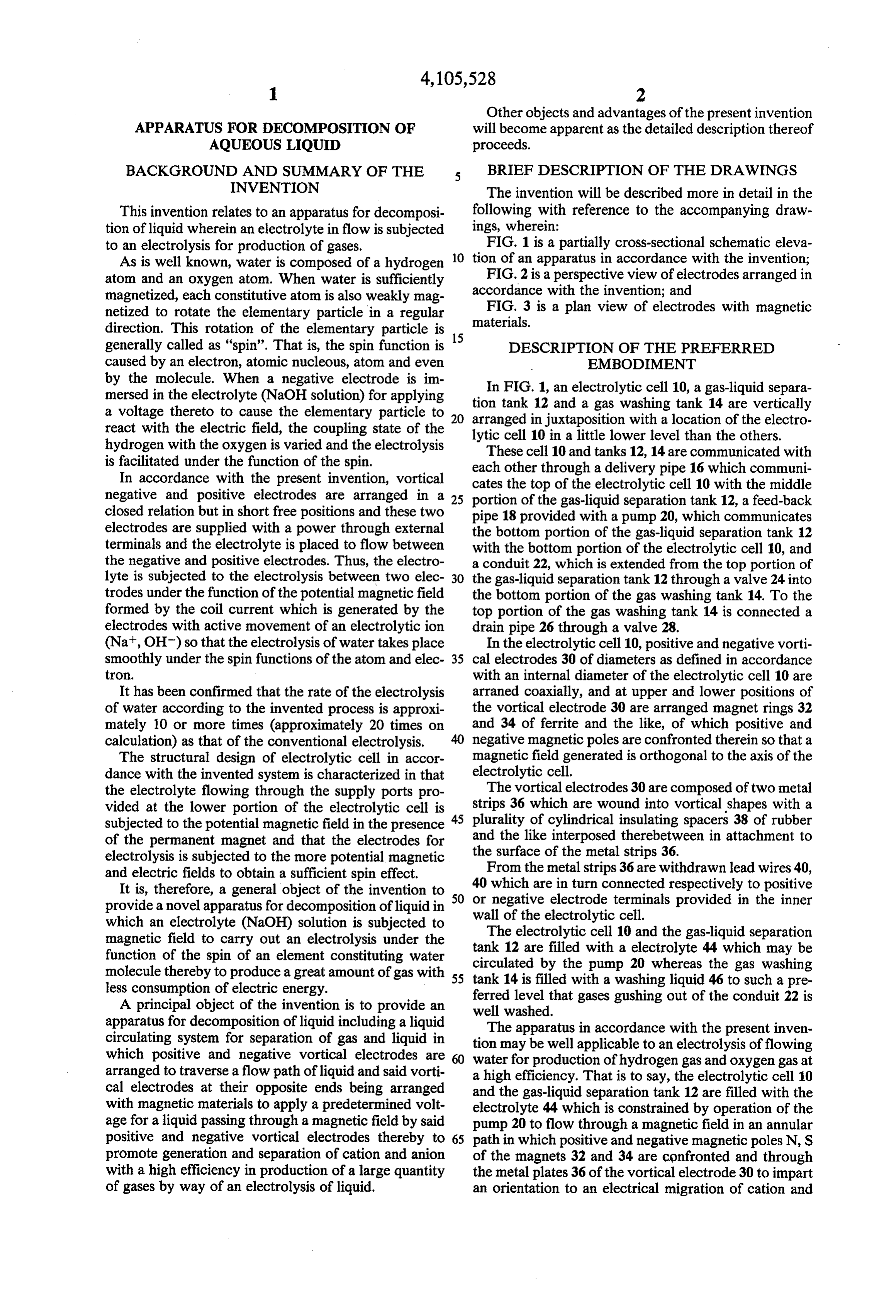
anion with increased gas separation rate and promotion -continued of electrolysis.
Especially, the flowing oxygen gas serves to facilitate Experimental Data
Gas(Mixed Gas of Hydrogen and a gasification as it has a magnetic property of variable Oxygen) 116ccasec under an influence of the magnetic field. The vortical 5 Per Coulomb (EA X i Sec)
electrodes 30 in accordance with the invention brings a Oxygen i.3 cc remarkable increasement in the electrolytic rate since a hydraulic diameter in a space between metal strips of the electrode 30 is reduced and hence the flow velocity to andThe theoretical amount of generation of hydrogen oxygen by the electrolysis in accordance with the in the space is increased so that a positive convection in the gap serves to cause turbulence and accordingly present system are as mentioned below. gasified bubbles produced by an electrolysis and at Hydrogen H - 1 gram = 11.21 (0°C 1 atm) tached to the surface of the electrode 30 are removed Oxygen O - 8 gram = 5.6l (0° C 1 atm) instantly in replacement by fresh ions. However, the experimental data have showed the The vortical construction of positive and negative 15 following facts.
metal strips alternately opposing to each other enables a desired reduction in bulk of the cell, while increasing a Per 1 Coulomb Hydrogen 2.6 cc at 20 C contacting area with the electrolyte 44 with relatively Per 1 Faraday Oxygen
Hydrogen
short migration distance of ions for promotion of gasifi Oxygen 1.3 cc x 96.540 at 125 cation. On the other hand, insulating spacers 38 inter- 20 (where 1 F = 96540 Coulomb) posed between the positive and negative metal strips 36 serves to develope desired turbulence of the electrolyte Even by correction at the room temperature of 20 C, passing through the space. the rate of generation over 20 times could be obtained. The liquid circulating system for separation of gas
Theory
permanent decomposition magnet electrode high speed potential potential magnetic decompo pump magnetic field and sition field electrolysis primary secondary spin
effect oxygen
electrolyte hydrogen and liquid requires no other driving unit except the circulation pump 20 to achieve separation of gas and 40 theAsinventionhereinbefore fully described in accordance with generation and separation of cation and liquid by utilizing differences in water heads developed anion in a flowing liquid is facilitated at a high effi among the cell 10 and the tanks 12 and 14. In other
Words, a flow of gas-liquid mixture supplied from elec ciency of gas production rate by the electrolysis. trolytic cell 10 is fed into the gas-liquid separation tank 45 tionWhile certain preferred embodiments of the inven have been illustrated by way of example in the 12 where due to the difference in buoyancy of gases and drawings liquid, gas rises and is fed into the gas washing tank 14 stood thatand particularly described, it will be under various modifications may be made in the whereas the liquid goes down and is returned again to constructions and that the invention is no way limited to the electrolytic cell 10. The washing tank 14 is filled with convenient washing liquid 46 so that gases gushing 50 theWhat embodiments shown.
I claim is:
out of conduit 22 are washed and fed into the drain pipe 1. Apparatus for the decomposition of aqueous liquid 26. Thus, the apparatus may be constructed at reduced whereby gas is formed comprising a cell, having an inlet cost without complexity.
As hereinbefore described, the magnets 32 and 34 at one end and an outlet at the other, positive and nega provide positive and negative magnetic poles N, S 55 tive inlet electrodes mounted within said cell between said and outlet connected to a source of electric cur which are confronted in the annular wall for facilitating an alignment between the cross section of the flow-path rent, said electrodes being wound about each other in Substantially coaxial helices to form a vortex transverse of the liquid and the annular portion of the magnets 32, to the flow of liquid, and magnetic means mounted with 34 and a generation of a magnetic field in a direction perpendicular to that of the liquid flow, so that the 60 said cell at each of the axial ends of said electrodes. liquid is ensured to flow in the magnetic field. 2. The apparatus according to claim 1, wherein said inlet and outlet means are at axial ends of said elec trodes.
Experimental Data 3. The apparatus according to claim 2, including a Room Temperature 20 C gas-liquid separation tank and a gas-washing tank each
Temperature of Aqueous Solution 25°C 65 vertically arranged in juxtaposition, conduit means con Humidity 43% necting the top of the cell with the mid-portion of the
Current 30A gas-liquid separation tank, a feed-back conduit connect Amount of Decomposed and Produced ing the bottom end of the gas-liquid separation tank
Page 5
with said pump, a conduit connecting the top end of the tallic material, each electrode being provided with a gas-liquid separation tank and the lower portion of the lead wire secured to the cell, and having contact means gas-washing tank, a valve inserted in said latter conduit extending through the wall thereof. and a drain pipe connected to the top end of the gas 6. The apparatus according to claim 1 including insu washing tank for exhaust of the gas. lating spaces interposed between said electrodes. 4. The apparatus according to claim 1, including a 7. The apparatus according to claim 1, wherein said pump at the inlet for feeding the liquid under pressure magnetic means comprise annular members having dia through said cell. metrically opposed positive and negative poles lying 5. The apparatus according to claim 1, wherein each orthogonal to the flow of liquid. of said electrodes is formed of at least one sheet of me 10 sk k is k k
Provenance
- Collection
- Cited prior art
- Original PDF
- patentimages.storage.googleapis.com →
- Filed
- 1977-02-25
- Pages
- 5
- Method
- pdftotext (the PDF's own text layer) + pdftoppm 300dpi page scans
- Source
- Google Patents bibliographic record
- Granted
- 1978-08-08
- Inventors
- Shigeta Hasebe
- Transcribed from
- patentimages.storage.googleapis.com →