patent · US3522162
Electrolytic reactions under influence of magnetic field
28 July 1970
Page 1 — bibliographic record
July 28, 1970 R. L. DAVIES 3,522,162
EECTROLYTIC REACTIONS UNDER INFLUENCE OF MAGNETIC FIELD
Filed Feb. 18, 1965 2 Sheets-Sheet l
AAAAWA. W. W. Wva WYAVWWWWWVY moves. Asya was awawa was saw was waw w w x
a Yar Wavyawaavasavaaravana wavvava 2as ava as awara revivasara vs rar ris %
INVENTOR
Page 2
Drawing sheet — no readable text.
Page 3
United States Patent Office 3,522,162 Patented July 28, 1970
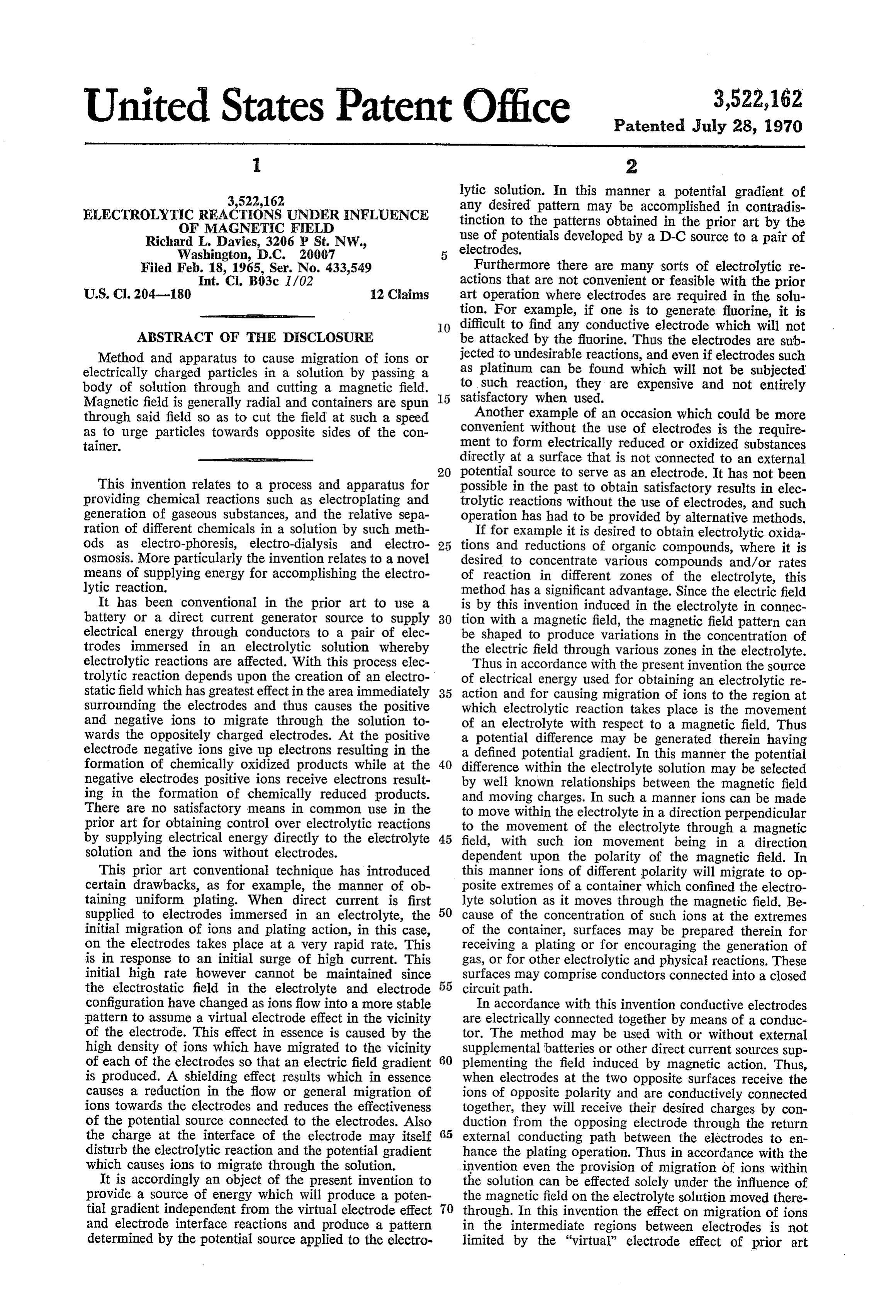
lytic solution. In this manner a potential gradient of 3,522,162 any desired pattern may be accomplished in contradis
ELECTROLYTIC REACTIONS UNDER INFLUENCE tinction to the patterns obtained in the prior art by the
OF MAGNETIC FELD
Richard L. Davies, 3206 P St. N.W., use of potentials developed by a D-C source to a pair of
Filed Feb. 18, 1965, Ser. No. 433,549 Furthermore there are many sorts of electrolytic re Int. C. B03c I/02 actions that are not convenient or feasible with the prior U.S. C. 204-180 12 Claims art operation where electrodes are required in the solu tion. For example, if one is to generate fluorine, it is
O difficult to find any conductive electrode which will not
ABSTRACT OF THE DESCLOSURE be attacked by the fluorine. Thus the electrodes are sub Method and apparatus to cause migration of ions or jected to undesirable reactions, and even if electrodes such electrically charged particles in a solution by passing a as platinum can be found which will not be subjected body of solution through and cutting a magnetic field. to such reaction, they are expensive and not entirely Magnetic field is generally radial and containers are spun satisfactory when used.
through said field so as to cut the field at such a speed Another example of an occasion which could be more as to urge particles towards opposite sides of the con convenient without the use of electrodes is the require tainer. ment to form electrically reduced or oxidized substances -aumaraeses eccamarm directly at a surface that is not connected to an external potential source to serve as an electrode. It has not been
This invention relates to a process and apparatus for possible in the past to obtain satisfactory results in elec providing chemical reactions such as electroplating and trolytic reactions without the use of electrodes, and such generation of gaseous substances, and the relative sepa operation has had to be provided by alternative methods. ration of different chemicals in a solution by such meth If for example it is desired to obtain electrolytic oxida ods as electro-phoresis, electro-dialysis and electro 25 tions and reductions of organic compounds, where it is osmosis. More particularly the invention relates to a novel desired to concentrate various compounds and/or rates means of supplying energy for accomplishing the electro of reaction in different zones of the electrolyte, this lytic reaction. method has a significant advantage. Since the electric field It has been conventional in the prior art to use a is by this invention induced in the electrolyte in connec battery or a direct current generator source to supply 30 tion with a magnetic field, the magnetic field pattern can electrical energy through conductors to a pair of elec be shaped to produce variations in the concentration of trodes immersed in an electrolytic solution whereby the electric field through various zones in the electrolyte. electrolytic reactions are affected. With this process elec Thus in accordance with the present invention the source trolytic reaction depends upon the creation of an electro of electrical energy used for obtaining an electrolytic re static field which has greatest effect in the area immediately 35 action and for causing migration of ions to the region at surrounding the electrodes and thus causes the positive which electrolytic reaction takes place is the movement and negative ions to migrate through the solution to of an electrolyte with respect to a magnetic field. Thus wards the oppositely charged electrodes. At the positive a potential difference may be generated therein having electrode negative ions give up electrons resulting in the a defined potential gradient. In this manner the potential formation of chemically oxidized products while at the 40 difference within the electrolyte solution may be selected negative electrodes positive ions receive electrons result by well known relationships between the magnetic field ing in the formation of chemically reduced products. and moving charges. In such a manner ions can be made There are no satisfactory means in common use in the to move within the electrolyte in a direction perpendicular prior art for obtaining control over electrolytic reactions to the movement of the electrolyte through a magnetic by supplying electrical energy directly to the electrolyte 45 field, with such ion movement being in a direction solution and the ions without electrodes. dependent upon the polarity of the magnetic field. In This prior art conventional technique has introduced this manner ions of different polarity will migrate to op certain drawbacks, as for example, the manner of ob posite extremes of a container which confined the electro taining uniform plating. When direct current is first lyte solution as it moves through the magnetic field. Be supplied to electrodes immersed in an electrolyte, the 50 cause of the concentration of such ions at the extremes initial migration of ions and plating action, in this case, of the container, surfaces may be prepared therein for on the electrodes takes place at a very rapid rate. This receiving a plating or for encouraging the generation of is in response to an initial surge of high current. This gas, or for other electrolytic and physical reactions. These initial high rate however cannot be maintained since surfaces may comprise conductors connected into a closed the electrostatic field in the electrolyte and electrode 55 circuit path.
configuration have changed as ions flow into a more stable In accordance with this invention conductive electrodes pattern to assume a virtual electrode effect in the vicinity are electrically connected together by means of a conduc of the electrode. This effect in essence is caused by the tor. The method may be used with or without external high density of ions which have migrated to the vicinity supplemental batteries or other direct current sources sup of each of the electrodes so that an electric field gradient 60 plementing the field induced by magnetic action. Thus, is produced. A shielding effect results which in essence when electrodes at the two opposite surfaces receive the causes a reduction in the flow or general migration of ions of opposite polarity and are conductively connected ions towards the electrodes and reduces the effectiveness together, they will receive their desired charges by con of the potential source connected to the electrodes. Also duction from the opposing electrode through the return the charge at the interface of the electrode may itself external conducting path between the electrodes to en disturb the electrolytic reaction and the potential gradient hance the plating operation. Thus in accordance with the which causes ions to migrate through the solution. invention even the provision of migration of ions within It is accordingly an object of the present invention to the solution can be effected solely under the influence of provide a source of energy which will produce a poten the magnetic field on the electrolyte solution moved there tial gradient independent from the virtual electrode effect 70 through. In this invention the effect on migration of ions and electrode interface reactions and produce a pattern in the intermediate regions between electrodes is not determined by the potential source applied to the electro limited by the "virtual" electrode effect of prior art
Page 4
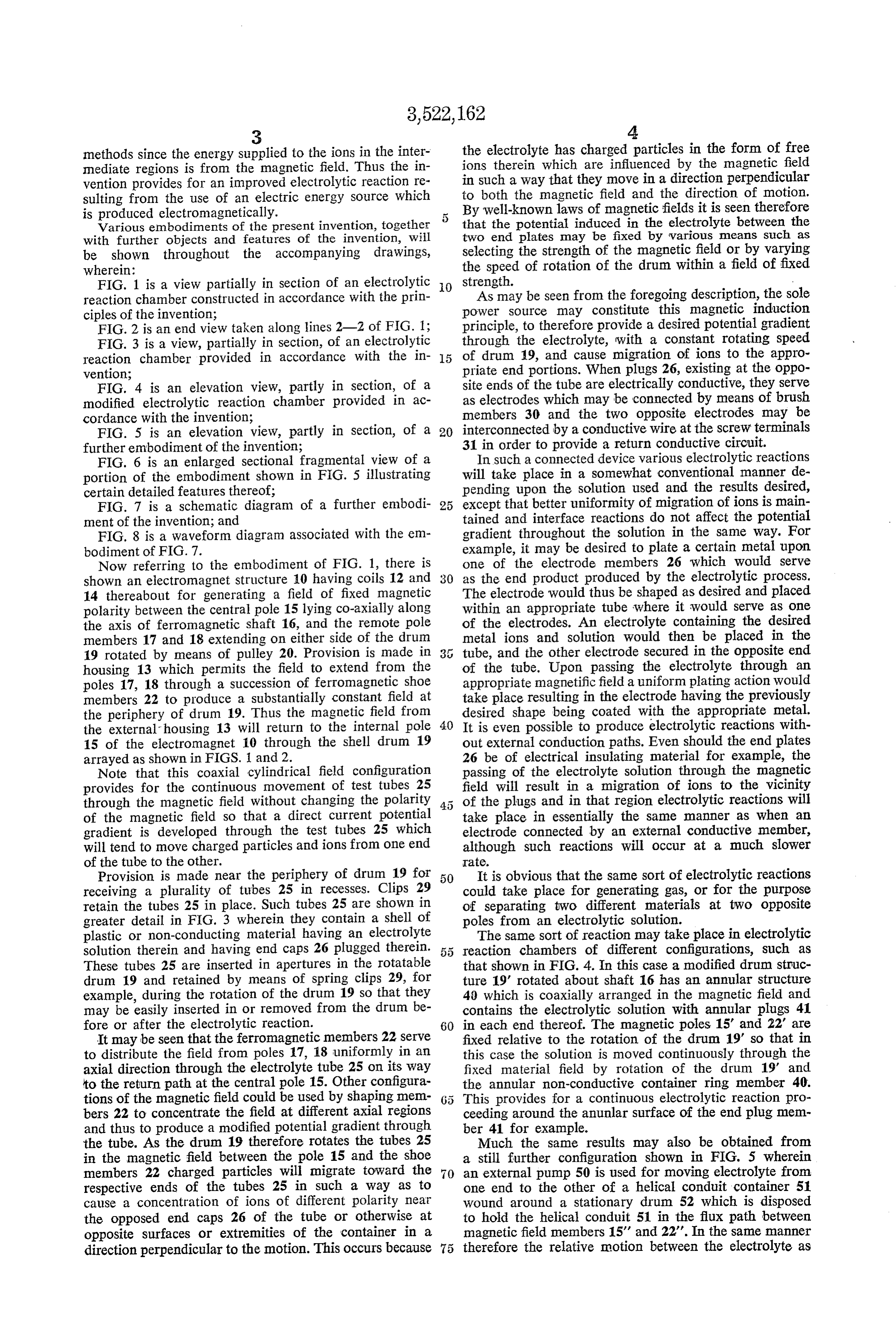
methods since the energy supplied to the ions in the inter the electrolyte has charged particles in the form of free mediate regions is from the magnetic field. Thus the in ions therein which are influenced by the magnetic field vention provides for an improved electrolytic reaction re in such a way that they move in a direction perpendicular sulting from the use of an electric energy source which to both the magnetic field and the direction of motion.
By well-known laws of magnetic fields it is seen therefore
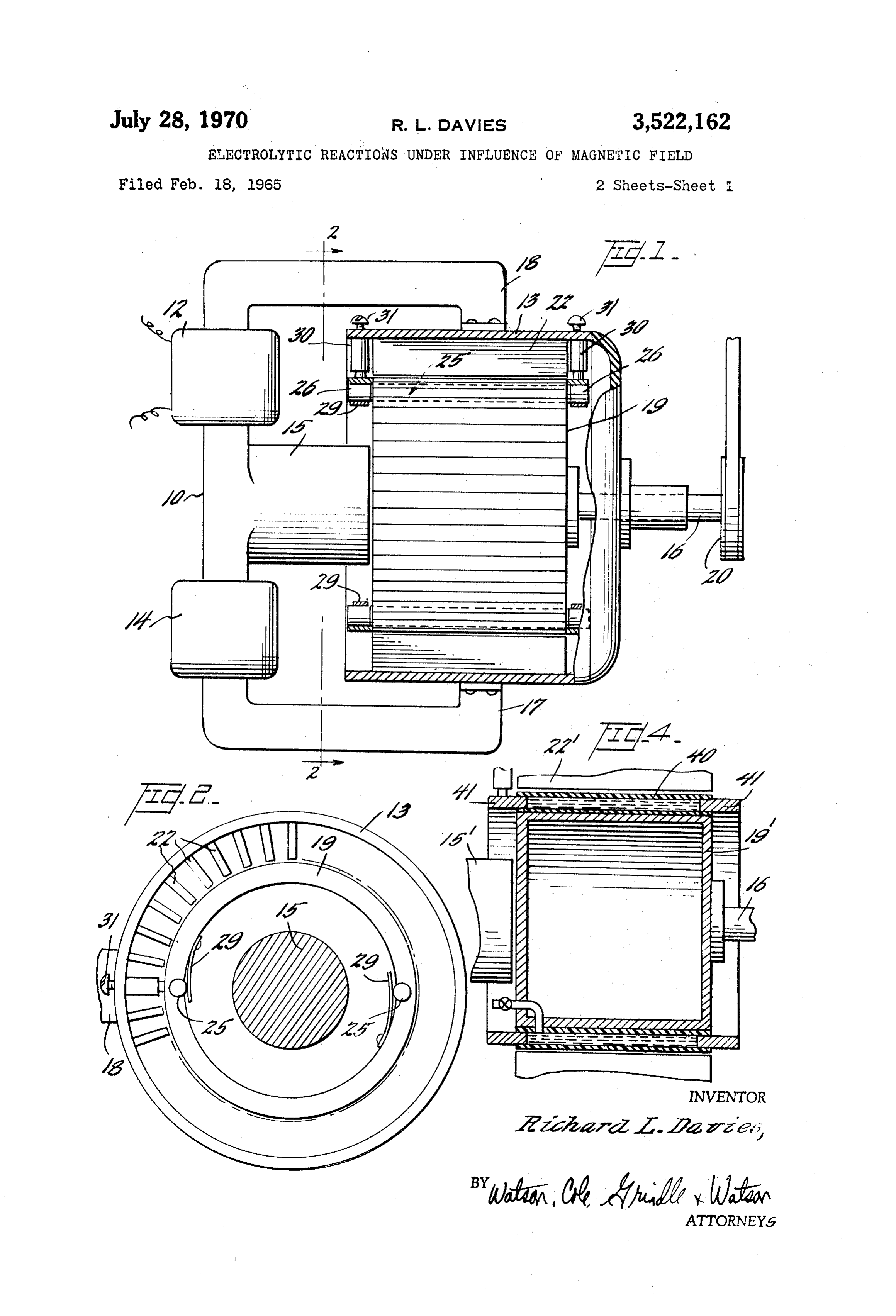
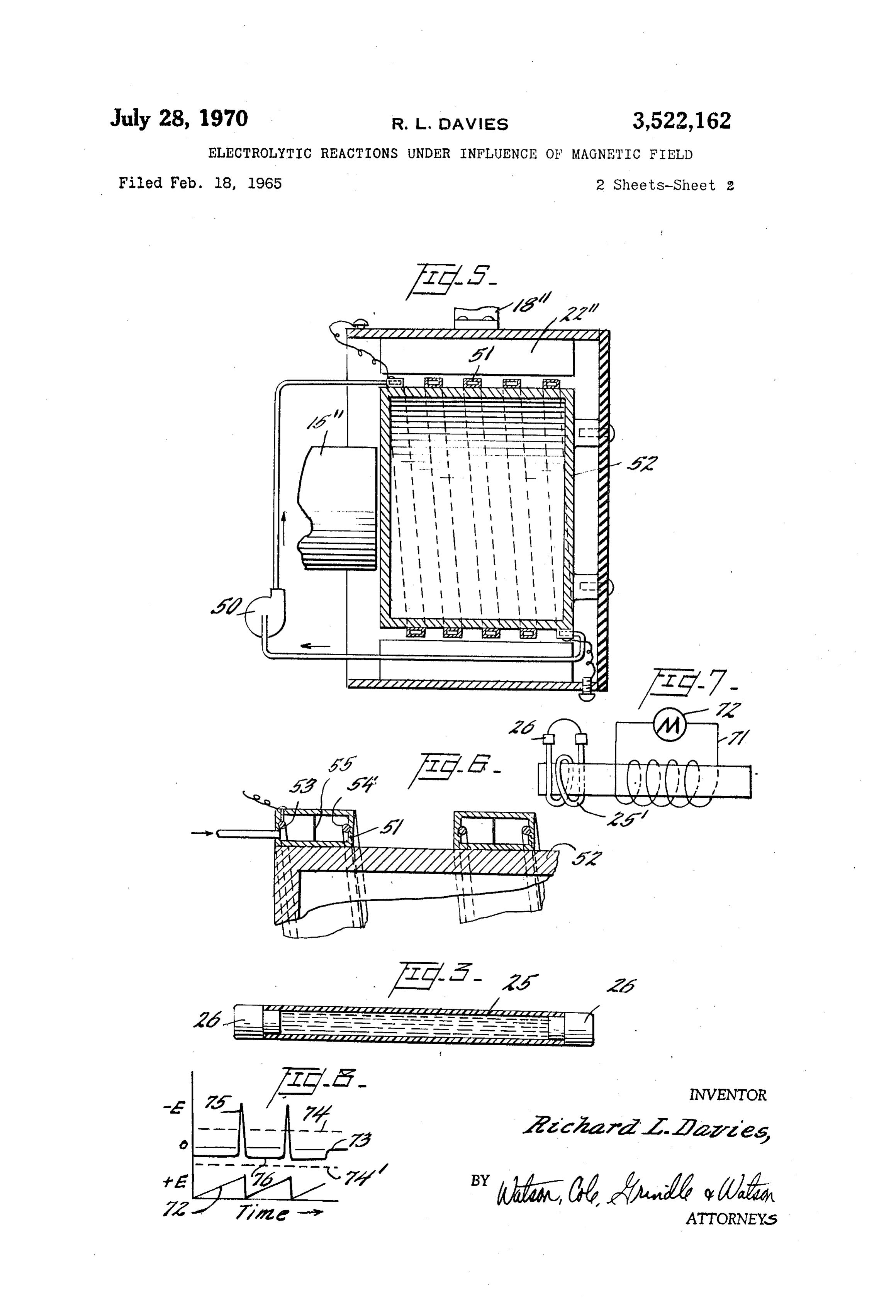
Various embodiments of the present invention, together that the potential induced in the electrolyte between the with further objects and features of the invention, will two end plates may be fixed by various means such as be shown throughout the accompanying drawings, selecting the strength of the magnetic field or by varying wherein: the speed of rotation of the drum within a field of fixed FIG. 1 is a view partially in section of an electrolytic O strength.
reaction chamber constructed in accordance with the prin As may be seen from the foregoing description, the sole ciples of the invention; power source may constitute this magnetic induction FIG. 2 is an end view taken along lines 2-2 of FIG. 1; principle, to therefore provide a desired potential gradient FIG. 3 is a view, partially in section, of an electrolytic through the electrolyte, with a constant rotating speed reaction chamber provided in accordance with the in 5 of drum 19, and cause migration of ions to the appro vention; priate end portions. When plugs 26, existing at the oppo FIG. 4 is an elevation view, partly in section, of a site ends of the tube are electrically conductive, they serve modified electrolytic reaction chamber provided in ac as electrodes which may be connected by means of brush cordance with the invention; members 30 and the two opposite electrodes may be FIG. 5 is an elevation view, partly in section, of a 20 interconnected by a conductive wire at the screw terminals further embodiment of the invention; 31 in order to provide a return conductive circuit. FIG. 6 is an enlarged sectional fragmental view of a In such a connected device various electrolytic reactions portion of the embodiment shown in FiG. 5 illustrating will take place in a somewhat conventional manner de certain detailed features thereof; pending upon the solution used and the results desired, FIG. 7 is a schematic diagram of a further embodi 25 except that better uniformity of migration of ions is main ment of the invention; and tained and interface reactions do not affect the potential FIG. 8 is a waveform diagram associated with the em gradient throughout the solution in the same way. For bodiment of FIG. 7. example, it may be desired to plate a certain metal upon Now referring to the embodiment of FIG. 1, there is one of the electrode members 26 which would serve shown an electromagnet structure 10 having coils 12 and 30 as the end product produced by the electrolytic process. 14 thereabout for generating a field of fixed magnetic The electrode would thus be shaped as desired and placed polarity between the central pole 15 lying co-axially along within an appropriate tube where it would serve as one the axis of ferromagnetic shaft 16, and the remote pole of the electrodes. An electrolyte containing the desired members 17 and 18 extending on either side of the drum metal ions and solution would then be placed in the 19 rotated by means of pulley 20. Provision is made in tube, and the other electrode secured in the opposite end housing 13 which permits the field to extend from the of the tube. Upon passing the electrolyte through an poles 17, 18 through a succession of ferromagnetic shoe appropriate magnetific field a uniform plating action would members 22 to produce a substantially constant field at take place resulting in the electrode having the previously the periphery of drum 19. Thus the magnetic field from desired shape being coated with the appropriate metal. the external housing 13 will return to the internal pole 40 It is even possible to produce electrolytic reactions with 15 of the electromagnet 10 through the shell drum 19 out external conduction paths. Even should the end plates arrayed as shown in FIGS. 1 and 2. 26 be of electrical insulating material for example, the Note that this coaxial cylindrical field configuration passing of the electrolyte solution through the magnetic provides for the continuous movement of test tubes 25 field will result in a migration of ions to the vicinity through the magnetic field without changing the polarity of the plugs and in that region electrolytic reactions will of the magnetic field so that a direct current potential take place in essentially the same manner as when an gradient is developed through the test tubes 25 which electrode connected by an external conductive member, will tend to move charged particles and ions from one end although such reactions will occur at a much slower of the tube to the other. irate.
Provision is made near the periphery of drum 19 for 50 It is obvious that the same sort of electrolytic reactions receiving a plurality of tubes 25 in recesses. Clips 29 could take place for generating gas, or for the purpose retain the tubes 25 in place. Such tubes 25 are shown in of separating two different materials at two opposite greater detail in FIG. 3 wherein they contain a shell of poles from an electrolytic solution. plastic or non-conducting material having an electrolyte The same sort of reaction may take place in electrolytic solution therein and having end caps 26 plugged therein. reaction chambers of different configurations, such as These tubes 25 are inserted in apertures in the rotatable that shown in FIG. 4. In this case a modified drum struc drum 19 and retained by means of spring clips 29, for ture 19' rotated about shaft 16 has an annular structure example, during the rotation of the drum 19 so that they 40 which is coaxially arranged in the magnetic field and may be easily inserted in or removed from the drum be contains the electrolytic solution with annular plugs 41 fore or after the electrolytic reaction. 60 in each end thereof. The magnetic poles 15' and 22' are It may be seen that the ferromagnetic members 22 serve fixed relative to the rotation of the drum 19' so that in to distribute the field from poles 17, 18 uniformly in an this case the Solution is moved continuously through the axial direction through the electrolyte tube 25 on its way fixed material field by rotation of the drum 19' and to the return path at the central pole 15. Other configura the annular non-conductive container ring member 40. tions of the magnetic field could be used by shaping mem This provides for a continuous electrolytic reaction pro bers 22 to concentrate the field at different axial regions ceeding around the anunlar surface of the end plug mem and thus to produce a modified potential gradient through ber 41 for example.
the tube. As the drum 19 therefore rotates the tubes 25 Much the same results may also be obtained from in the magnetic field between the pole 15 and the shoe a still further configuration shown in FIG. 5 wherein members 22 charged particles will migrate toward the an external pump 50 is used for moving electrolyte from respective ends of the tubes 25 in such a way as to one end to the other of a helical conduit container 51 cause a concentration of ions of different polarity near wound around a stationary drum 52 which is disposed the opposed end caps 26 of the tube or otherwise at to hold the helical conduit 51 in the flux path between opposite surfaces or extremities of the container in a magnetic field members 15' and 22'. In the same manner direction perpendicular to the motion. This occurs because 75 therefore the relative motion between the electrolyte as
Page 5
it is pumped through the helical conduit and the fixed source of direct current such as an external battery con magnetic field will provide an electric field which forces nected to the electrodes for achieving electroplating in the ions laterally toward either side of the helical conduit the conventional way, the voltage across the electrodes as may be seen in more detail from FIG. 6 where con necessary to maintain the electroplating process will in ductors 53 and 54 are respectively placed as electrodes, if 5 crease rather than decrease as polarization occurs. desired. It is additionally possible in this particular em Thus it is clear that the presently described novel bodiment to provide for a selective pumping of the mode of operation provides unique means and methods materials through the helical path by providing diaphragm in separation processes by causing relative migration of 55 intermediate helical conduit 51 in such a way that charged bodies and solutions to conduct chemical reac although ions may freely pass through the diaphragm 55, O tions and physical separations, i.e., electrolysis, electro the solution being passed longitudinally through the con phoresis, electro-dialysis, and electro-osmosis, which may duit by the pump 50 will tend to remain segregated on be used in many instances when conventional electrolytic either side of the diaphragm surface. In such a con reactions and physical separations with a current ex figuration two pumping paths could be used for the two ternally applied through electrodes is not satisfactory. segregated solutions. Having therefore described the present invention, its The configuration of FIG. 7 uses the foregoing prin mode of operation, and several embodiments thereof in ciple of inducing ion motion by influence of a magnetic detail, those features believed descriptive of the invention field. Thus the electrolyte in tube 25' has free ions in and its nature are defined with particularity in the follow a semi-mobile state, that can be moved once they have ing claims.
a force exerted which exceeds friction and viscosity which 20 What is claimed is:
holds them in place. Thus when primary winding 71 is 1. Apparatus for causing migration of particles selected wound with the electrolyte in tube 25 serving as a from the group consisting of ions and electrically charged secondary winding, the primary winding generates a poten particles suspended in a solution by passing said solution tial difference within the electrolyte in the tube 25' to through a magnetic field comprising in combination cause the ion migration toward the respective ends of 25 means for generating in a confined fixed area a magnetic the tube of electrolyte when a change in rate of current field which is generally radial with respect to a fixed flow exists in the primary. axis, container means comprising at least one electrically Assume the sawtooth current generator 72 of FIG. 7 non-conducting container for confining said solution is connected to coil 71, and generates the pulse wave within said magnetic field, electrically conductive means form 75-76 above and below the neutral line 73 shown 30 on opposite sides of said container means for contact in FIG. 8, which represents the potential exerted in tube with said solution and electrically connecting the opposite 25 by action of the magnetic field. Thus whenever the sides of said solution, and means for rotating said mag voltage waveform 75 exceeds the potential 74 it will netic field and said solution in said container with respect cause ions to move against the inertia or viscosity of the to each other about said axis whereby said magnetic field electrolyte tending to hold the ions in place. By applica is cut by said solution and said particles in said solution tion of the sawtooth, voltage 76 will be kept below a are urged towards the opposite sides of said container threshold value to cause motion of ions mainly in one eaaS.
direction, rather than equal oscillation back and forth. 2. Apparatus as defined in claim 1 wherein said elec Thus, essentially the same result may be obtained in 4) trically conductive means comprises conductors on op processing chemicals with an individual electric field as posite sides of said container means and a conductive in the other configuration. circuit external to the electrolyte coupling the conductors It is also to be understood in accordance with the together.
teachings of this invention that various other configura 3. Apparatus as defined in claim 1 wherein the mag tions and embodiments utilizing the relative motion of an netic field is in a coaxial cylindrical configuration and electrolytic solution with the lines of flux of a magnetic 45 said container means comprises a plurality of containers field may be used, and thereby may be within the scope (mounted on said rotary member to be moved through of this invention which is defined in the accompanying the field.
claims. 4. Apparatus as defined in claim 1 wherein the mag It is apparent from the foregoing specification that netic field is in a coaxial cylindrical configuration and there is provided herewith a form of electrolytic reaction 50 the container means comprises a cylinder container co which provides improved results over those methods of axially inserted in said field for rotation. electrolytic reaction in the prior art which depended upon 5. Apparatus as defined in claim 1 wherein the con a source of direct current supplied externally to a pair tainer means is stationary within said field and said of electrodes as the sole energy source. Although it is rotating means comprises pumping means for pumping to be recognized that the present invention may be used the solution through said container means. for. various types of electrolytic reactions, the following 6. Apparatus for causing migration of particles se plating procedure, which has been accomplished by the lected from the group consisting of ions and electrically present method, is typical of those that may be repro charged particles suspended in a solution by passing said duced with improved results. Considering the embodi solution through a magnetic field comprising in combina ment of FIGS. 1, 2 and 3, a one-quarter inch inside 60 tion means for generating a magnetic field which is gen diameter plastic tube three and three-quarters inches long erally radial with respect to a fixed axis, container means was used in a slot in the periphery of a five and one-half for confining said solution within said magnetic field, inch diameter drum revolving at a speed of twenty-seven said container means comprising a spiral pipe arranged hundred revolutions per minute. The electrolyte was about said fixed axis, electrically conductive means on a saturated stannous chloride solution with a suspension 65 opposite sides of said container means for contact with of the same, and the plugs at each end of the tube were said solution and electrically connecting the opposite copper. In this manner of rotating the solution through sides of said solution, and means for moving said mag the magnetic field, one end plug became coated with netic field and said solution in said spiral pipe with metallic tin. respect to each other about said axis whereby said mag It was noted that when the voltage measured between 70 netic field is cut by said solution and said particles in the two end terminals was monitored that the voltage said solution are urged towards the opposite sides of decreased during the five minute run exemplified from said container means.
a starting voltage of .52 volt to a terminal voltage of 7. A process for causing migration of particles selected 41 volt. This demonstrates another outstanding feature from the group consisting of ions and electrically charged of the current invention, since when using an external 75 particles suspended in a solution of electrolyte compris
Page 6
ing generating in a fixed area a magnetic field which is 12. A process as claimed in claim 7 wherein said mag generally radial with respect to a fixed axis and rotating netic field is maintained stationary and said body of said magnetic field and at least one body of Said solution, solution is rotated through said stationary magnetic field. while opposite sides of said body of Solution are elec References Cited trically connected, with respect to each other about said fixed axis with said body of solution passing through and UNITED STATES PATENTS cutting said magnetic field, said rotating being at such speed and continuously to cause said particles in said 2,842,490 7/1958 Friel - - - - - - - 204-156
solution to be urged towards said opposite sides of Said 3,356,601 12/1967 Inoue -------------- 204-156 body of solution. O
8. A process as claimed in claim 7 comprising gener 3,368,968 2/1968 Ruskin -------------- 210-42 ating in a fixed area a magnetic field in a coaxial cylindri FOREIGN PATENTS cal configuration with respect to said fixed axis.
9. A process as claimed in claim 7 comprising causing 852,733 11/1960 Great Britain. a plurality of bodies of said solution to rotate about said 5 OTHER REFERENCES fixed axis.
10. A process for causing migration of particles se Ellis: "Fresh Water From the Ocean' (1954), pp. lected from the group consisting of ions and electrically 40-43 and 62-65.
charged particles suspended in a solution of electrolyte Nernst: "Theoretical Chemistry” (1895), pp. 320 and comprising generating in a fixed area a magnetic field 20 321. i which is generally radial with respect to a fixed axis and Robinson et al.: "Electrolyte Solutions,' 2nd ed., 1959, causing a body of said solution while opposite sides of pp. 118 and 119.
said body of solution are electrically connected to move Hopkins: "Expr. Electrochem...," 1905, pp. 54-61. along a spiral path about said axis through said generally radial magnetic field at such speed and continuously 25 JOHN H. MACK, Primary Examiner to cause said particles in said solution to be urged towards A. C. PRESCOTT, Assistant Examiner said opposite sides of said body of solution.
11. Apparatus as defined in claim 1 wherein said means U.S. Cl. X.R.
for generating a magnetic field is stationary and said rotating means rotates said container means and solution so 204-149, 155, 156; 210-42, 222 contained therein through said magnetic field.
Provenance
- Collection
- Cited prior art
- Original PDF
- patentimages.storage.googleapis.com →
- Filed
- 1965-02-18
- Pages
- 6
- Method
- pdftotext (the PDF's own text layer) + pdftoppm 300dpi page scans
- Source
- Google Patents bibliographic record
- Granted
- 1970-07-28
- Inventors
- Richard L Davies; RICHARD L DAVIES
- Transcribed from
- patentimages.storage.googleapis.com →