patent · US4285389
Thermal energy storage apparatus
25 August 1981
Page 1 — bibliographic record
United States Patent (19) 11 4,285,389 Horton 45 Aug. 25, 1981
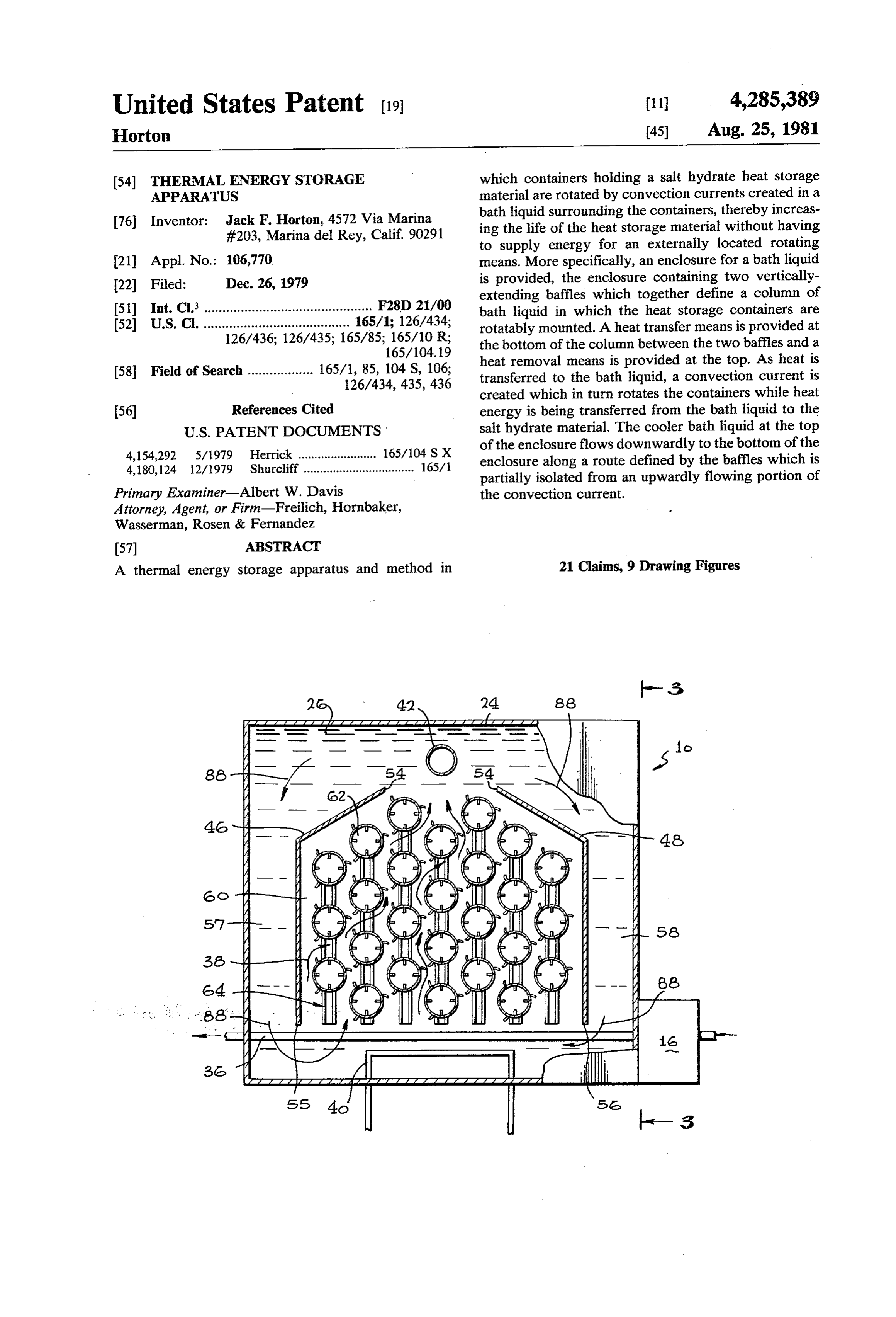
(54) THERMAL ENERGY STORAGE which containers holding a salt hydrate heat storage APPARATUS material are rotated by convection currents created in a bath liquid surrounding the containers, thereby increas 76 Inventor: Jack F. Horton, 4572 Via Marina ing the life of the heat storage material without having #203, Marina del Rey, Calif. 90291 to supply energy for an externally located rotating 21 Appl. No.: 106,770 means. More specifically, an enclosure for a bath liquid 22 Filed: Dec. 26, 1979 is provided, the enclosure containing two vertically extending baffles which together define a column of 51) Int. Cl. .............................................. F28D 21/00 bath liquid in which the heat storage containers are 52) U.S.C. ........................................ 165/1; 126/434; rotatably mounted. A heat transfer means is provided at 126/436; 126/435; 165/85; 165/10 R; the bottom of the column between the two baffles and a 165/104.19 heat removal means is provided at the top. As heat is 58 Field of Search .................. 165/1, 85, 104 S, 106; transferred to the bath liquid, a convection current is 126/434, 435, 436 created which in turn rotates the containers while heat 56) References Cited energy is being transferred from the bath liquid to the
4,154,292 5/1979 Herrick ........................ 165/104 S X of the enclosure flows downwardly to the bottom of the 4,180,124 12/1979 Shurcliff .................................. 165/ enclosure along a route defined by the baffles which is partially isolated from an upwardly flowing portion of
Primary Examiner-Albert W. Davis the convection current.
Attorney, Agent, or Firm-Freilich, Hornbaker,
Wasserman, Rosen & Fernandez
A thermal energy storage apparatus and method in 21 Claims, 9 Drawing Figures
/ N7 a 6
55 4 as
Page 2
Drawing sheet — no readable text.
Page 3
Drawing sheet — no readable text.
Page 4
Drawing sheet — no readable text.
Page 5
nally-extending tube whose outer surface is configured
THERMAL ENERGY STOERAGE APPARATUS so that a rotating moment is applied to the container as the convection current flows. In one embodiment of the
SUMMARY OF THE INVENTION invention, the outer surface is formed in the shape of The invention provides a thermal energy storage longitudinally-extending protrusions or ridges which apparatus in which at least one rotatably mounted con are angled with respect to the surface of the container tainer holding a heat storage material is located in a so that equal flow on each side of the container imparts moving portion of a convection current created within unequal moments to the container. In another embodi ment of the invention, the outer surface of the container a bath liquid by heat being added to the bath liquid 10 forms longitudinally-extending grooves or notches below the container. Baffle means are provided so that upwardly and downwardly moving portions of the which are also configured so that equal current flow on convection current can be partially isolated, thus mini each side of the container imparts unequal moments to mizing interference and mixing of the two convection the container. Use of a thermal energy storage appara current portions. Means are provided for removing heat 15 tus provided by the invention is disclosed in conjunc from the top of the bath liquid. Both bath liquid and tion with both a solar collector and a thermal radiator. heat storage material containers are chosen so that the In a heating or solar energy collection application, a specific gravity of the bath material is only slightly salt hydrate having a transition point between hydrated above that of the containers and their associated heat and unhydrated crystal states of about 95° F. is used, storage material. The outer surface of each container is one example of such a salt hydrate being sodium sulfate configured so that flow of the convection current inter (Na2SO4.10H2O). The sodium sulfate and its associated acting with the container surface causes the container to container are chosen to have a specific gravity of ap rotate. Thus, heat current, and the other having elon proximately 1.2, and a heat transfer bath of anhydrous gated notches which provide resistance to the flowing calcium chloride (CaCl 30%–70% water) is chosen to convection current. The thermal storage apparatus pro 25 have a specific gravity of about 1.3. In a cooling appli vided by the invention can be used in conjunction with cation such as an air conditioning system, a thermal both heating and air conditioning systems. energy radiator is used for removing heat from the FIELD OF THE INVENTION thermal energy storage apparatus at night, the heat storage material having a transition point between hy
This invention relates to energy storage systems and 30 drated and unhydrated crystal states of approximately more particularly to methods and apparatus for storing 57 F. An example of such a heat storage material energy in the form of heat. would be sodium hydroxide (NaOH.3H2O). In this BACKGROUND OF THE INVENTION application, heat is removed from the top of the thermal energy storage apparatus by a thermal energy radiator,
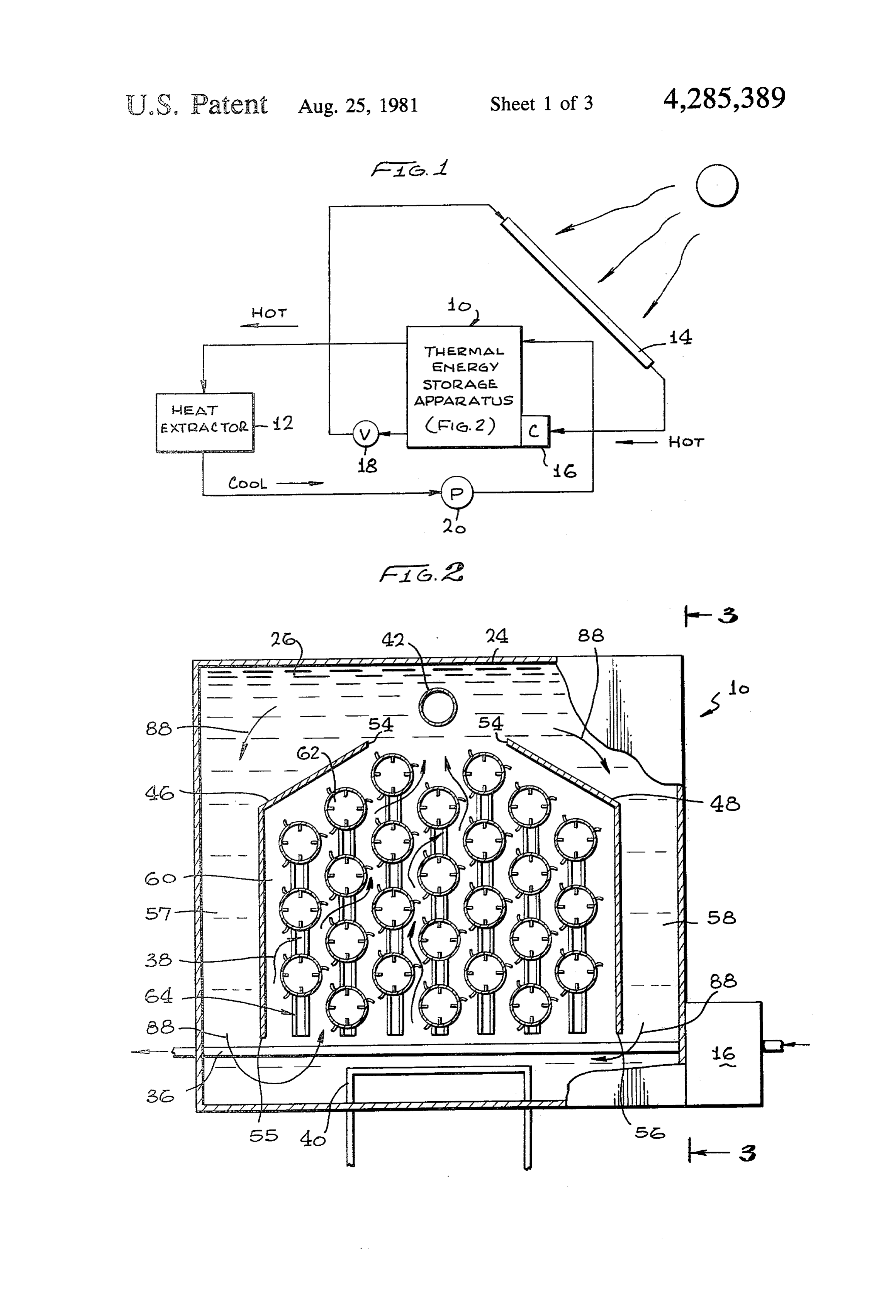
The need for an efficient thermal energy storage and it is added to the bottom of the thermal pile by a means in a solar energy or any other heat energy collec 35 flowing fluid to be cooled. tion system in which thermal energy is to be stored and subsequently recovered for use has long been recog BRIEF DESCRIPTION OF THE DRAWINGS nized. Water and stones have been used successfully but FIG. 1 is a flow diagram showing the thermal energy require large storage areas because of their low heat storage apparatus provided by the invention used in capacities. Salt hydrates because of their high heat ca 40 pacity at the transition point between hydrated and conjunction with a solar energy collector; unhydrated crystal states provide an excellent heat stor energy storage elevated,
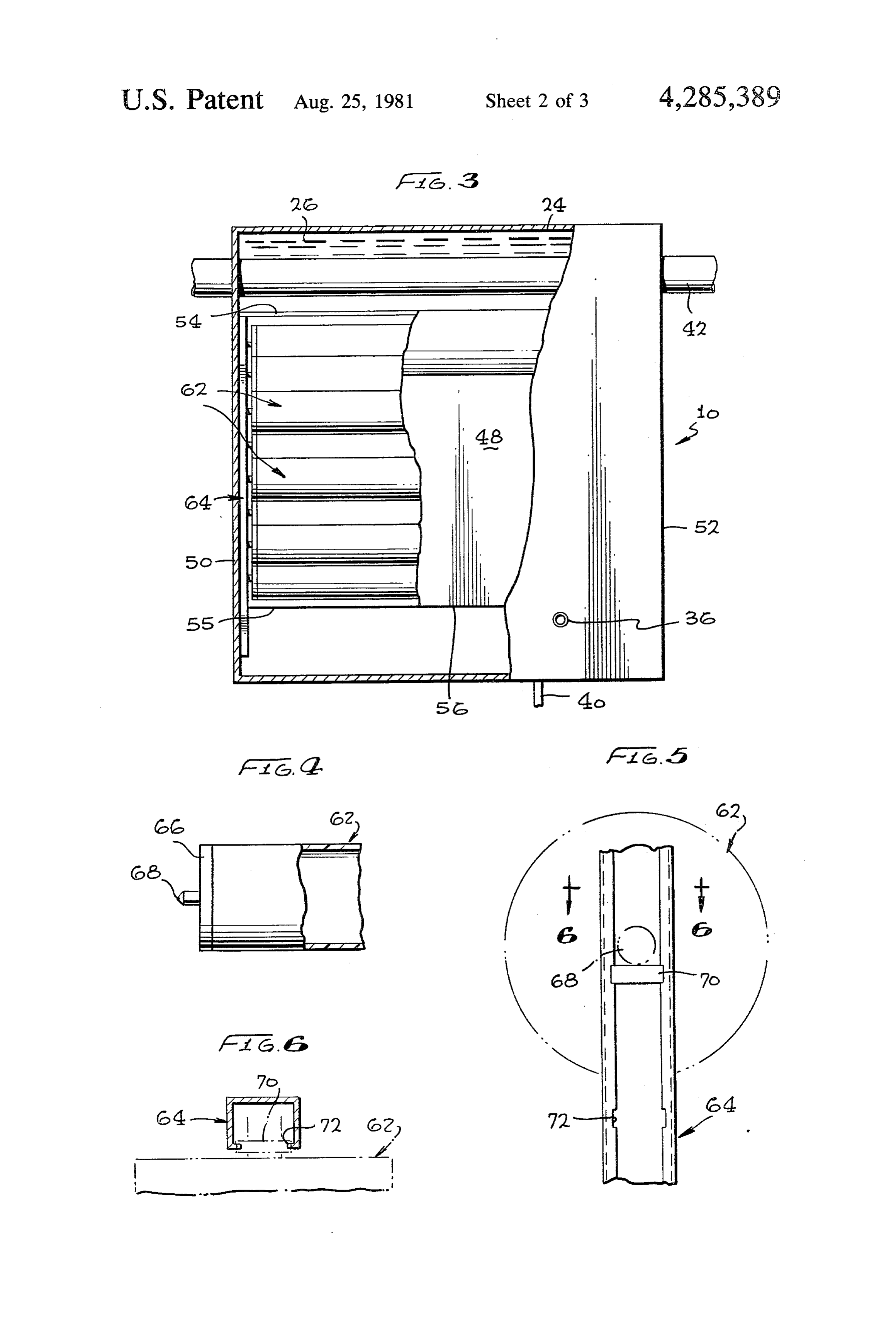
FIG. 2 is an partially cut-away view of the apparatus showing the heat storage ma age material. These materials efficiently absorb and terial containers and baffles; release thermal energy when first used. However, after continued cycling, exothermic characteristics of a salt 45 theFIG. 3 is a side elevation, partially cut-away view of thermal energy storage apparatus taken along line hydrate change due to stratification, and recrystalliza tion is retarded. A slow rate of recrystallization through 3-3 of FIG. 2;
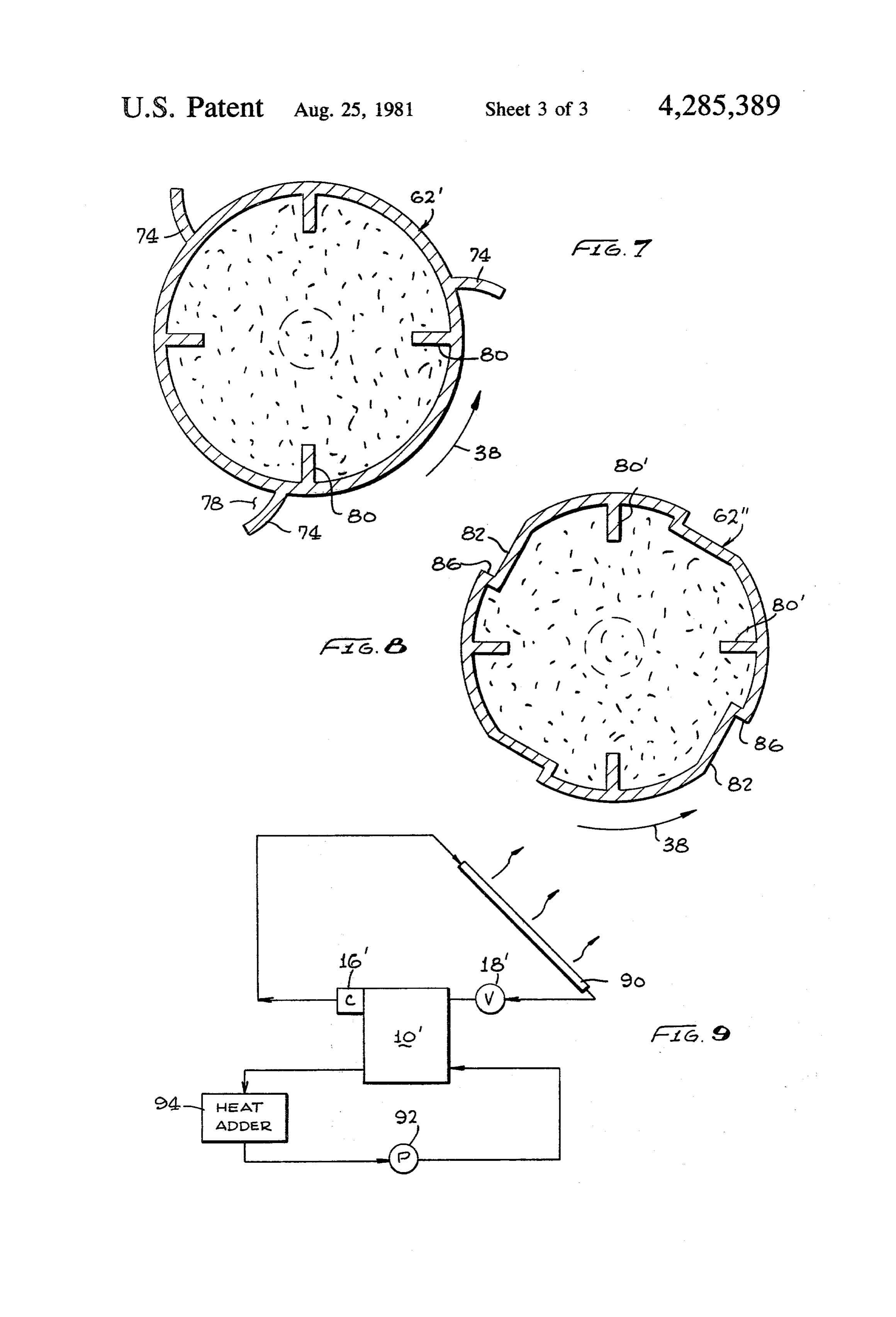
FIG. 4 is a side elevation view of one end of the heat a large hydrate mass limits the rate of heat absorption between the layer closest to the heat source and inner storage material container; and layers. Laboratory tests have indicated that continued 50 used FIG. 5 is a front elevation view of a track and plug mixing combined with an addition of nucleating agents to position a heat storage material container; to promote recrystallization, solves some of these prob FIG. 6 is a cross-sectional view taken along line 6-6 lems. Increasing the added to a heat transfer means in a of FIG. 5;
lower portion of the bath liquid creates a convection FIG. 7 is a cross-sectional view showing a first em current which is cooled as it flows past the heat storage 55 bodiment of the heat storage material container; material containers. At an upper level of the bath liquid, FIG. 8 is a cross-sectional view of a further embodi a baffle means is provided to direct the convection ment of the heat storage material container; and current into a downwardly moving portion so that FIG. 9 is a flow diagram showing the thermal energy movement of the convection current causes the rotat storage apparatus provided by the invention used in ably mounted containers to continually rotate. The 60 conjunction with a thermal energy radiator. containers have inwardly extending protrusions which DETAILED DESCRIPTION continually agitate the heat storage material contained Detailed illustrative embodiments of the invention therein as the containers rotate, thereby preventing
Stratification and increasing efficiency of the heat trans disclosed herein exemplify the invention and are cur fer process as previously explained. 65 rently considered to be the best embodiment for such In specific embodiments of the invention, the con purposes. However, it is to be recognized that other tainer is positioned in an upwardly moving portion of means for rotatably mounting the heat storage material the convection current and is in the form of a longitudi containers and for rotating the containers by use of
Page 6
convection currents could be utilized. Accordingly, the panels, one for each side and one for the top and bottom specific embodiments disclosed are only representative of the container 24. These panels could be formed of in providing a basis for the claims which define the aluminum having a core material of phenolic impreg scope of the present invention. nated kraft paper (honeycomb). Such a material would As previously explained, the invention provides a serve a dual purpose, that is, provide the flexural thermal energy storage apparatus which contains one or strength to support the bath liquid 26 and also provide more rotatably mounted containers holding a heat stor sufficient insulation to minimize heat losses. A six-sided age material such as a salt hydrate having high heat angle-iron, open-box frame could be fitted "aquarium capacity at the transition point between hydrated and style' with five of the sandwich panels, the weight of unhydrated crystal states. A convection current created 10 the bath liquid being used to seal the edges of the panels by heat applied to a lower portion of a bath liquid in against a gasket or high-density mastic compound along which the rotatably mounted containers are submerged the flat sides of the angle iron. The sixth sandwich panel is used to rotate the containers without using other could be bolted to the top of the container utilizing a externally supplied energy. As previously explained, conventional gasket. However, many other types of agitation or mixing of a salt hydrate heat storage mate 15 insulating enclosures could also be utilized. rial is essential in order to maintain exothermic charac A heat transfer duct 36 formed of a heat-conductive teristics of the material. A baffling means is provided in material such as copper is provided in the lower portion the bath liquid so that upwardly moving portions of the of the bath liquid 26. Compressed hot coolant from the convection current can be isolated from downwardly compressor 16 flowing through the heat transfer duct moving portions. In one application, the salt hydrate is 36 is cooled by the bath liquid 26, thereby heating the chosen to have a transition point between hydrated and bath liquid 26 and initiating an upwardly flowing con unhydrated crystals of a relatively high temperature vection current as shown by the arrows at 38. Although such as 95 F., thereby allowing heat from a solar en in this embodiment, a heat transfer duct 36 is shown as ergy collector to be added at the bottom of the bath a straight pipe extending through the bottom of the bath liquid. When needed, heat is removed at the top of the 25 liquid 26, other configurations could be used such as a bath liquid for such purposes as space or hot water coiled duct or a zig-zagged duct. The purpose of the heating. In another application, the salt hydrate is heat transfer duct 36 is to transfer as much as possible of chosen to have a transition point at a relatively low the heat energy contained in the compressed coolant to temperature such as 57 F., thereby allowing heat to be the bath liquid 26. In the event that insufficient heat is removed from the top of the storage apparatus at night, 30 supplied by the solar energy collector 14, heat energy and to be added at the bottom of the storage apparatus from an auxiliary electrical heating element 40 can be during the day by a medium to be cooled, such as air provided. A heat removal duct 42 formed of a highly being used for air conditioning purposes. conductive material is provided at the top of the bath Referring now to FIG. 1, a thermal energy storage liquid 26. This duct could carry any fluid to be heated apparatus 10 is shown in conjunction with a heat extrac 35 such as air or water. Two longitudinally-extending tor 12 which could be a hot water tank or a room to be baffles comprising a first baffle 46 and a second baffle 48 heated by both latent and sensible thermal energy are provided. These baffles 46 and 48 extend the entire stored within the thermal energy storage apparatus 10. length of the enclosure 24, as shown in FIG. 3, and are Also shown are a solar energy collector 14, a compres attached along their side edges to a front side 50 and sor 16 and a refrigerant valve 18, the combination acting back side 52 of the enclosure 24. The upper portions of as a heat pump in which the solar energy collector 14 is the baffles are formed so that they extend inwardly the evaporating side and the heat storage apparatus is towards the center of the enclosure so that their upper the condensing side of the cycle. A suitable coolant edges create a longitudinally-extending gap or convec such as freon is used as a heat transport medium. The tion current exit aperture as shown at 54. The gap 54 is compressor 16 liquifies freon vaporized by the solar 45 positioned directly below the heat removal duct 42. It is energy collector 14 and pumps both sensible and latent preferable that the baffles be formed of a material hav heat into the thermal energy storage apparatus 10. The ing low thermal conductivity so that the bath liquid 26 cooled freon is then returned through the refrigerant separated thereby will be thermally isolated. The lower valve 18 to the solar energy collector 14 to repeat the edges 55 and 56 of the baffles 46 and 48, respectively, cycle. The thermal energy storage apparatus 10 of the 50 are spaced apart from the bottom of the enclosure 24 so present invention is not limited, however, to use in that the bath liquid 26 can pass from side columns 57 conjunction with a solar energy collector, and can be and 58 into a central column 60, the three columns 57, used to store thermal energy provided by a variety of 58 and 60 being defined by the first and second baffles sources such as electrical energy from a solar panel 46 and 48. A plurality of longitudinally-extending tubes array or steam energy from an underground heat 55 or containers 62 for holding a heat storage material are source. Heat is removed from the thermal energy stor rotatably mounted to the front and back sides 50 and 52 age apparatus 10 by flowing a medium to be heated, of the enclosure tank 24. The outer surfaces of the tubes such as air or water, through an upper portion of the 62 are formed so that a convection current in the central thermal energy storage apparatus 10. The medium is column 60 will cause them to rotate. The tubes 62 are circulated by a pump 20. 60 rotatably mounted along vertically extending mounting Referring now to FIGS. 2 and 3, the structure of the tracks 64 as will be explained below. They can be energy storage apparatus 10 provided by the invention mounted in a variety of configurations with respect to can be seen. A container or enclosure 24 for a bath the central column 60. In the configuration shown, the liquid 26 is provided. As one can appreciate, it is impor tubes 62 fill approximately 75% of the volume of the tant that the bath liquid 26 be insulated from the ambi 65 central column 60. By matching the density of the bath ent environment as much as possible consistent with liquid 26 to the density of the storage tubes 62 and the weight and cost constraints. A possible construction for heat storage material contained therein, a "floating log' the bath liquid container 24 could utilize six sandwich condition can be provided. This condition allows the
Page 7
tubes 62 to rotate with a small amount of convection dium sulfate (Na2SO4.10H2O) having a transition tem current flow because they are essentially in a weightless perature of approximately 95 F., each tube and its state. Although the tubes 62 are shown mounted in the associated heat storage material having a specific grav central column 60, they could also be mounted in side ity of approximately 1.2, or slightly less than that of the columns 57 and 58. bath liquid 26. As heat is added to the bath liquid 26 Referring to FIG. 4, each storage tube 62 is con directly below the central column 60, as shown in FIG. structed of a thin wall of extruded plastic material. This 2, an upwardly moving convection current 38 created thin wall can define different types of outer surface by the thus heated bath liquid 26 causes the tubes 62 to configurations, as will be explained below, in order to continually rotate, thereby agitating and mixing the effect rotation by the upwardly moving convection 10 heat storage material contained within the tubes 62. The current. Each tube 62 is fitted at each end with an end heat storage material absorbs heat from the upwardly cap 66 having a pointed extrusion 68 extending from its rising convection current 38 in the form of sensible heat center. One of the vertically-extending mounting tracks and latent heat. When the upwardly moving convection 64 is shown in FIG. 5, a cross-section of which is shown current 38 passes through the convection current exit in FIG. 6. Vertical positioning slugs 70 are anchored by 15 aperture 54, it is isolated by the first and second baffles short, vertically-extending positioning slits 72 posi 46 and 48, respectively from the bath liquid portion tioned along the mounting tracks 64, each slug 70 pro surrounding the tubes 62. The convection current then viding a base upon which one of the pointed extrusions flows downwardly to the bottom of the enclosure 24 as 68 can rest. shown by the arrows at 88. The thus-cooled bath liquid As previously explained, different outer surface con is then reheated and begins to rise again, thereby repeat figurations for the storage tubes 62 can be provided. In ing the cycle. As long as the temperature of the bath one configuration of the storage tube 62", as can be seen liquid within the convection current exit aperture 54 is by referring to FIG. 7, three longitudinally extending cooler than the bath liquid surrounding the tubes 62, turning fins 74 are positioned at 120 degree increments convection currents as shown by 38 and 88 will con around the surface of the tube 62'. These fins 74 extend 25 tinue to flow. Heat is extracted from the thermal energy the length of the storage tube 62, thereby increasing the storage apparatus 10 by flowing a fluid to be heated, surface area exposed to the convection current 38 and such as air or water, through the heat removal duct 42. resisting buckling stresses caused when handling the As the fluid to be heated passes through the heat re storage tubes 62' outside the container. The turning fins moval duct 42, it absorbs heat from the surrounding 74 are angled inwardly towards the surface of the tube 30 bath liquid 26, thereby creating a convection current 62' so that the convection current will impart a different which flows upwardly around the tubes 62. Again, as turning moment on each side of the tube 62'. In the heat is removed from the heat storage material, the configuration shown, the convection current catches an tubes 62 are rotated by the convection current, thereby inside volume 78 formed by the turning fin 74, thereby continually agitating and mixing the heat storage mate causing the storage tube 62 to rotate in a counter-clock 35 rial contained therein. Thus, both sensible heat and wise direction. Inwardly protruding mixing fins 80 are latent heat storage within the bath liquid 26 and heat provided to continually agitate and mix the salt hydrate storage material are removed from the thermal energy heat storage material contained within the storage tube storage apparatus. Another heat storage material which 62", thereby increasing the rate of heat transfer and could be utilized is sodium acetate (NaC2H3O2.3H2O) preventing stratification as previously explained. having a transition temperature of approximately 135 In a second embodiment of the storage tube 62" F.
shown in FIG. 8, a plurality of longitudinally extending In another application, the thermal energy storage notches or grooves 82 are provided in the outside sur apparatus provided by the invention can be utilized in face of the storage tube 62". The upwardly flowing conjunction with an air conditioning system. Here, a convection current 38 impinges against a radially 45 salt hydrate whose transition, point is approximately 57 formed face 86, thereby creating a rotation moment F. is utilized as the heat storage material, thereby stor which causes the storage tube 62' to rotate in a counter ing "cold' at night for use during the day. An example clockwise direction. As with the first storage tube 62", of a salt hydrate having a 57 F. transition point is so four inwardly protruding mixing fins 80' are provided dium hydroxide (NaOH.3H2O). Referring to FIG. 9, to continually agitate and mix the salt hydrate contained 50 an air conditioning system comprising a thermal energy therein as the storage tube 62" rotates. As one can ap storage apparatus 10' provided by the invention, a com preciate, the above examples are only illustrative of the pressor 16', a refrigerant valve 18", and a thermal energy general type of storage tube 62 provided by the inven radiator 90 are shown. Here the compressor 16 com tion. Other configurations could be utilized. For exam presses a coolant fluid which is provided to the thermal ple, the storage tubes could be rotatably mounted so 55 energy radiator 90 which in turn cools the coolant fluid that the pointed extrusions 68 extend through the first through radiation of latent and sensible heat contained and second baffles 46 and 48. Turning fins could then be therein. The thus-cooled coolant fluid passes through attached to portions of the protrusions extending the refrigerant valve 18' into the thermal energy storage through the baffles, thereby providing a means whereby apparatus 10", thereby cooling the top portion of the the tubes 62 could be rotated by the downwardly flow 60 bath liquid 26. This cooled bath liquid above the con ing portion of the convection current. vection current exit aperture 54 causes a convection In a specific application where thermal energy stored current to flow, the flow being maintained so long as within the thermal energy storage apparatus 10 is to be the top portion of the bath liquid 26 remains cooler than used for heating purposes, the bath liquid 26 can com the bottom portion. As in the previous application, the prise anhydrous CaCl2 which is mixed with an appropri 65 convection current causes the tubes 62 to continually ate amount of water to provide a specific gravity of 1.3. rotate, thereby agitating and mixing the salt hydrate The tubes 62 are formed of a fairly light plastic material, heat storage material contained therein. During the day, and filled with a heat storage material comprising so "cold' is removed from the thermal energy storage
Page 8
apparatus 10' by pumping a fluid through the heat trans closure bottom, said second baffle having an upper fer duct 36 in the bottom portion of the bath enclosure section extending inwardly towards the one side of 24 by use of a pump 92. As heat is removed from the said first side pair, the upper edges of said first and fluid being pumped, heat is added to the bath liquid 26 second baffle upper sections defining an exit aper surrounding the heat transfer duct 36, thereby creating ture for said upwardly flowing convection current, a upwardly moving convection current in the central the vertically extending column between said first column 60. As the bath liquid 26 flows around the tube and second baffles comprising said column contain 62, it is cooled. A heat adder 94 is shown which could ing said plurality of rotatably mounted cylinders. be either a room to be air conditioned or water to be 6. The energy storage apparatus of claim 5 wherein cooled. 10 said means for removing heat is positioned above said It should now be apparent that a thermal energy exit aperture.
storage apparatus has been described in which tubes 7. The energy storage apparatus of claim 3 wherein containing a heat storage material, such as a salt hy said means for rotating comprises elongated protrusions drate, are rotated by convection currents in a bath liq formed along the outer surface of said cylinders uid created as a result of a heat transfer process. The 15 whereby the force of said flowing convection current heat storage material can be chosen to have a relatively against said elongated protrusions causes said cylinders high or low transition point depending on whether the to rotate.
thermal energy storage devise is to be used as part of a heating or cooling system. The life of a salt hydrate heat said8. The energy storage apparatus of claim 7 wherein cylinders are located in said convection current storage material is extended as a result of continual 20 upwardly flowing portion. agitation and mixing during the heat transfer process, this agitation and mixing being accomplished entirely said means for rotating apparatus 9. The energy storage comprises of claim 3 wherein elongated notches by convection currents formed within the bath liquid. formed along the surface of said cylinders. What is claimed is:
1. A thermal energy storage apparatus comprising: 25 wherein 10. The thermal energy storage apparatus of claim 1 a bath liquid; the weight of said bath liquid displaced by said one or more containers holding a heat storage mate weight of said containers one or more is substantially equal to the rial, said containers being submerged in said bath ated heat storage material. containers and their associ one or more liquid means for transferring heat to a lower portion of said 30 said11.bathThe energy storage apparatus of claim 1 wherein liquid comprises approximately 70 percent bath liquid thereby creating a convection current having upwardly flowing and downwardly flow water and 30 percent anhydrous CaCl2. ing portions; 12. The energy storage apparatus of claim 1 wherein means for rotatably mounting said one or more con said heat storage material comprises sodium sulfate tainers so that said containers are located in said 35 (Na2SO4.10H2O).
convection current flowing portion; 13. A thermal storage apparatus comprising: means for isolating said convection current upwardly an enclosure holding a bath liquid; flowing portion from said convection current a heat source in heat transfer relationship to a lower downward flowing portion; and portion of said bath liquid;
means for rotating said at least one heat storage con 40 rotatably mounted containers holding a heat storage tainer by said convection current. material, said containers being located in an up 2. The energy storage apparatus of claim 1 further wardly moving portion of a convection current comprising means for removing heat from said thermal created by said heat source in said bath liquid; storage apparatus. baffle means isolating said upwardly moving portion 3. The energy storage apparatus of claim 2 wherein 45 of said convection current from a downwardly said one or more containers comprise a plurality of moving portion of said convection current; and containers, each of which comprises an elongated cylin means for rotating said containers by movement of der, the inner surface of which forms a plurality of said convection current. protrusions for agitating said heat storage material con 14. The apparatus of claim 13 further comprising a tained therein as said cylinders rotate. 50 heat removal means in heat transfer relationship to an 4. The energy storage apparatus of claim 3 wherein upper portion of said bath liquid.
said means for isolating comprises a baffle means defin 15. The apparatus of claim 14 wherein said heat re ing vertically extending columns within said bath liquid, moval means comprises ducting through which a me at least one of said columns containing said plurality of dium to be heated is flowing.
rotatably mounted elongated cylinders. 55 16. The apparatus of claim 14 wherein said bath liquid 5. The energy storage apparatus of claim 4 wherein comprises approximately 70 percent water and 30 per said bath liquid is contained in an enclosure having first cent anhydrous calcium chloride (CaCl2) and said heat and second side pairs and a top and bottom, said baffle storage material comprises sodium sulfate (Na2SO4.10 means comprising: H2O).
a first vertically-extending baffle spaced between the 60 17. The apparatus of claim 14 wherein said bath liquid center and one side of said first side pair so that its comprises approximately 70 percent water and 30 per bottom edge is spaced apart from said enclosure cent anhydrous calcium chloride (CaCl2) and said heat bottom, said first baffle having an upper section storage material comprises sodium acetate (NaC2 extending inwardly towards the other side of said H3O2.3H2O).
first side pair; and 65 18. The apparatus of claim 14 wherein said heat a second vertically-extending baffle spaced between source comprises ducting through which a medium to the center and the other side of said first side pair so be cooled is flowing, and said heat removal means com that its bottom edge is spaced apart from said en prises ducting through which a medium to be heated is
Page 9
flowing, said medium to be heated being colder than rotatably mounting heat storage one or material in more containers a portion of saidholding conveca said medium to be cooled. tion current;
19, The apparatus of claim 18 wherein said bath liquid. rotating said containers by said convection current; comprises approximately 70 percent water and 30 per- 5 and cent anhydrous CaCl2 and said heat storage material isolating said rotatably mounted containers from a comprises sodium hydroxide (NaOH.3H2O). downwardly moving portion of said convection
h A thod of storing thermal energy comprising 21.current.
The method of claim 20 further comprising the the steps of: 10 step of removing heat from an upper portion of said heating a lower portion of a bath liquid thereby creat- bath liquid.
ing a convection current in said bath liquid; sk & it sk
Provenance
- Collection
- Cited prior art
- Original PDF
- patentimages.storage.googleapis.com →
- Filed
- 1979-12-26
- Pages
- 9
- Method
- pdftotext (the PDF's own text layer) + pdftoppm 300dpi page scans
- Source
- Google Patents bibliographic record
- Granted
- 1981-08-25
- Inventors
- Jack F. Horton
- Transcribed from
- patentimages.storage.googleapis.com →