patent · US4188941
Solar heating system
19 February 1980
Page 1 — bibliographic record
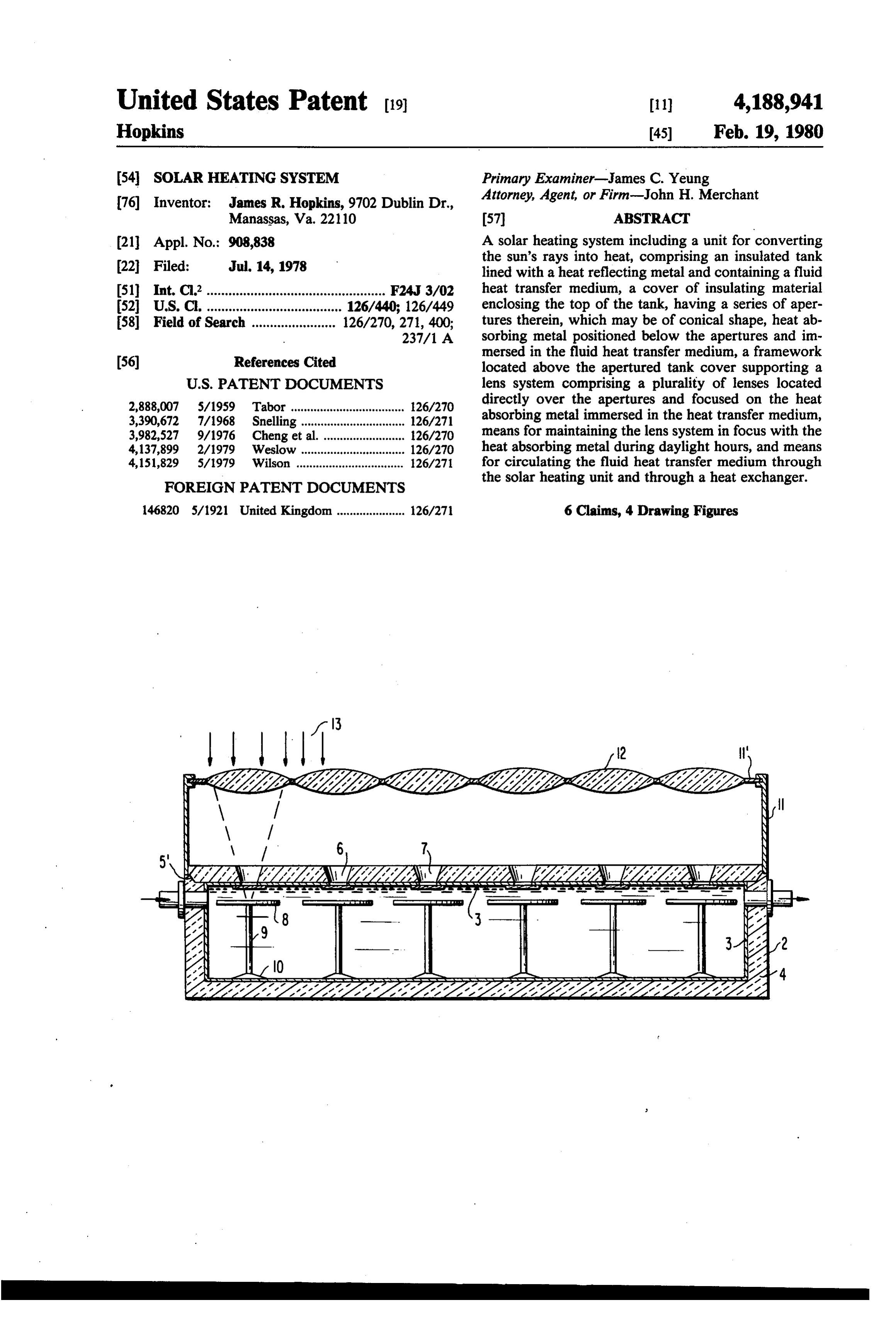
United States Patent (19) 11) 4,188,941 Hopkins 45) Feb. 19, 1980 (54) SOLAR HEATING SYSTEM Primary Examiner-James C. Yeung 76 Inventor: James R. Hopkins, 9702 Dublin Dr., Attorney, Agent, or Firm-John H. Merchant Manassas, Va. 22110 57 ABSTRACT (21) Appl. No.: 908,838 A solar heating system including a unit for converting
the sun's rays into heat, comprising an insulated tank lined with a heat reflecting metal and containing a fluid 5ll Int. Cl’................................................. F24J 3/02 heat transfer medium, a cover of insulating material 52 U.S. C. ..................................... 126/440; 126/449 enclosing the top of the tank, having a series of aper 58 Field of Search ....................... 126/270,271, 400; tures therein, which may be of conical shape, heat ab 237/1 A sorbing metal positioned below the apertures and im
mersed in the fluid heat transfer medium, a framework located above the apertured tank cover supporting a
2,888,007 5/1959 Tabor ................................... 126/270 directly over the apertures and focused on the heat 3,390,672 7/1968 Snelling. 126/271 absorbing metal immersed in the heat transfer medium, 3,982,527 9/1976 Cheng et a ... 26/270 means for maintaining the lens system in focus with the 4,137,899 2/1979 Weslow ... ... 126/270 heat absorbing metal during daylight hours, and means 4,151,829 5/1979 Wilson ................................. 126/271 for circulating the fluid heat transfer medium through
FOREIGN PATENT DOCUMENTS
the solar heating unit and through a heat exchanger.
146820 5/1921 United Kingdom..................... 126/27 6 Claims, 4 Drawing Figures
Jill
Page 2
Drawing sheet — no readable text.
Page 3
material enclosing the top of the tank, a plurality of
SOLAR HEATING SYSTEM apertures, preferably of conical shape, in the cover, heat absorbing metal positioned directly below each aper
BACKGROUND OF THE INVENTION ture and immersed in the heat transfer medium, and The use of solar energy to supplement and replace, in 5 means for supporting the heat absorbing metal above part, reliance on conventional energy sources such as the bottom of the tank. A framework is mounted above oil, coal, and other fossil fuels, has become a matter of the apertured cover for supporting a plurality of magni national concern and the subject of increasing techno fying lenses directly over the apertures in the tank logical research. As our source of fossil fuels is gradu cover, the lenses being focused on the heat absorbing ally depleted and we are forced to rely on increased 10 metal immersed in the fluid heat transfer medium. The imports of foreign oil, resulting in increasing trade defi entire heating unit, including the lens system, is cits, the necessity for developing new sources of energy mounted for oscillating or partial rotative movement to becomes apparent. While nuclear reactors may be a track with the sun and maintain the lens system in focus partial solution to our problem, at the present state of with the rays of the sun during daylight hours. development, this source of energy has proved ex 15 tremely costly and the disposal of waste products poses a problem.
DESCRIPTION OF THE DRAWINGS
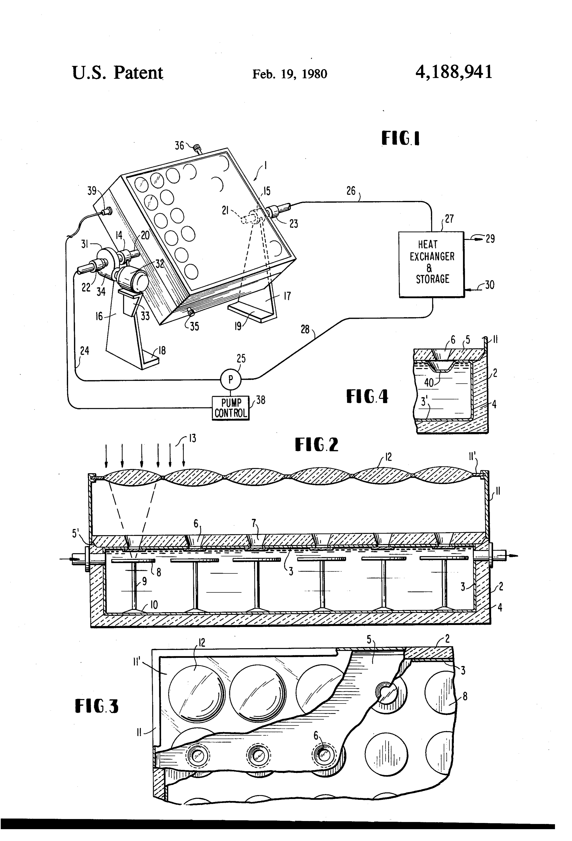
FIG. 1 is a perspective view of the solar heating unit
Development of efficient solar heating devices and mounted for partial rotation, with the associated de systems, particularly in those sections of the country vices, namely, the heat exchanger, circulating pump and blessed with an abundance of sunshine, seems to be a 20 controls, and the piping system, being diagrammatically logical approach in an effort to alleviate our energy shown.
crisis. Solar energy offers many advantages in that the FIG. 2 is a longitudinal section taken along the center supply seems endless and it provides a clean source of of the solar heating unit.
heat without resulting in any objectional end products. FIG. 3 is a fragmentary top view of the solar heating Various types of solar heating systems have been 25 unit, with parts broken away.
proposed, including for example, heating units which constitute a structural part of the roof of a building, as the solar4 isheating
FIG. a sectional view taken along the center of unit at one end thereof showing a shown in the U.S. Patent to Moore, No. 4,010,733, and modification in which the metal lining of the tank serves the U.S. Patent to Warren, No. 4,029,080. Units of this as the heat absorbing metal and is provided with inden type, being an integral part of the building, are necessar 30 ily restricted to use in a single location and cannot be tations located directly below the apertures in the insu lating cover.
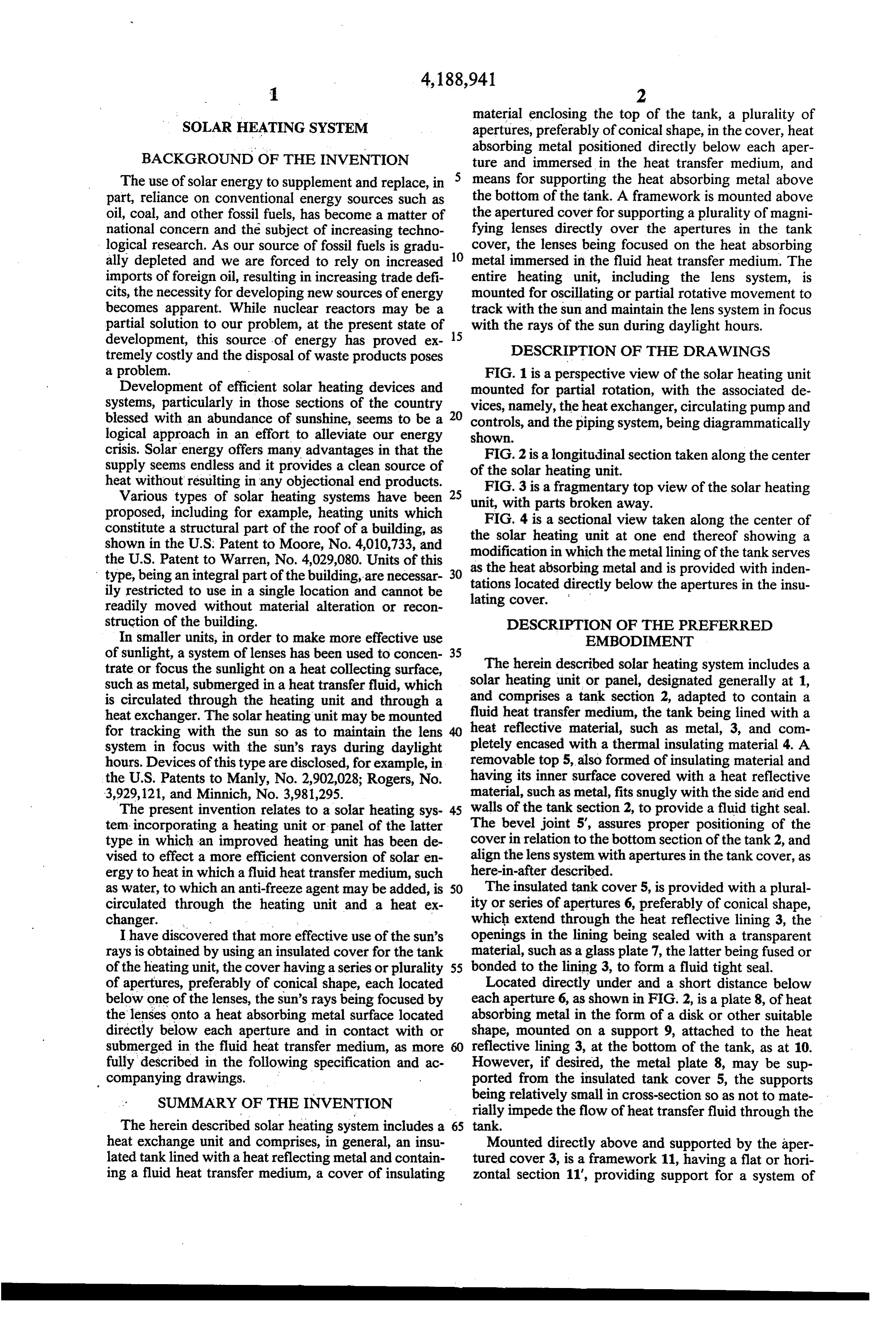
readily moved without material alteration or recon struction of the building. DESCRIPTION OF THE PREFERRED In smaller units, in order to make more effective use EMBODIMENT of sunlight, a system of lenses has been used to concen 35 The herein described solar heating system includes a trate or focus the sunlight on a heat collecting surface, solar heating unit or panel, designated generally at 1, such as metal, submerged in a heat transfer fluid, which is circulated through the heating unit and through a and comprises a tank section 2, adapted to contain a heat exchanger. The solar heating unit may be mounted fluid heat transfer medium, the tank being lined with a for tracking with the sun so as to maintain the lens heat reflective material, such as metal, 3, and com system in focus with the sun's rays during daylight pletely encased with a thermal insulating material 4. A hours. Devices of this type are disclosed, for example, in removable top 5, also formed of insulating material and the U.S. Patents to Manly, No. 2,902,028; Rogers, No. having its inner surface covered with a heat reflective 3,929, 121, and Minnich, No. 3,981,295. material, such as metal, fits snugly with the side and end The present invention relates to a solar heating sys 45 walls of the tank section 2, to provide a fluid tight seal. tem incorporating a heating unit or panel of the latter The bevel joint 5', assures proper positioning of the type in which an improved heating unit has been de cover in relation to the bottom section of the tank 2, and vised to effect a more efficient conversion of solar en align the lens system with apertures in the tank cover, as ergy to heat in which a fluid heat transfer medium, such here-in-after described.
as water, to which an anti-freeze agent may be added, is 50 The insulated tank cover 5, is provided with a plural circulated through the heating unit and a heat ex ity or series of apertures 6, preferably of conical shape, changer. . . which extend through the heat reflective lining 3, the I have discovered that more effective use of the sun's openings in the lining being sealed with a transparent rays is obtained by using an insulated cover for the tank material, such as a glass plate 7, the latter being fused or of the heating unit, the cover having a series or plurality 55 bonded to the lining 3, to form a fluid tight seal. of apertures, preferably of conical shape, each located Located directly under and a short distance below below one of the lenses, the sun's rays being focused by each aperture 6, as shown in FIG. 2, is a plate 8, of heat the lenses onto a heat absorbing metal surface located absorbing metal in the form of a disk or other suitable directly below each aperture and in contact with or shape, mounted on a support 9, attached to the heat submerged in the fluid heat transfer medium, as more reflective lining 3, at the bottom of the tank, as at 10. fully described in the following specification and ac However, if desired, the metal plate 8, may be sup companying drawings. ported from the insulated tank cover 5, the supports SUMMARY OF THE INVENTION being relatively small in cross-section so as not to mate rially impede the flow of heat transfer fluid through the
The herein described solar heating system includes a 65 tank.
heat exchange unit and comprises, in general, an insu Mounted directly above and supported by the aper lated tanklined with a heat reflecting metal and contain tured cover 3, is a framework 11, having a flat or hori ing a fluid heat transfer medium, a cover of insulating zontal section 11", providing support for a system of
Page 4
lenses 12, each lens being located directly above an ration effects a rapid transfer of heat to the fluid heat aperture 6, in the insulated cover 5, and at a distance at exchange medium. In this modification of metal lining which the sun's rays, designated generally at 13, will be 3', covers the apertures in the insulating cover 5, and no focused through the apertures 6, and directly onto the additional seal is needed.
metal plates or disks 8. My invention has been described with reference to As shown in FIG. 1, the solar heating unit or panel is the preferred embodiment thereof, but it will be under mounted on bearings 14, and 15, so that it can be partly stood that other variations and changes, obvious to rotated or oscillated to track with the sun. The latter those skilled in the art made be made within the spirit of bearings are supported by frame members 16, and 17, the appended claims. For example, the number of and each frame member having a flange 18, and 19, respec O arrangement of lenses employed may be varied depend tively, to provide for a more stable or permanent ing upon the amount of energy desired to be transferred mounting, if desired. to the heat exchanger.
An inlet pipe 20, and an outlet pipe 21, which as What is claimed is:
previously noted, provide partly rotative support for 1. A solar heating system for converting the rays of the solar heating unit, said pipes being substantially at 15 the sun into heat, comprising, the same or slightly lower lever than the heat absorbing a sealed solar heating unit having a tank lined with a metal disks 8. These pipes are attached to the lower heat reflective metal and containing a fluid heat section 2, of the tank, and are mounted in bearings 14, transfer medium completely filling the tank, insu and 15, to support the solar heating unit or panel so that lating material encasing the tank, the latter may be partly rotated. 20 a removable cover of insulating material having a
A fluid-tight rotative coupling 22, connects the inlet heat reflective metal lining, said cover enclosing pipe 24, leading to a circulating pump 25, while a like the top of said tank, m coupling 23, connects the outlet pipe 21, with the heat a series of conical shaped apertures in said cover exchanger 27, through pipe 26. Pipe 28, connects the extending through the insulated cover and the pump 25, with the heat exchanger to provide circula 25 metal lining thereof, the bottoms of the apertures tion of the heat exchange fluid from the heat exchanger being closed with transparent plates sealed to the 27, through the pump 25, the solar heating unit, and inner surface of the heat reflective metal lining of back to the heat exchanger 27. The heat exchanger, the cover, flat heat absorbing metal units posi which is encased in insulation to minimize heat loss, is tioned directly below said apertures and immersed provided with an outlet 29, and an inlet 30, for circulat 30 in the fluid heat transfer medium, ing a heat transfer fluid to the desired point of use. means for supporting the flat heat absorbing metal A tracking unit, designated generally by the numeral 31, includes a motor 32, mounted on a bracket 33, at units below the apertures in said cover, tached to the frame member 16, reducing and reversing a framework located above the apertured cover of gearing to oscillate the solar heating unit, serves to 35 a series said tank, and maintain the lens system in focus with the sun's rays and of magnifying lenses located directly over the the unit operating at maximum efficiency during day apertures in the tank cover focused on the upper light hours. Appropriate and conventional electrical surface of the flat heat absorbing metal units in controls, not shown, may be used for this purpose. mersed in the fluid heat transfer medium. In place of the inlet pipe 20, and the outlet pipe 21, of 40 2. A solar heat unit as defined in claim 1, in which the the solar heating unit, these openings may be capped heat absorbing metal is in the form of disks supported and alternate inlet 35, and alternate outlet 36, may be above the bottom of the tank, the tank having an inlet connected by means of flexible pipes, not shown, to and an outlet connected with a heat exchanger, and provide circulation of the heat transfer fluid through means for circulating the fluid heat exchange medium the solar heating unit and the heat exchanger. If this 45 through the tank and the heat exchanger. modification is used, solid rods may be substituted for 3. A solar heat unit as defined in claim 1, in which the the pipes 20, and 21, shown in the drawings, to support tank is pivotally mounted for oscillating movement, the solar heating unit. means for oscillating the tank and the lens system to A heat sensing device 39, is electrically connected by maintain the lenses focused on the heat absorbing metal. cable 37, with motor control means 38, to actuate a 50 during periods of operation.
motor for the pump 25, when the heat transfer fluid 4. A solar heat unit as defined in claim 1, in which the reaches the desired temperature and to cut off the motor tank is provided with inlet and outlet pipes positioned at actuating the pump when the temperature falls below a the approximate level of the flat heat absorbing metal specified level. units, for circulation of the fluid heat transfer medium The heat sensing device 39, may be located at other 55 therethrough, said pipes pivotally supporting the unit points in the solar heating unit than illustrated in the for oscillating movement, a circulating pump, and a drawing, and it may, for example, be mounted adjacent heat exchanger, the inlet and outlet pipes being con to or under the lower surface of one of the metal plates nected to the circulating pump and the heat exchanger or disks 8, or adjacent an inlet pipe 20, or 35. through fluid-tight couplings.
In the modification illustrated in FIG. 4, a metal 5. A solar heating unit as defined in claim 1, the metal lining 3", for the apertured cover 5, of the tank section 2, lining for the cover having indentations below and serves as the heat absorbing metal and is provided aligned with each aperture in the cover.
below each aperture with an indentation 40, the lower 6. A solar heating unit as defined in claim 1, in which surface of which is in direct contact with the fluid heat the heat exchange medium is a liquid. exchange medium contained in the tank 2. This configu 65
Provenance
- Collection
- Cited prior art
- Original PDF
- patentimages.storage.googleapis.com →
- Filed
- 1978-07-14
- Pages
- 4
- Method
- pdftotext (the PDF's own text layer) + pdftoppm 300dpi page scans
- Source
- Google Patents bibliographic record
- Granted
- 1980-02-19
- Inventors
- James R. Hopkins
- Transcribed from
- patentimages.storage.googleapis.com →