patent · US20090121495A1
Combined cycle power plant
14 May 2009
Page 1 — bibliographic record
(19) United States (12) Patent Application Publication (10) Pub. No.: US 2009/0121495 A1
Mills (43) Pub. Date: May 14, 2009 (54) COMBINED CYCLE POWER PLANT FOIK 3/08 (2006.01)
(76) Inventor: David R. Mills, Palo Alto, CA (US) F03G 6/06 (2006.01) Correspondence Address:
MORRISON & FOERSTER LLP (52) U.S. Cl. ............... 290/4 D; 290/52: 60/597; 60/659; 7SS PAGE MILL RD 60/641.15
(21) Appl. No.: 12/157,067 (57) ABSTRACT (22) Filed: Jun. 6, 2008 Combined cycle power plants and related methods are dis closed here. In the plants, a mediating thermal energy storage
Related U.S. Application Data unit is used to store waste or residual thermal energy recov ered from a heat engine employing a top thermodynamic (60) Provisional application No. 60/933,619, filed on Jun. cycle of the combined cycle power plant, so that the stored 6, 2007. residual thermal energy may be used as an energy source in a Publication Classificati bottom thermodynamic cycle of the power plant. In the com ublication Classification bined cycle power plants described here, the heat engine (51) Int. Cl. employing a top cycle may comprise a Brayton cycle heat FOID 5/10 (2006.01) engine and the heat engine employing the bottom thermody HO2K 7/8 (2006.01) namic cycle may be a Rankine cycle heat engine.
Page 2
Drawing sheet — no readable text.
Page 3
Drawing sheet — no readable text.
Page 4
Drawing sheet — no readable text.
Page 5
US 2009/012 1495 A1 May 14, 2009
COMBINED CYCLE POWER PLANT fuel) may be used in addition to the stored thermal energy to drive a bottom cycle heat engine.
CROSS-REFERENCE TO RELATED 0007. The methods may comprise generating electricity
APPLICATIONS
using any suitable combination of top and bottom cycle heat 0001. This application claims benefit of priority from U.S. engines generating electrical energy. For example, in some Provisional Patent Application Ser. No. 60/933,619, entitled variations, the top cycle heat engine may employ a Brayton “Combined Cycle Power Plant.” filed Jun. 6, 2007, which is cycle, and Such top cycle heat engines include a heavy duty hereby incorporated by reference herein in its entirety. This Brayton cycle turbine that may be powered by natural gas or application is also related to U.S. patent application Ser. No. an aeroderivative Brayton cycle turbine that may be powered entitled “Integrated Solar Energy Receiver-Storage by natural gas. Externally heated versions of the Brayton Unit' (Attorney Docket No. 62715-2000400), which claims cycle heat engine are possible and, if heat is recuperated benefit of priority from U.S. Provisional Patent Application between the expansion and compression portions of these Ser. No. 60/933,620, entitled “Integrated Solar Energy heat engines, the externally-heated versions are said to use the Receiver-Storage Unit filed Jun. 6, 2007, each of which is Ericsson cycle. Solar heat is one form of external heat that hereby incorporated by reference herein in its entirety. may be applied to a Brayton-cycle or Ericsson-cycle heat
FIELD
engine. Abottom cycle heat engine may employ a Rankine or
Kalina cycle where the working fluid undergoes a phase 0002 This application relates to a combined cycle power change, Thus, the methods may comprise compressing, heat plant that incorporates a thermal energy storage system. ing and expanding a first working fluid through a first turbine to drive a first electrical generator which employs a top ther
BACKGROUND modynamic cycle, storing residual thermal energy contained 0003 Well known are thermal power plants that combine in the first working fluid following its expansion, heating a Brayton cycle and Rankine cycle systems and in which heat second working fluid with the stored thermal energy, and recovered from exhausted Brayton cycle fluid is employed in generating electrical energy with a second electrical genera a Heat Recovery Steam Generator (“HRSG”) to generate or tor using the heated second working fluid, e.g., in a Rankine augment the generation of steam for expansion in the Rankine cycle heat engine. Any Suitable working fluids may be used in cycle system. These known combined cycle systems combin the top and bottom thermodynamic cycles, e.g., the first work ing two thermodynamic cycles in sequence can provide for ing fluid may comprise primarily air (e.g., ambient air), and greater operating efficiency and/or faster start-up than single the second working fluid may comprise steam, water, a steam/ cycle systems. water mixtures, or a hydrocarbon fluid. 0008 If the plant includes a Rankine cycle heat engine in
SUMMARY its bottom thermodynamic cycle to generate electricity, for 0004 Broadly, methods and combined cycle power plants instance, the methods may comprise heating the second are disclosed here in which a mediating thermal energy Stor working fluid with the stored thermal energy, and expanding age unit is used to store waste or residual thermal energy the heated second working fluid through a second turbine garnered from a portion of the plant which employs a top coupled to a second electrical generator. In some variations of thermodynamic cycle to generate electricity, so that the stored a Rankine cycle heat engine, the heated compressed second residual thermal energy may be used as an energy source in a working fluid may be successively expanded through a series portion of the plant which employs a bottom thermodynamic of multiple expansion stages, e.g. multiple turbines. In these cycle to generate additional electricity. variations, the methods may comprise reheating the second 0005 Thus, methods are disclosed here that comprise (a) working fluid between expansion stages, which reheating in generating electrical energy and residual thermal energy Some variations may be accomplished using stored thermal using a first top-cycle heat engine operating with a top ther energy recovered from the top cycle heat engine. modynamic cycle, (b) storing at least a portion of the residual 0009. The methods may comprise storing residual thermal thermal energy, and (c) using at least a portion of the stored energy recovered from a top cycle heat engine using any residual thermal energy to generate additional electrical Suitable mediating thermal energy storage system. For energy in a first bottom-cycle heat engine operating with a example, thermal energy storage systems utilizing a thermal bottom thermodynamic cycle. Some methods may comprise energy storage medium comprising an aggregate, Sand, con storing all of the recovered residual thermal energy, whereas crete, a molten salt, or phase change material (e.g. paraffin, other methods may comprise storing a portion of the recov fatty acid, or salt hydrate) or a combination thereof may be ered residual thermal energy and diverting a portion of the used.
residual thermal energy for immediate use in generating elec 0010. The methods may comprise storing the residual tricity via the bottom thermodynamic cycle. thermal energy recovered from a top cycle heat engine for any 0006. The methods may comprise using any suitable fuel desired length of time. For example, in some cases, the stored or energy source to drive atop cycle heat engine. For example, thermal energy may be stored on a transient basis, e.g., for a Solar energy may be used, such as Solar energy collected from period of about 15 minutes or less. In other cases, the stored a tower Solar array (e.g., a multi-tower Solar array), a Solar thermal energy may be stored for more extended periods, e.g., array using parabolic troughs, or a linear Fresnel reflector for a period longer than about 15 minutes. Such as a few hours. Solar array. Alternatively or in addition, fuels such as fossil In some cases, a storage period may be determined based on fuels and/or biomass-derived fuels may be used to power atop a 24 hour cycle. The methods may comprise adjusting a cycle heat engine. In certain cases, a Supplemental energy storage time depending on energy demand, e.g., adjusting a Source (e.g., Solar energy, fossil fuel, and/or biomass-derived storage time of the recovered residual energy so that a com
Page 6
US 2009/012 1495 A1 May 14, 2009
bined electrical output of the top and bottom cycle heat bottom cycle working fluid, most frequently water, and a engines meets a fluctuating demand, a baseline demand, and/ second turbine. The second turbine is configured to expand or a peak demand. the second working fluid to drive a second generator. The 0011 A power plant may therefore “time-shift' electrical second working fluid may be solely heated with the stored generation by accumulating residual heat from a top-cycle thermal energy recovered from a top cycle heat engine, or heat engine and using that residual heat in a bottom-cycle heat additionally use a Supplemental energy source Such as Solar engine at a different time of day or at night, for instance. A energy, fossil fuel, biomass-derived fuel, or any combination power plant may also incorporate thermal energy storage in thereof. In some of the latter variations of plants, the second other areas of the power plant. For instance, a thermal energy turbine may comprise multiple expansion turbines for storage unit may accumulate heat that is used to power a sequentially expanding the second working fluid. A reheating top-cycle heat engine and release that heat on demand to stage may or may not be provided to reheat the working fluid continue producing electrical energy from a top-cycle heat between Successive expansions. If used, a reheating stage engine, thus Supplementing or replacing a primary heat may be powered by Stored thermal energy obtained from atop Source (such as natural gas) that is used to power the top cycle cycle heat engine, Solar energy, fossil fuel, biomass-derived heat engine. In one instance, a thermal energy storage unit for fuel, or any combination thereof. a top cycle heat engine stores thermal energy at a temperature 0017. In some plants, there will be a plurality of top cycle between 800 C and 1200 C. heat engines operating in parallel, (e.g., Brayton cycle heat 0012. The methods may be used to produce electricity at engines), and the mediating thermal energy storage unit or high efficiency, e.g., with a combined efficiency from the top units may be configured to accumulate and store thermal and bottom cycle heat engines of about 60% or greater, about energy obtained from each engine in the set. 65% or greater, about 70% or greater. In some cases, the 0018. The mediating thermal energy storage unit of the capacities and/or efficiencies between the top and bottom plants described herein may comprise any suitable configu cycle heat engines may be substantially matched. ration and thermal energy storage medium. For example, a 0013 These methods may employ a variety of schemes to thermal energy storage medium may employ, depending on increase a combined efficiency of the top and bottom cycle the temperature range, a thermal energy storage medium heat engines. For example, there may be a plurality of top comprising an aggregate, rock, Sand, concrete, a molten salt, cycle heat engines operating in parallel and employing the Solid metal oxide, Solid metal nitride, or a combination same thermodynamic cycle (e.g., multiple Brayton cycle tur thereof.
bines), and the methods may comprise accumulating and 0019. Further, characteristics and/or settings of any com storing residual energy from Some or all of the engines in the bination of the first and bottom cycle heat engines and medi set and using the accumulated Stored residual energy to drive ating thermal energy storage unit may be selected so as to a large and efficient single bottom cycle heat engine, which increase an overall collection efficiency of a combined cycle may be a Rankine cycle heat engine. In the methods in which system. In some instances, the top and bottom cycle heat residual energy from multiple top cycle heat engines (e.g., engines may exhibit a combined efficiency of about 60% or multiple Brayton cycle heat engines) is accumulated, a com higher, about 65% or higher, about 70% or higher. bined efficiency of at least about 65% or even higher may be 0020. The plants may be configured for a variety of elec achieved. trical energy Supply roles. For example, the plants may be 0014. As stated above, electrical power plants are also configured as a load following plant, e.g., a Solar powered disclosed here. In general, the electrical power plants com load following plant. Variations of the plants may be config prise one or more top cycle heat engines configured to gen ured to Supply a baseline amount of electrical energy or peak erate electrical energy, one or more bottom cycle heat engines amounts of electrical energy.
configured to generate electrical energy, and one or more 0021 Certain variations of the plants may comprise ther mediating thermal energy storage units configured to store mal energy storage units in addition to the mediating thermal residual thermal energy recovered from the top cycle heat energy storage unit used to store residual thermal energy engines so that the stored residual thermal energy from the top garnered from the top cycle heat engines. Thus, one or more cycle heat engines may be used to operate one or more bottom thermal energy storage units may be employed to store heat in cycle heat engines. A top cycle heat engine may comprise a excess of that needed to power the top cycle heat engines at a Brayton cycle heat engine (e.g., a heavy duty gasturbine oran temperature Suitable for powering one or more top cycle heat aeroderivative gas turbine); a bottom cycle heat engine may engines at a later time. Excess thermal energy obtained from comprise a Rankine cycle engine, for example. a liquid or gaseous stream discharged by a top cycle heat 0015 Thus, in some variations, the top cycle heat engine engine can be retained in the mediating thermal storage unit. may comprise a first compressor configured to compress a 0022. Power plants disclosed herein may comprise addi first working fluid, a first heating stage for heating the com tional features related to the Supply of energy used to heat a pressed working fluid, and a first turbine configured to expand working fluid for use in a top and/or a bottom cycle heat the first working fluid to drive a first generator. Any suitable engine. For example, the plants may comprise a receiver energy source may be used to power the first high temperature configured to absorb reflected solar radiation from one or heating stage in the top cycle heat engine, e.g., Solar energy more reflectors, and the receiver may, in turn, heat a first from a linear Fresnel Solar thermal array, a high concentration working fluid directly, or heat a working fluid to indirectly central receiver type Solar thermal array (e.g., a multi-tower heat the first and/or second working fluid through heat Solar array), a parabolic dish Solar thermal array, fossil fuel, exchange. Variations of these receivers may comprise a biomass-derived fuel, or any combination thereof. refractory core which is configured to absorb incident solar 0016. A bottom cycle heat engine may comprise a Rank energy and store the resultant thermal energy so as to dampen ine cycle heat engine in fluid communication with a heat short duration fluctuations in Solar energy incident radiation. exchanger to convey waste heat from the top cycle into the The receivers may comprise one or more fluid channels in
Page 7
US 2009/012 1495 A1 May 14, 2009
and/or around the core, through which a working fluid may be 0029 FIG. 3 illustrates yet another block-diagrammatic conveyed to extract stored thermal energy from the core. representation of a variation of a combined cycle powerplant. Alternatively the receiver may use absorbing filament struc 0030 FIG. 4 shows a graph which plots illustrative power tures (volumetric receivers) to heat incoming air orgas before output against time for electrical generators associated with the air is compressed and passed to a top cycle heat engine. respective operating cycles of a power plant as described 0023 The power plants may have any layout or configu herein, e.g., any one of the variations illustrated in FIGS. 1-3. ration. For example, the powerplant receiver may be mounted on a tower, and an array of reflectors (e.g., 1 or 2 axis DETAILED DESCRIPTION heliostats) may be used to direct concentrated Solar radiation to the receiver. If one or more of the top cycle heat engines is 0031. In general, the methods and related combined cycle a Brayton cycle heat engine, for example, a compressor of the power plants disclosed here use a mediating thermal energy engine may also be mounted on a tower. In other variations, storage system between heat engines employing two different the receiver may be mounted at or near ground level. In these thermodynamic cycles, so that residual or waste thermal circumstances, the powerplant may comprise a reflector con energy may be recovered from a process stream Such as steam figured to receive solar radiation from an array of reflectors exiting equipment employing the top cycle and stored before (e.g., heliostats) and redirect that reflected Solar radiation use in one or more heat engines employing one or more down to the receiver. bottom cycles. The energy generating methods and related 0024. Thus, electrical power plants described here may combined cycle powerplants may be applied to any two cycle comprise means for compressing a top cycle working fluid, energy generating system in which residual energy recovered means employing Solar energy for effecting heating of the top from a process stream involved in the top cycle is used as an cycle working fluid following its compression, a first turbine energy source to drive the heat engine employing a bottom coupled to a first means for generating electrical energy and cycle.
through which the first working fluid is in operation expanded 0032 For example, combined cycle power plants are to drive the first generating means, and thermal energy Stor described herein that comprise a gas turbine employing a age means arranged to store residual thermal energy con Brayton cycle, a mediating thermal energy storage unit con tained in the first working fluid following its expansion figured to store residual thermal energy recovered from the through the first turbine. In some electrical power plants, a Brayton cycle gas turbine so that the stored thermal energy second turbine may be coupled to a second means for gener may be used to heat a second working fluid (e.g., Steam) in a ating electrical energy and arranged to receive a heated sec Rankine engine. An industrial Brayton cycle engine such as a ond working fluid that in operation is expanded through the heavy duty gas turbine or an aeroderivative (et engine) Bray second turbine to drive the second generating means. A heat ton cycle gas turbine may be used. exchangerinthermal communication with the thermal energy 0033. In the methods and power plants disclosed herein, storage means transfers heat from the storage means to the heating of the second working fluid in the bottom cycle by use second working fluid. of the stored thermal energy (and consequential activation of 0025. For example, certain of the electrical power plants the second turbine) may be effected at times selected to meet described herein may comprise a compressor stage for com power Supply requirements. Thus, the methods and power pressing a first working fluid, a heating system (e.g., a Solar plants described herein, in various embodiments, may be powered heating system) for effecting heating of the first employed to provide for the meeting of transient changes in working fluid following its compression, a first top cycle load demand or, with an appropriate level of thermal energy turbine coupled to a first electrical generator and through storage, to provide for extended power delivery. Thus, the which the first working fluid is in operation expanded to drive power plants may be configured as load following power the first electrical generator, a thermal energy storage system plants, to Supply a baseline amount of energy, to Supply peak arranged to store residual thermal energy contained in the first demand for energy, or any combination thereof. working fluid following its expansion through the first tur 0034. It should also be noted that the terms “a” “an and bine, and a second bottom cycle turbine coupled to a second “the are meant to encompass singular as well as plural ref electrical generator and arranged to receive a heated second erents unless the context clearly indicates otherwise. Numeri working fluid that in operation is expanded through the sec cal ranges as used herein are meant to be inclusive of any ond turbine to drive the second electrical generator, and endpoints indicated for the ranges, as well as any number wherein heating of the second working fluid is in operation included in the ranges. As used herein, "primarily is effected by use of the stored thermal energy within the ther intended to mean at least about 50%. A “top cycle' or “top mal energy storage system. thermodynamic cycle' is a thermodynamic cycle having, for 0026. The application will be more fully understood from instance, a first temperature range. A “bottom cycle' or “bot the following description including examples of methods of tom thermodynamic cycle' is a thermodynamic cycle having, generating electrical energy and examples of combined cycle for instance, a range of temperatures lower than the range of power plants, the description being provided with reference temperatures for the top cycle. Heat remaining in a process to the accompanying drawings. stream that has exited e.g. a turbine or other equipment pro ducing electricity and employing a top cycle can be utilized in
BRIEF DESCRIPTION OF THE DRAWINGS e.g. a turbine or other equipment employing a bottom cycle to produce electricity.
0027 FIG. 1 shows a block-diagrammatic representation 0035. For convenience and clarity only, combined cycle of elemental components of a variation of a combined cycle powerplants and methods for generating electrical energy are power plant. described below in two separately labelled sections. This 0028 FIG. 2 shows another block-diagrammatic repre organization of the detailed description is not meant to be sentation of a variation of a combined cycle power plant. limiting in any way. For example, any of the features
Page 8
US 2009/012 1495 A1 May 14, 2009
described in connection with combined cycle power plants ply electrical energy to meet peak power needs. Further, as may be employed in the methods for generating electrical described in more detail herein, the overall efficiency of the energy. combined cycle power plants may be adjusted by varying an amount of waste energy that is stored, varying a storage time
I. Electrical Power Plants in the mediating thermal energy storage unit, and/or by accu 0036 Disclosed herein are electrical powerplants. In gen mulating and storing waste energy from several heat engines eral, the power plants are combined cycle power plants. That employing one or more top cycles to be used in a single heat is, they comprise a first heat engine employing atop cycle and engine employing a bottom cycle.
configured to generate electrical energy, and a second heat 0041. In some power plants, one or more of the heat engine employing a bottom cycle and configured to generate engines of a top cycle may be a Brayton cycle, e.g., an indus electrical energy using residual thermal energy recovered trial Brayton cycle engine (a heavy duty gas turbine for from a process stream such as hot air or steam of the first heat instance) oranaeroderivative Brayton cycle engine. Thus, the engine. The combined cycle powerplants described here also engine employing a top cycle of the combined cycle power comprise a mediating thermal energy storage unit configured plants may comprise a first compressor configured to com to accumulate and/or store the residual thermal energy that is press a first working fluid, a first heating stage for heating the recovered from the process stream before such residual ther compressed first working fluid, and a first turbine configured mal energy is used by the second heat engine. to expand the first working fluid to drive a first generator. 0037. The energy source used to power the heat engine 0042. The heat engine employing a bottom cycle may in employing a top cycle in the power plants may comprise for Some variations be a Rankine cycle engine. In those cases, the example solar energy, a fossil fuel and/or a biomass-derived heat engine employing a bottom cycle may comprise a second fuel. In certain variations, more than one energy source may turbine through which a heated process stream passes. Stored be used to power the heat engine, e.g., Solar energy in com thermal energy extracted from the mediating thermal energy bination with a fossil fuel. The first working fluid may be storage unit may be used as one energy source to heat the directly heated by the energy source, or may be indirectly second working fluid in the second heating stage. Other heated via heat exchange. If solar energy is used to drive a energy sources may be used in the second stage in addition to heat engine employing a top cycle, that Solar energy may be the stored thermal energy, e.g., non-stored waste thermal collected using any type of high temperature Solar energy energy recovered from the top cycle, Solar energy, fossil fuels collector system, e.g., Solar energy from a high concentration and/or biomass-derived fuels.
central receiver type solar thermal array (e.g., a multi-tower 0043. Some variations of combined cycle power plants Solar array), or a parabolic dish Solar thermal array, a linear may comprise a first heat engine employing a Brayton cycle Fresnel reflector solar thermal array, or a parabolic trough and a second heat engine employing a Rankine cycle. Thus, Solar array. the power plants comprise a first compressor stage for com 0038. It should be pointed out that the amount of residual pressing a first working fluid, a heating system, which may in thermal energy recovered from a process stream involved in Some cases incorporate a Solar energy collector system, for the top cycle that is stored may be varied from plant to plant, effecting heating of the first working fluid following its com or in a certain plant as operational needs are changed. For pression, and a first turbine coupled to a first electrical gen example, in some cases, all the residual energy from a process erator and through which the first working fluid is in operation stream involved in the top cycle may be stored in the medi expanded to drive the first electrical generator. These power ating thermal energy storage unit. In other cases, part of the plants further comprise a mediating thermal energy storage residual energy from the process stream of the top cycle may system arranged to store residual thermal energy contained in be stored in the mediating thermal energy storage unit, and the first working fluid following its expansion through the part of the residual energy may be used immediately in one or first turbine, and a second turbine coupled to a second elec more of the heat engines employing a bottom cycle. In certain trical generator and arranged to receive aheated second work situations, the mediating thermal energy storage unit may be ing fluid that in operation is expanded through the second bypassed, so that all of the recovered waste energy from the turbine to drive the second electrical generator. Heating of the process stream involved in a top cycle is conveyed to the heat second working fluid is in operation effected at least in part by engine employing the bottom cycle for immediate use. the use of the stored thermal energy within the mediating 0039 Heating the second working fluid by use of the thermal energy storage system.
stored thermal energy (and consequential activation of the 0044. In the combined cycle power plants, the working second turbine) may be effected at times selected to meet fluids employed in the top and bottom cycles may be any power Supply requirements, including during periods of inso suitable working fluids. When the top cycle is a Brayton lation, during periods extending beyond periods of insolation cycle, the first working fluid may comprise any stable, non and/or at times occurring between periods of insolation. The combustible gas that is suitable for expansion through a gas combined cycle power plants, in various embodiments, may turbine. For example, the first working fluid may comprise be employed to provide for the meeting of transient changes primarily air, e.g., when, as will normally (but not necessar in load demand, or with an appropriate level of thermal ily) be the case, the first working fluid is directed through an energy storage, to provide for extended power delivery. open loop system and exhausted to the atmosphere. 0040 Thus, through the use of stored thermal energy 0045. The second working fluid may optionally comprise recovered from the process fluid employed in the top cycle, a hydrocarbon fluid or other fluid that is suitable for expand and optionally, the direct use of thermal energy recovered ing through a turbine (i.e., the second turbine). In some cases, from the process fluid employed in the top cycle, the com the second working fluid comprises steam, water, or a water bined cycle power plants may be configured to meet a variety mixture, e.g., a steam/water mixture, depending on the sec of electrical power needs, e.g., as load following plants, to ond working fluid's location within the equipment employed Supply a baseline amount of electrical energy, and/or to Sup in a bottom cycle. When in the form of water or a steam/water
Page 9
US 2009/012 1495 A1 May 14, 2009
mixture, the second working fluid may normally be heated to stones, sand and the like may be placed in a bath of molten salt a temperature in a range from about 200°C. to about 400°C., to form a thermal energy storage system. or from about 300° C. to about 400°C., although higher and 0049. In some combined cycle power plants, e.g., those in lower temperatures are feasible, e.g., temperatures from which the first working fluid comprises water and/or steam, about 700° C. to about 800° C. Also, as is discussed in more and the thermal energy storage system may comprise water detail herein, the second turbine may optionally comprise a that is maintained (under pressure) in its liquid phase in multi-stage turbine arrangement, and the second working Subterranean storage vessels such as those disclosed in Aus fluid, in being transported between the stages, may be tralian Provisional Patent Application Nos. 2006903801 and directed through a reheating stage, that may in some instances 2006905367, dated Jul. 14, 2006 and Sep. 28, 2006, respec be powered at least in part by thermal energy extracted from tively, and International Patent Application No. PCT/ the mediating thermal energy storage system. AU2007/000980, dated Jul. 13, 2007, each of which is incor porated herein by reference in its entirety.
0046. The mediating thermal energy storage system used 0050 Certain variations of the powerplants may comprise in the combined cycle power plants disclosed here may thermal energy storage units in addition to the mediating optionally comprise any (Solid, liquid, or Solid plus liquid) thermal energy storage system described above. For example, thermal energy storage medium, including one that incorpo a thermal energy storage unit may be included in a plant for rates a material that changes phases reversibly with absorp storing at least a portion of heat from heated compressed first tion and liberation of thermal energy (latentheat Storage), and working fluid in the top cycle, before expanding that fluid to one that stores heat as primarily as sensible heat. In certain generate electricity. Alternatively or in addition, a plant may variations, a thermal energy storage medium used with the comprise a thermal energy storage unit for storing at least a power plants may comprise an aggregate, a powder, a Solid portion of heat from heated second working fluid in the bot mass of a thermal energy storage material, and/or a liquid. tom cycle before using that fluid. Thus, combined cycle The first working fluid that contains the residual thermal power plants may be configured for storing thermal energy in energy following expansion may be placed in physical and/or the top cycle, in the bottom cycle, and/or between the first and thermal contact with a thermal energy storage medium, or bottom cycles. Any or all of the thermal energy storage units may be carried in one or more pipes that are in thermal contact or systems may be employed for example to accommodate for with a thermal energy storage medium. Non-limiting low insolation periods if Solar energy is used as an energy examples of thermal energy storage materials that may be Source, to increase a plant efficiency, and/or to adjust an used include rocks comprising minerals such as quartz, output of the plant to meet a peak or baseline energy demand. aggregates, Sand, concrete, one or more molten salts (e.g., a These additional thermal energy storage units may comprise nitrate salt, a hydroxide salt, a carbonate salt, and/or a Sul any thermal energy storage system as described herein, now phate salt), and combinations thereof. Thermal energy Stor known or later developed.
age materials used in the mediating thermal energy storage 0051 Equipment such as the heat engines employing the units may be selected to have certain thermal properties Such top and bottom cycles and mediating thermal energy storage as heat capacity, thermal diffusivity, and/or thermal conduc unit may be selected and operated to e.g. increase overall tivity. For example, an energy storing capacity of a thermal collection efficiency or other performance metric of a com energy storage unit may be tuned by adjusting athermal mass bined cycle system, Such as a peak output, a baseline output, of the thermal energy storage medium by adjusting its com or a fluctuation level. In some instances, the equipment position and/or size, and a time constant for storage and employing the top and bottom cycles or the power plant release of heat may be adjusted by selecting the thermal incorporating them may exhibit a combined efficiency of diffusivity and/or thermal conductivity of one or more ther about 60% or higher, about 65% or higher, about 70% or mal energy storage materials, as well as a size, shape and higher, about 75% or higher, or about 80% or higher. Thus, the configuration of a thermal energy storage medium. power plants and related methods described here may be 0047. As stated above, in another possible embodiment, employed to provide high efficiency power that can meet the thermal energy storage systems may comprise an aggre transient changes in load demand and/or provide for extended gation of thermally conductive materials, for example con power delivery. In certain variations, the plants may be con ductive earthen materials or a mixture of conductive earthen figured as a load following plant, e.g., a Solar powered load materials and metal, with which the first working fluid is in following plant.
thermal contact, e.g., by channelling the first working fluid 0052. As stated above, in some cases, solar energy may be through the aggregation (with or without a conduit to convey used as an energy source in the top cycle and/or in the bottom the working fluid) following its expansion through the first cycle of the power plants, e.g., to heat a first and/or second turbine. Some examples of thermal energy storage systems working fluid used in the respective top and bottom cycles, or comprising aggregated media are provided in U.S. patent to reheat a working fluid in between Successive expansions as application Ser. No. entitled “Granular Thermal described herein. Where solar energy is used as an energy Energy Storage Mediums and Devices for Thermal Energy Source, any type of high temperature Solar energy collector Storage Systems’” (Attorney Docket No. 62715-2001800), system may be used in connection with the powerplants, e.g., filed concurrently herewith, which is incorporated herein by Solar energy from a high concentration central receiver type reference in its entirety. Solar thermal array (e.g., a multi-tower or elevated Solar ther 0048 If a liquid is used as a thermal energy storage mal array), or a parabolic dish Solar thermal array, for medium, any Suitable tank configuration for containing that instance, as well as other Solar thermal arrays discussed pre liquid may be used, e.g., athermocline thermal energy storage viously.
system or a two-tank thermal energy storage system, as is 0053. The first working fluid in the top cycle may be known. In certain variations, a liquid may be combined with directly heated, or may be indirectly heated via heat a Solid to formathermal energy storage medium, e.g., rocks, exchange. For example, the first working fluid may optionally
Page 10
US 2009/012 1495 A1 May 14, 2009
be heated by heat exchange with a further fluid that is itself 0057. In one (but non-essential) embodiment of the inven heated by solar irradiation. In one embodiment, the first work tion, the compressor may be mounted to a tower in proximity ing fluid may be heated by heat exchange in at in least one to a tower-mounted receiver. In some variations, a first turbine receiver to which solar radiation is reflected from a field or and first electrical generator may also be mounted to a tower. multiple fields of reflectors. In a particular embodiment of the The first working fluid may then be ducted to (or adjacent to) power plants, the receiver or, if more than one, each of the ground level for admission to the thermal energy storage receivers may optionally comprise elevated (e.g. tower system following its expansion through the first turbine mounted) or ground-mounted cavity-type receiver to which 0058. The storage system may optionally comprise any Solar radiation is reflected, e.g., from a field of heliostat-type (solid or liquid) storage medium, including one that relies at concentrating reflectors. Further, such receivers may option least partially on latent heat, i.e., one that changes phase ally be used to indirectly heat a second working fluid via heat reversibly with absorption and liberation of thermal energy. exchange, and may for example provide a Supplemental However, in one embodiment of the invention the storage energy source to Supply heat in addition to that recovered system comprises water that is maintained (under pressure) in from the top cycle and/or to heat a reheating stage in the its liquid phase in Subterranean storage vessels such as those bottom cycle, e.g., a reheating stage between expansion disclosed in Australian Provisional Patent applications Nos. cycles. 2006903801 and 2006905367, dated Jul 14, 2006 and Sep. 0054. In certain variations, cavity-type receivers may be 28, 2006 respectively, and International Patent Application configured to receive and store thermal energy. Non-limiting No. PCT/AU2007/000980, each of which is incorporated by examples of Such cavity-type receivers that may be used reference herein in its entirety. In another possible embodi receive and store thermal energy are provided in U.S. patent ment of the invention the storage system comprises an aggre application Ser. No. entitled “Integrated Solar gation of thermally conductive materials, for example con Energy Receiver-Storage Units’ (Attorney Docket No. ductive earthen materials or a mixture of conductive earthen 62715-2000400), filed concurrently herewith, and which has materials and metal, through which the first working fluid is already been incorporated herein by reference in its entirety. channelled following its expansion through the first turbine. Heat exchange between a receiver, e.g., an integrated receiver 0059 Referring now to the FIGS. 1-2, various examples of that is capable of receiving and storing thermal energy, and a combined cycle power plants are shown. For the example working fluid (e.g., a first working fluid) may be effected illustrated in FIG. 1, the combine cycle power plant 1 com indirectly, for example by way of an intermediate heat prises two interconnected power generating systems; a first of exchange fluid. However, direct heating of the first working which (designated by numeral 10) employs a quasi-Brayton fluid optionally may be effected, for example by channelling the first working fluid through the receiver for absorption of or quasi-isothermal Brayton top cycle and the second of thermal energy that is generated by absorption of concen which (designated by numeral 11) employs a quasi-Rankine trated Solar energy within a Solar radiation absorbing core of bottom cycle.
the receiver. 0060. In the particular variation depicted in FIG. 1, the 0055. In one or more reflector fields used in a solar energy heat engine employing a top cycle or system 10 comprises a collector system used as an energy source for the powerplants turbo-compressor 12, to which a first working fluid in the disclosed herein, one or more reflectors may optionally com form of ambient air is admitted, and a gas turbine (i.e., a first prise any type of two-axis heliostat, including one having a turbine) 13 which provides rotary drive to both the turbo fixed vertical axis, but desirably comprises one having a fixed compressor 12 and a first electric generator 14. Following its horizontal axis, for example as disclosed in International compression the first working fluid is heated in a heating Patent Application No. PCT/AU2008/, dated Jan. 29, 2008 system 15 and is delivered to the turbine 13 where it expends and entitled “Solar Energy Collector Heliostats' and Austra a major part of its acquired energy by expanding through and lian Provisional Patent Application No. 2007900391, dated driving the turbine 13.
Jan. 29, 2007, each of which is incorporated by reference 0061 The heating system 15 for the equipment employing herein in its entirety. Also, a collision avoiding Solar tracking a top cycle may, but need not, comprise a Solar energy col system, for example of the type disclosed in International lector system as an energy source. As described above, any Patent Application No. PCT/AU2008/000096, dated Jan. 29, energy source may be used in a heating system employed in 2008, and Australian Provisional Patent Application No. the top cycle in addition to or in place of Solar energy, e.g., a 2007900390, dated Jan. 29, 2007, each of which is incorpo fossil fuel, or a biomass-derived fuel. If a solar energy col rated by reference herein in its entirety, may be employed for lector system is used, it may comprise one or more tower driving heliostats in a reflector field. mounted cavity-type receivers 16 to which concentrated solar 0056. Also, a plurality of towers may optionally be posi radiation is reflected by a field of reflectors 17, which may be tioned within a single field of reflectors or within each of a for example be any heliostats as described herein or otherwise plurality of reflector fields. In either of these optional cases, known (e.g., fixed vertical axis heliostats or fixed horizontal the reflectors may be controlled and driven for orientation axis heliostats). Only three reflectors 17 are for convenience toward a single receiver or to be re-orientated from one shown in FIG. 1 but, depending upon the power output capac receiver to another in order to optimise Solar energy collec ity of the turbine 13-generator 14 set, the field may normally tion and to minimise the possibility of reflector shading. comprise many hundreds of reflectors, e.g., heliostats. Non-limiting examples of reflectors that may be reoriented to 0062 Although not so shown in FIG. 1, if the receiver 16 direct incident solar radiation from one tower to another are is a tower-mounted receiver, the compressor 12, turbine 13 described in U.S. Pat. No. 5,899,199 issued May 4, 1999 to and first generator 14 may also be mounted on the tower as a David Mills, which is incorporated by reference herein in its quasi-integrated assembly on the tower. Such an arrangement entirety. may avoid or reduce the need to transport very high tempera
Page 11
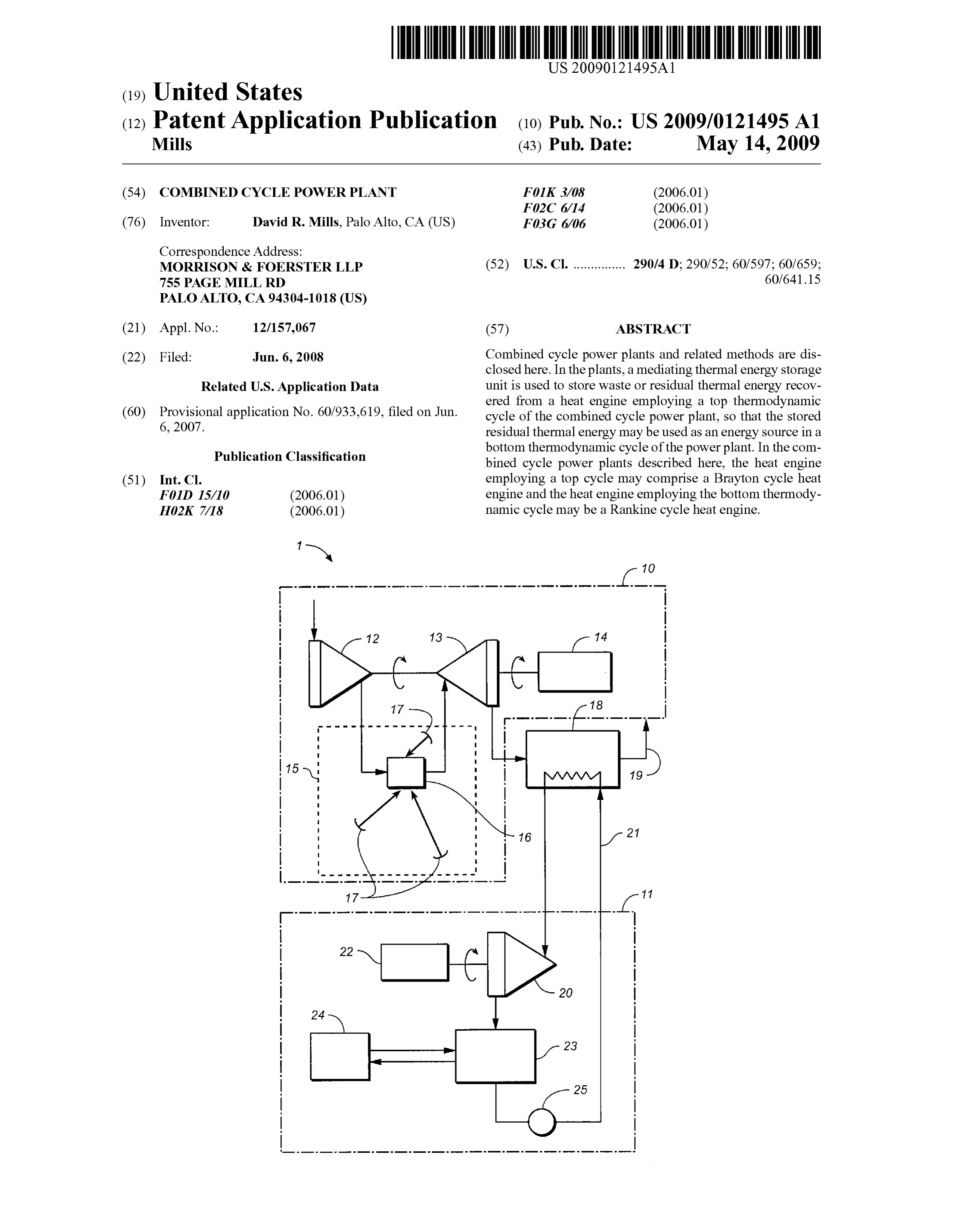
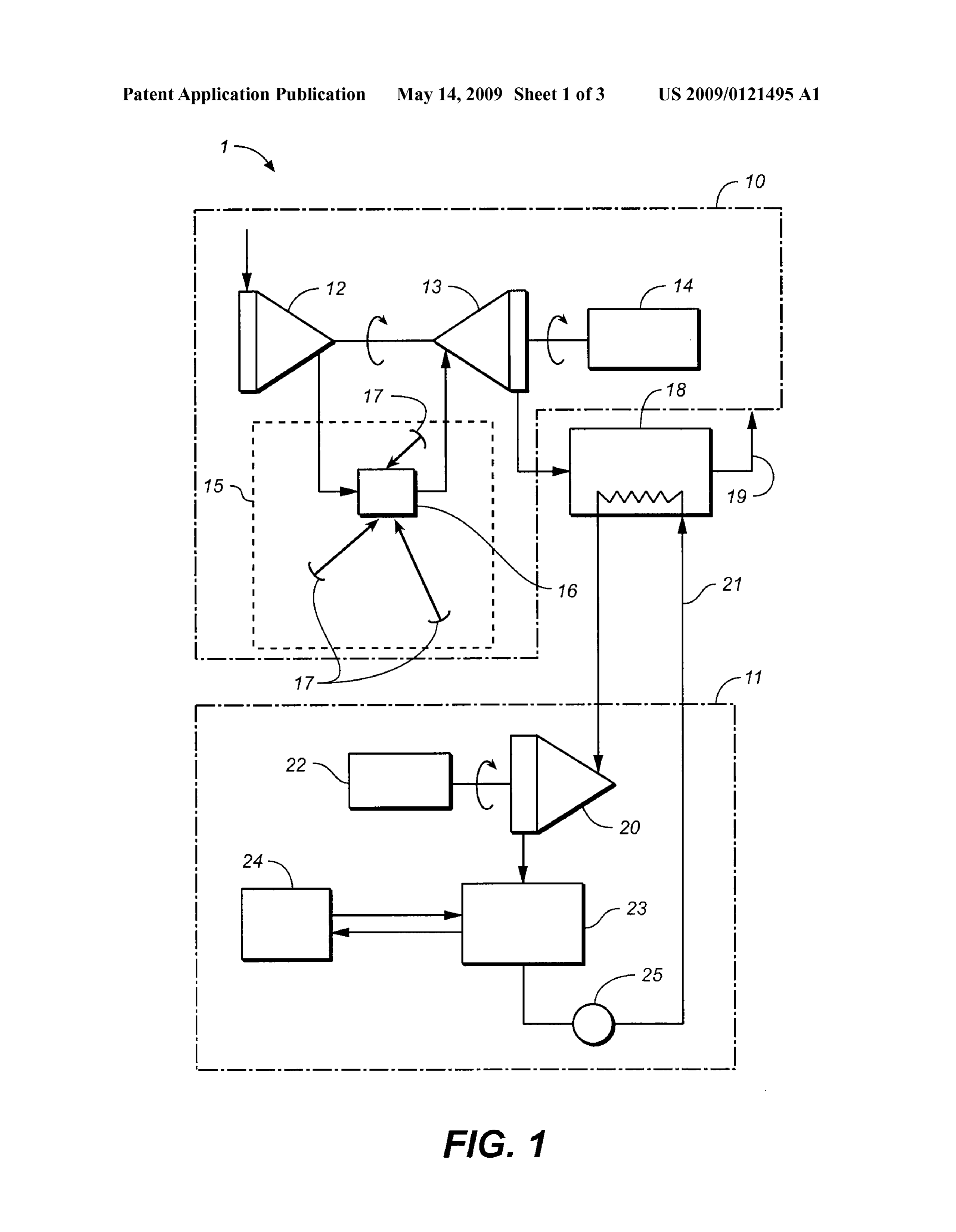
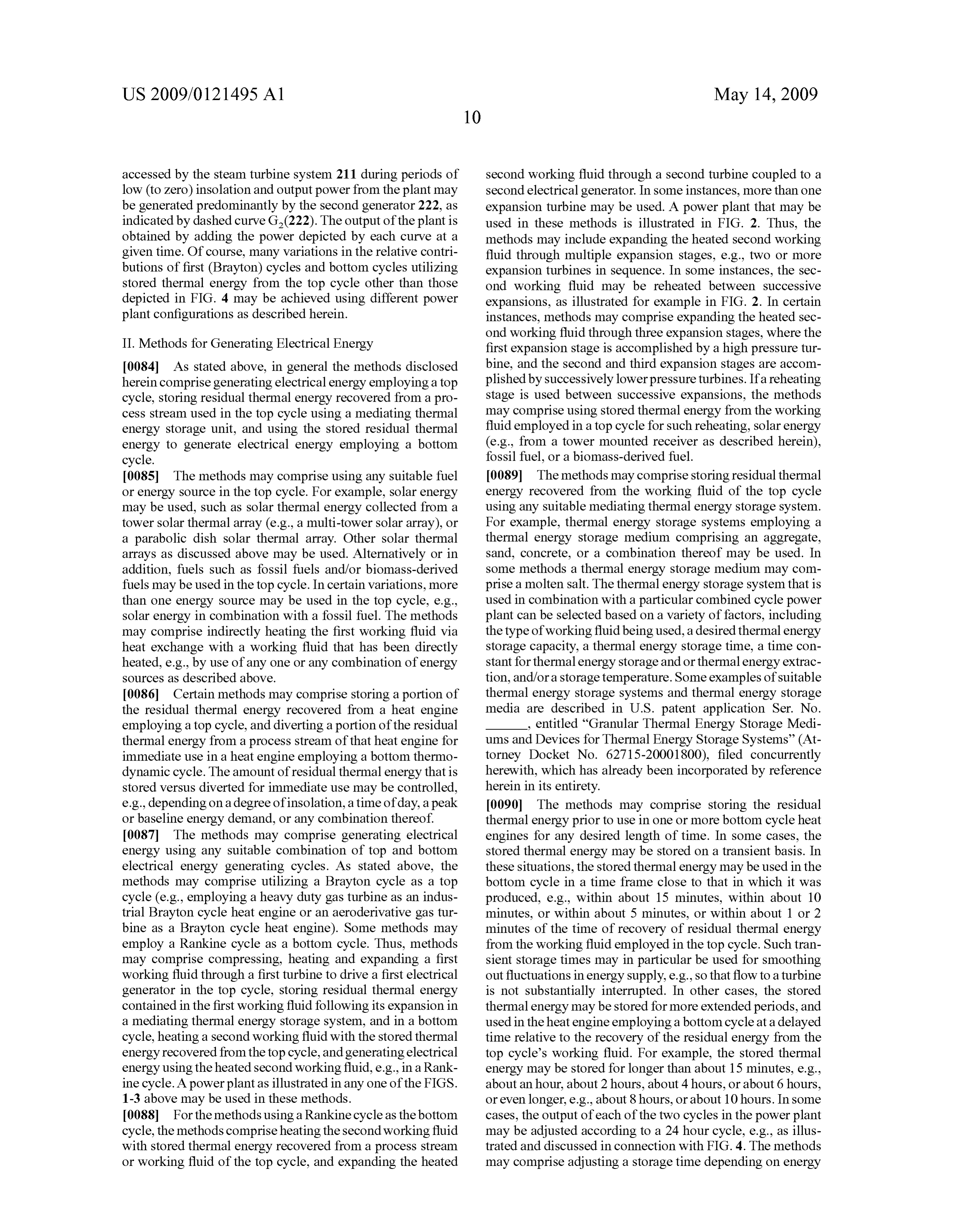
US 2009/012 1495 A1 May 14, 2009
ture gas from the receiver 16 to ground level where the first and U.S. Provisional Patent Application Ser. No. 60/933,574, turbine 13 and first generator 14 might alternatively be entitled “Convective/Radiative Cooling Of Condenser Cool located. ant’ (Attorney Docket No. 62715-3000500), filed Jun. 6, 0063 Having expanded through the gas (first) turbine 13, 2007, each of which is incorporated by reference herein in its at least a portion of the first working fluid may be directed to entirety.
a mediating thermal energy storage system 18 where residual 0068. Still referring to FIG. 1, the second working fluid in thermal energy contained in the first working fluid is released its liquid phase is delivered by a pump 25 from the condenser (by heat exchange) to a thermal energy storage medium as 23 to the thermal energy storage system 18, where stored described herein within the thermal energy storage system 18. thermal energy, and optionally a Supplemental energy source, Then, having expended all (or, at least, a majority) of its is transferred by heat exchange to the second working fluid in acquired energy, the first working fluid may be exhausted to an amount to generate Superheated Steam for delivery to the the atmosphere as indicated by numeral 19. As described steam turbine 20. Thus, first system 10 employing a top above, the power plants may be configured to adjust the thermodynamic cycle provides at least a portion of the ther amount of residual thermal energy that is to be stored, and the mal energy required to power second system 11 having a heat amount of recovered residual thermal energy that is to be engine employing the bottom thermodynamic cycle, and the directed to a turbine employing a bottom cycle for immediate thermal energy storage system 18 provides a key feature to use. Thus, a control valve (not shown) may be used to adjust maintain operation of the combined cycle system. That is, the an amount (if any) of the first working fluid containing thermal energy storage system 18 provides for operation of residual thermal energy that may be directed to the mediating the second system 11 when, for example, the output from the thermal energy storage system 18, and an amount (if any) that first system 10 is not adequate to meet load demand or insuf may be directed to a turbine employing a bottom thermody ficient Solar radiation is available to energise the first system namic cycle 11 for immediate use. 10 at a required level.
0064. As indicated earlier in this specification, the thermal 0069 FIG. 2 illustrates one possible implementation or energy storage system 18 may employ any one of a number of variation of a power plant such as that illustrated in FIG. 1. storage media of a type having the capacity to absorb, retain Ancillary equipment or features such as valves and metering and then release thermal energy in any desired duty cycle, devices as would normally be included in Such a plant have e.g., a duty cycle extending over approximately 24 hours, or been omitted from the drawing as being unnecessary for an a different period of time. understanding of the invention.
0065. The depicted power plant comprises a second tur 0070. In the embodiment of the combined cycle power bine 20 (e.g., a steam turbine) through which a second work plant 200 illustrated in FIG. 2, the first working fluid, in the ing fluid is directed by way of a closed loop 21. The second form of ambient air, is passed through an air conditioning working fluid comprises condensed water, Saturated vapour (i.e., filtering and cooling) system 226 and is delivered to the (wet steam) and, in most variations, Superheated Steam, turbo-compressor 212. Following compression, the first depending upon its position within the loop 21. Superheated working fluid is heated in the heating system 215 and is or Saturated Steam is admitted to and expands through the delivered to the first turbine 213, through which it expands to turbine 20 and the resultant expended energy is applied to impart rotary drive to the first turbine 213 and the coupled first drive a second electric generator 22. Although not shown, the generator 214.
electrical output from the first generator 14 and the second 0071. The heating system 215 in the embodiment shown generator 22 may each be delivered to an electricity Supply in FIG. 2 also may, but need not comprise a solar energy grid. collector system as an energy source. Any energy source may 0066 Having expanded through the steam turbine 20, be used in a heating system of the top cycle in addition to or residual steam/vapour is delivered to a condenser 23 where in place of solar energy, e.g., a fossil fuel or a biomass-derived sensible and latent heat is removed by a condenser coolant fuel. If a solar energy collector system is used, it may com fluid that is recirculated through a condenser fluid coolant prise one or more tower-mounted cavity-type receivers 216 to system 24. The condenser may comprise any one of a number which concentrated solar radiation is reflected by a field of of different types of condensers, including shell-and-tube reflectors 217, which may be for example be any heliostats as condensers and direct contact condensers, but in certain described herein or otherwise known (e.g., fixed vertical axis variations a condenser may comprise a direct contact con heliostats or fixed horizontal axis heliostats). As in the case of denser in which coolant fluid is contacted with the second the FIG. 1 embodiment, the field of reflectors 217 normally working fluid. The condenser coolant fluid cooling system comprises many hundreds of reflectors (e.g., heliostats). In may embody evaporative cooling, forced air cooling, Subter certain variations, in the interest of achieving increased ranean heat exchange, or any combination thereof. ground coverage with the heliostats 217, each heliostat may 0067. In an alternative (not illustrated) embodiment, air comprise one having a fixed horizontal axis, for example as cooled condensing may be employed for condensing the out disclosed in Australian Provisional Patent Application No. put vapour from the turbine 20. In such case, and if the plant 2007900391, dated Jan. 29, 2007 and International Patent comprises a solar energy collector system such as that indi Application No. PCT/AU2008/, entitled “Solar Energy Col cated by reflector field 15, a plurality of air cooled condensers lector Heliostats' filed Jan. 29, 2008, each of which has may be positioned within the reflector field 15 and draw already been incorporated by reference herein in its entirety. coolant air from a Zone shaded by the reflectors 17. Non Under some circumstances, a collision avoiding Solar track limiting examples of air cooled condensers that may be used ing system of the type disclosed in Australian Provisional in connection with the power plants disclosed herein are Patent Application No. 2007900390, dated Jan. 29, 2007 and provided in U.S. patent application Ser. No. entitled International Patent Application No. PCT/AU2008/000096, “Convective/Radiative Cooling Of Condenser Coolant’ (At dated Jan. 29, 2008, may be employed for driving the torney Docket No. 62715-2000500), filed Jun. 2008, heliostats.
Page 12
US 2009/012 1495 A1 May 14, 2009
0072 The receiver 216 in this embodiment may include a may bypass the storage system 218 for immediate use in the Solar radiation absorbing core which comprises, e.g., is com bottom cycle 211. The thermal energy storage system 218 posed primarily of fabricated from, or formed from a refrac may be any Suitable thermal energy storage system as tory material. The term “refractory material' is to be under described herein, otherwise known, or later developed, but in stood in the context of the present application as one that is this particular embodiment may comprise a Subterranean Substantially opaque to Solar radiation and remains Substan storage system that has fluid transport conduits buried in a tially stable (physically and/or chemically) when exposed to matrix of aggregated conductive earthen material and option temperatures (for example of the order of about 800° C. to ally using metal fins. Examples of such thermal energy Stor about 1200° C., or about 800° C. to about 2000° C., e.g., at age systems are disclosed in U.S. Provisional Patent Appli least about 800° C., at least about 1000° C., at least about cation Ser. No. 60/933,637, filed Jun. 6, 2007, entitled 1200° C., at least about 1400° C., at least about 1600° C., at “Thermal Energy Storage System and Thermal Power Plant least about 1800° C., at least about 2000° C. that may be Incorporating Such System’ (Attorney Docket No. 62715 established with absorption of concentrated solar radiation. 3000900) and U.S. patent application Ser. No. s Such “refractory material may, for example, comprise a entitled “Granular Thermal Energy Storage Mediums and refractory metal, a ceramic, or a cermet. Refractory materials Devices for Thermal Energy Storage Systems’ (Attorney may comprise e.g. alumina, silica, carbon, magnesia, Zirco Docket No. 62715-2001800), filed concurrently herewith, nia, silicon carbide, titanium carbide, tantalum carbide, chro mium carbide, niobium carbide, Zirconium carbide, molyb each of which is incorporated by reference herein in its denum disilicide, calcium oxide, graphite, chromite, entirety. The first working fluid may be exhausted to the dolomite, magnesite, quartzite, aluminium silicate, tungsten, atmosphere from the thermal energy storage system 218 at a molybdenum, niobium, tantalum, rhenium, beryllium, and relatively low temperature, as indicated by numeral 219. combinations thereof. The core may be formed or otherwise 0075. In some variations, the turbine employing a bottom provided with a downwardly facing cavity 216a into which thermodynamic cycle may comprise multiple stages. Thus, concentrated solar radiation is reflected by the reflectors 217 the steam cycle system within the FIG. 2 embodiment of the (e.g., heliostats). In these receivers, the core may absorb power plant comprises a two-stage turbine 220a, 220 b (e.g., incident solar radiation, whereby the absorbed radiation is steam turbine) through which the second working fluid is converted to thermal energy stored in the core. Thus, in cer directed by way of two series-circuit loops 221a and 221b, the tain variations, a receiver 216 may comprise passages 216b in former of which provides a primary heating stage and latter of or surrounding the core through which the first working fluid which incorporates an inter-turbine reheating stage. The sec may be directed following compression to extract stored ther ond working fluid comprises condensed water, Saturated mal energy from the core, and the heated compressed first vapour and Superheated Steam, depending upon its position working fluid may be subsequently admitted to the turbine within the loops 221a and 221b. Superheated steam is admit 213. An aperture 216d of the cavity 216a may be substantially ted to and expands through the turbine stages and the resultant parallel to the ground, so as to reduce or eliminate convective expended energy is applied to drive the second electric gen thermal energy losses from the cavity 216.a. Non-limiting erator 222. Although the multi-stage steam turbine in FIG. 2 examples of receivers comprising refractory cores that may is depicted as a two-stage turbine with an intervening reheat be used in connection with Such variations of powerplants are ing stage, any other type of multi-stage turbine may be used in provided in U.S. patent application Ser. No. entitled the power plants described herein, e.g., a multi-stage turbine “Integrated Solar Receiver-Storage Units.” (Attorney Docket that operates without an intervening reheating stage, e.g., a No. 62715-2000400), filed concurrently herewith and U.S. three-stage turbine in which the first stage turbine is a high Provisional Patent Application Ser. No. 60/933,574, filed Jun. pressure turbine, the second stage turbine operates at reduced 6, 2007, each of which has already been incorporated by pressures relative to the first turbine, and the final stage tur reference herein in its entirety. The receivers may also be bine operates at still lower pressure. angled to more closely face the field if of the volumetric type. 0076. Having expanded through both of the steam turbine 0073. The power plant may optionally comprise a thermal stages 220a and 220b, residual steam/vapour is delivered to energy storage unit 216c configured to store heat from the the condenser 223 where sensible and latent heat is removed heated compressed first working fluid before expansion, by a condenser coolant fluid that is recirculated through a which may be integrated into (e.g., in a refractory core of condenser fluid coolant system 224. As in the case of the FIG. receiver 216 as described above), or may be provided sepa 1 embodiment, the condenser may comprise any one of a rately from the receiver. If a thermal energy storage unit 216c number of different types of condensers but, as indicated, in is provided, it may be any thermal energy storage system as Some variations the condenser may comprise a direct contact described herein, otherwise known, or later developed. The condenser in which coolant fluid is contacted with the second thermal energy storage unit, if present, may be used to com working fluid. The condenser coolant fluid cooling system pensate for transient interruptions to or reductions in the may in some instances comprise a Subterranean cooling sys delivery of solar energy to the first turbine 213. tem of the type disclosed in International Patent Application 0074 Having expanded through the turbine 213, at least a No. PCT/AU2007/000268, filed Mar. 2, 2007, which is portion of the first working fluid may be directed into and hereby incorporated herein by reference in its entirety. through the thermal energy storage system 218 where 0077. The second working fluid in its liquid phase is deliv residual thermal energy contained in the first working fluid is ered by the pump 225 from the condenser 223 to the thermal released (by heat exchange) to the thermal energy storage energy storage system 218 by way of a condensate reservoir medium within the thermal energy storage system. As 227. The reservoir 227 may accommodates fluctuations in the described in connection with FIG. 1 above, the power plant level of the second working fluid in the thermal energy stor may comprise a control valve (not shown) for adjusting an age system and/or provide for balancing of transport of the amount (if any) of the first working fluid following expansion second working fluid throughout the water-steam circuit.
Page 13
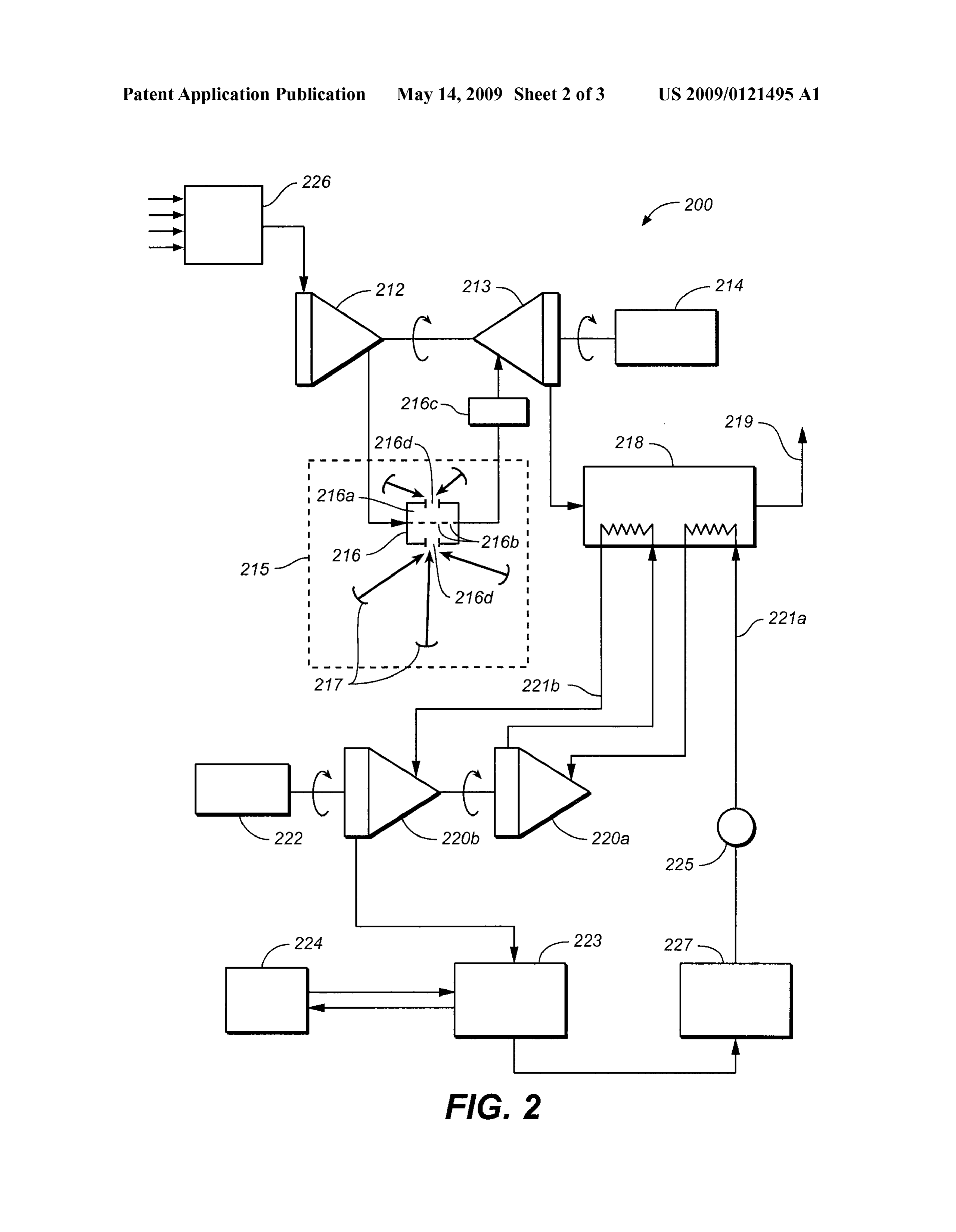
US 2009/012 1495 A1 May 14, 2009
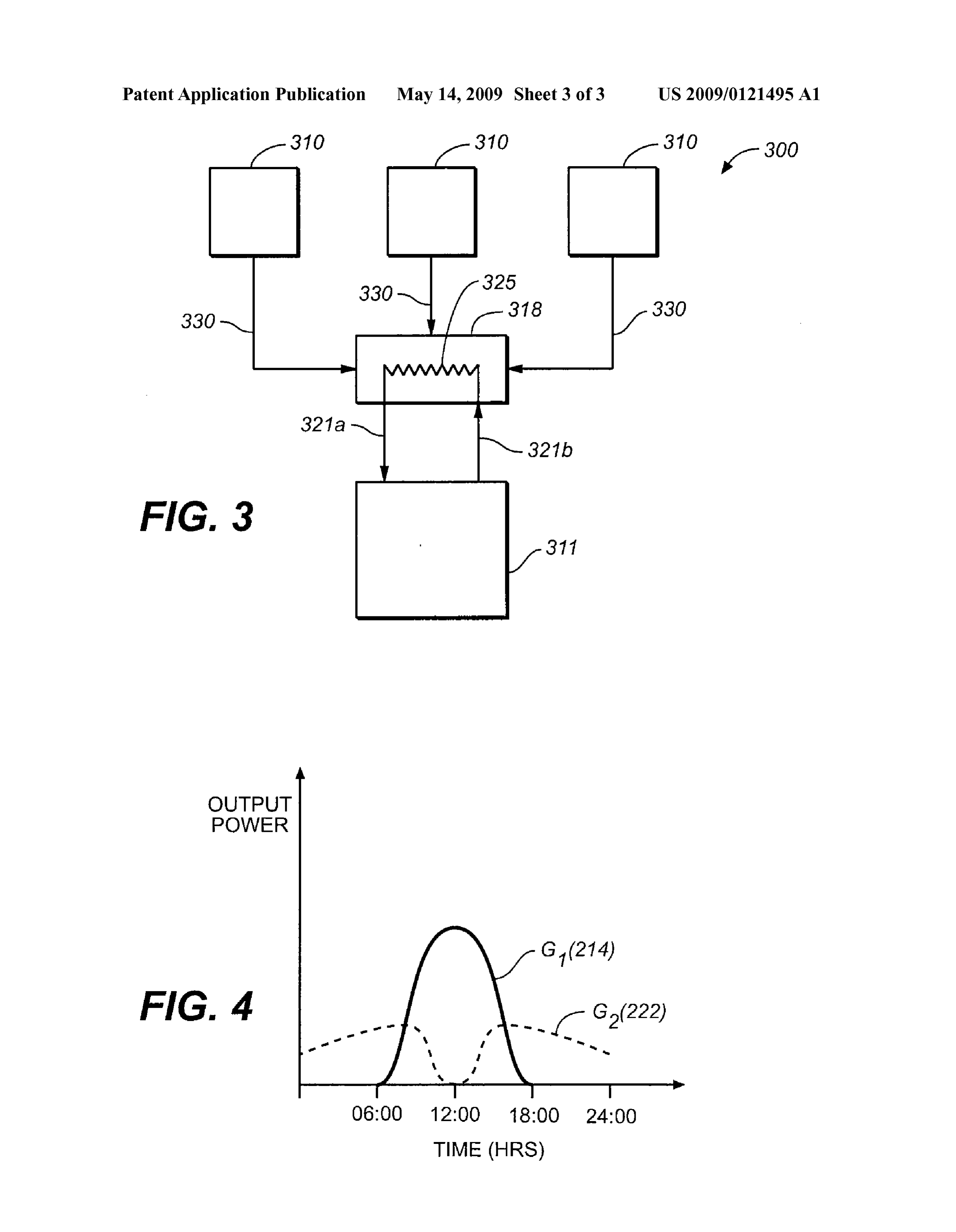
0078. As in the case of the FIG. 1 embodiment, thermal I0081 Referring now to FIG.3, an example of a combined energy that is stored in the thermal energy storage system 218 cycle powerplant 300 is illustrated which comprises multiple is transferred by heat exchange to the second working fluid in first energy generating heat engines 310. The engines 310 the primary stage and reheating stage (if present), and Super may be any suitable heat engines, may be the same or differ heated Steam is generated for delivery to the respective steam ent, and may be powered using the same or different energy turbine stages 220a and 220b. Sources, as described above. In some instances, the engines 0079. In certain variations of the power plants, it may be 310 may employ a Brayton cycle, e.g., as illustrated as heat desired to generally match the amount of residual heat Sup engine 10 in FIG. 1 or heat engine 210 in FIG. 2. Each of the plied by the first working fluid of a top cycle to the amount of engines 310 may generate electricity, e.g., by expansion of a heat required to run the heat engine employing a second cycle heated working fluid through a turbine coupled to a generator to, e.g., increase an overall efficiency of the plant. For as described above. Residual thermal energy may be recov example, in certain situations it may be desired to use a ered from those engines, e.g., after expansion of a heated relatively high capacity Rankine cycle heat engine. Any type working fluid. Some or all of the recovered residual thermal of Brayton cycle heat engine may be used to feed into the energy from each engine 310 may be conveyed to a mediating Rankine cycle heat engine, but in Some cases it may be ben thermal energy storage unit 318, as indicated by arrows 330. eficial to use an industrial Brayton cycle engine Such as a The thermal energy storage unit 318 may be configured to heavy duty gas turbine, as industrial Brayton cycle heat accumulate and store residual energy from Some or all of the engines generally have higher capacity than aeroderivative engines 310. The stored thermal energy may then be used to turbines employing a Brayton cycle. However, the residual power a heat engine employing a bottom thermodynamic thermal energy recovered from an industrial Brayton cycle cycle 311, e.g., a Rankine cycle heat engine (e.g. turbine). In engine may have a lower temperature than that of an aero this particular variation, the heat engine 311 is depicted as a derivative cycle. Therefore, without a mediating thermal closed loop cycle in which a second working fluid (e.g., energy storage unit to build up residual thermal energy from steam, water, or a steam/water mixture as described above) an industrial Brayton cycle engine, the Rankine cycle engine extracts thermal energy from the thermal energy storage unit may require larger amounts of auxiliary fuel to generate 318 via a heat exchanger 325. The heated second working Superheated Steam Suitable for driving a steam turbine, which fluid may be then expanded to drive a turbine coupled to a may in turn lower overall plant efficiency. However, with the generator.
plants described herein, residual thermal energy from the I0082 In the combined cycle power plants as illustrated in working fluid of the top cycle may be accumulated and built FIG. 3, any combination of heat engines upstream from the up over time in the mediating thermal energy storage unit. mediating thermal energy storage unit may be used, and any The amount of residual energy accumulated over time may be downstream heat engine or engines may be used. In some Sufficient to generate Superheated Steam from an industrial cases, an overall efficiency, a peak output, or a base output of Brayton cycle heat engine without the need for, or with a the plant may be adjusted by tuning some or all of its energy reduced need for, auxiliary energy sources in the heat engine generating components. As one illustration, the combined employing the bottom thermodynamic cycle to produce waste heat of the heat engines 310 may be matched with Superheated Steam. Thus, the combined cycle power plants energy requirements for one or more heat engines of the incorporating mediating thermal energy storage systems may bottom cycle 311 to improve efficiency. For example, the set allow coupling of a high capacity industrial Brayton cycle of heat engines 310 may comprise aeroderivative gas engines, with a high capacity Rankine cycle, and still maintain a high and by feeding heat from multiple aeroderivative gas engines overall efficiency, e.g., about 60%, about 65%, about 70%, or into a single Rankine cycle heat engine, the capacities of the even higher. top and bottom energy generating systems of the combined 0080 Additional schemes or power plant configurations cycle power plant may be better matched, which may lead to may be used to increase one or more performance parameters increased overall efficiency. Further, as described above, Such as efficiency in the powerplants described here. In some Some of the residual energy from one or more of the heat variations of combined cycle power plants, the top cycle may engines employing top thermodynamic cycles 310 may be be one of a set of multiple energy generating cycles, and waste used directly in one or more heat engines employing the thermal energy from the set may be used to power a heat bottom thermodynamic cycle (i.e., thermal energy storage engine employing a bottom thermodynamic cycle. In these unit 318 may be bypassed). An amount of energy that is stored variations, the mediating thermal energy storage unit may be in the mediating thermal energy storage unit may be varied, configured to accumulate residual thermal energy from some e.g., to tune an output of the power plant to produce a desired or all of the energy generating cycles in the set. Any or all of amount of peak or baseline power or to Smooth out fluctua the energy generating cycles in the set may comprise Brayton tions such as those due to periods of low insolation for Solar cycles heat engines, e.g., one or more heavy duty gas turbines powered plants.
or one or more aeroderivative gas turbines. The energy gen I0083 FIG. 4 provides a graphical representation of the erating cycles in the set may, but need not be, of the same type, operation of a combined cycle power plant as described capacity, and/or efficiency. Further, the energy generating herein, e.g., a power plant as shown in any one of FIGS. 1-3, cycles in the set may utilize the same or different energy over a twenty-four hour period. Referring for example to Sources, e.g., some or all may be solar powered, or driven by power plant 200 in FIG. 2, during the daytime period from fossil fuel or biomass-derived fuel. The heat pump of a bot about 06:00 to 18:00, output power from the plant (indicated tom cycle may for example comprise a Rankine cycle heat by solid curve G (214)) may be generated predominantly by pump using steam as a working fluid as described herein. The the first generator 214 in the (Brayton cycle) gas turbine mediating thermal energy storage unit used in these plants system 210, peaking during a period of maximum insolation may be any thermal energy storage unit as described herein, at approximately 12:00. Energy that is stored in the energy otherwise known, or later developed. storage system 218 during high levels of insolation may be
Page 14
US 2009/012 1495 A1 May 14, 2009
accessed by the steam turbine system 211 during periods of second working fluid through a second turbine coupled to a low (to Zero) insolation and output power from the plant may second electrical generator. In some instances, more than one be generated predominantly by the second generator 222, as expansion turbine may be used. A power plant that may be indicated by dashed curve G(222). The output of the plant is used in these methods is illustrated in FIG. 2. Thus, the obtained by adding the power depicted by each curve at a methods may include expanding the heated second working given time. Of course, many variations in the relative contri fluid through multiple expansion stages, e.g., two or more butions of first (Brayton) cycles and bottom cycles utilizing expansion turbines in sequence. In some instances, the sec stored thermal energy from the top cycle other than those ond working fluid may be reheated between successive depicted in FIG. 4 may be achieved using different power expansions, as illustrated for example in FIG. 2. In certain plant configurations as described herein. instances, methods may comprise expanding the heated sec ond working fluid through three expansion stages, where the
II. Methods for Generating Electrical Energy first expansion stage is accomplished by a high pressure tur 0084 As stated above, in general the methods disclosed bine, and the second and third expansion stages are accom herein comprise generating electrical energy employing a top plished by successively lower pressure turbines. If a reheating cycle, storing residual thermal energy recovered from a pro stage is used between Successive expansions, the methods cess stream used in the top cycle using a mediating thermal may comprise using stored thermal energy from the working energy storage unit, and using the stored residual thermal fluid employed in a top cycle for Such reheating, Solar energy energy to generate electrical energy employing a bottom (e.g., from a tower mounted receiver as described herein), cycle. fossil fuel, or a biomass-derived fuel. 0085. The methods may comprise using any suitable fuel I0089. The methods may comprise storing residual thermal or energy source in the top cycle. For example, Solar energy energy recovered from the working fluid of the top cycle may be used, such as Solar thermal energy collected from a using any Suitable mediating thermal energy storage system. tower Solar thermal array (e.g., a multi-tower Solar array), or For example, thermal energy storage systems employing a a parabolic dish solar thermal array. Other solar thermal thermal energy storage medium comprising an aggregate, arrays as discussed above may be used. Alternatively or in sand, concrete, or a combination thereof may be used. In addition, fuels such as fossil fuels and/or biomass-derived Some methods a thermal energy storage medium may com fuels may be used in the top cycle. In certain variations, more prise a molten salt. The thermal energy storage system that is than one energy source may be used in the top cycle, e.g., used in combination with a particular combined cycle power solar energy in combination with a fossil fuel. The methods plant can be selected based on a variety of factors, including may comprise indirectly heating the first working fluid via the type of working fluid being used, a desired thermal energy heat exchange with a working fluid that has been directly storage capacity, a thermal energy storage time, a time con heated, e.g., by use of any one or any combination of energy stant for thermal energy storage and orthermal energy extrac Sources as described above. tion, and/or a storage temperature. Some examples of suitable I0086 Certain methods may comprise storing a portion of thermal energy storage systems and thermal energy storage the residual thermal energy recovered from a heat engine media are described in U.S. patent application Ser. No. employing a top cycle, and diverting a portion of the residual entitled “Granular Thermal Energy Storage Medi thermal energy from a process stream of that heat engine for ums and Devices for Thermal Energy Storage Systems’” (At immediate use in a heat engine employing a bottom thermo torney Docket No. 62715-20001800), filed concurrently dynamic cycle. The amount of residual thermal energy that is herewith, which has already been incorporated by reference stored versus diverted for immediate use may be controlled, herein in its entirety.
e.g., depending on a degree of insolation, a time of day, a peak 0090 The methods may comprise storing the residual or baseline energy demand, or any combination thereof. thermal energy prior to use in one or more bottom cycle heat 0087. The methods may comprise generating electrical engines for any desired length of time. In some cases, the energy using any Suitable combination of top and bottom stored thermal energy may be stored on a transient basis. In electrical energy generating cycles. As stated above, the these situations, the stored thermal energy may be used in the methods may comprise utilizing a Brayton cycle as a top bottom cycle in a time frame close to that in which it was cycle (e.g., employing a heavy duty gas turbine as an indus produced, e.g., within about 15 minutes, within about 10 trial Brayton cycle heat engine or an aeroderivative gas tur minutes, or within about 5 minutes, or within about 1 or 2 bine as a Brayton cycle heat engine). Some methods may minutes of the time of recovery of residual thermal energy employ a Rankine cycle as a bottom cycle. Thus, methods from the working fluid employed in the top cycle. Such tran may comprise compressing, heating and expanding a first sient storage times may in particular be used for Smoothing working fluid through a first turbine to drive a first electrical out fluctuations in energy Supply, e.g., so that flow to a turbine generator in the top cycle, storing residual thermal energy is not substantially interrupted. In other cases, the stored contained in the first working fluid following its expansion in thermal energy may be stored for more extended periods, and a mediating thermal energy storage system, and in a bottom used in the heat engine employing a bottom cycle at a delayed cycle, heating a second working fluid with the stored thermal time relative to the recovery of the residual energy from the energy recovered from the top cycle, and generating electrical top cycle's working fluid. For example, the stored thermal energy using the heated second working fluid, e.g., in a Rank energy may be stored for longer than about 15 minutes, e.g., ine cycle. A powerplantas illustrated in any one of the FIGS. about an hour, about 2 hours, about 4 hours, or about 6 hours, 1-3 above may be used in these methods. or even longer, e.g., about 8 hours, or about 10 hours. In some 0088 For the methods using a Rankine cycle as the bottom cases, the output of each of the two cycles in the power plant cycle, the methods comprise heating the second working fluid may be adjusted according to a 24 hour cycle, e.g., as illus with stored thermal energy recovered from a process stream trated and discussed in connection with FIG. 4. The methods or working fluid of the top cycle, and expanding the heated may comprise adjusting a storage time depending on energy
Page 15
US 2009/012 1495 A1 May 14, 2009
demand and energy Supply, e.g., adjusting a storage time of first working fluid indirectly, for example by way of an inter the recovered residual energy so that a combined output of the mediate heat exchange fluid. Optionally, the methods may top and bottom cycles meets a fluctuating demand, a baseline effect direct heating of the first working fluid by the receiver, demand, and/or a peak demand, e.g., even during periods of for example by channelling the fluid through the receiver for low insolation for a Solar powered plant. absorption of thermal energy that is generated by absorption 0091. The methods may include adjusting a capacity of the of concentrated Solar energy within a cavity of the receiver. heat engines employing the top and/or bottom cycles to The receiver used in these methods may be any suitable increase overall efficiency or another performance metric for receivers, and in Some instances a receiver used may com the combined cycle system. For example, the top cycle heat prise a refractory core that can absorb incident Solar radiation engine may comprise an industrial Brayton cycle engine, e.g. and convert the radiation to thermal energy and store that a heavy duty gas turbine. In these instances, the methods may thermal energy for later use, e.g., as described in U.S. patent comprise utilizing Steam as a second working fluid in the application Ser. No. entitled “Integrated Solar bottom cycle, and heating that steam to a temperature below Energy Receiver-Storage Units’ (Attorney Docket No. that required by most superheated steam turbines (400-500 62715-2000400), filed concurrently herewith, and already C). In this case a lower temperature turbine similar to nuclear incorporated herein by reference in its entirety. or geothermal designs (200 C-320 C) may be used at some 0094. This disclosure is illustrative and not limiting. Fur cost in bottom cycle efficiency. Accumulated, stored thermal ther modifications will be apparent to one skilled in the art in energy may then be used to drive a steam turbine employing light of this disclosure and Such modifications are intended to the bottom cycle. These methods may be used in particular in fall within the scope of the appended claims. Each publication instances in which it is desired to increase a capacity of the and patent application cited in the specification is incorpo heat engines of a top cycle, or to use a lower temperature rated herein by reference in its entirety as if each individual storage form. In other variations, the top cycle heat engine publication or patent application were specifically and indi may comprise anaeroderivative gasturbine, which may allow vidually put forth herein.
heating the steam to a temperature at or above that required to What is claimed is:
use Super heated Steam, e.g., in a temperature range from about 700° C. to about 800° C. 1. A method of generating electrical energy, the method comprising:
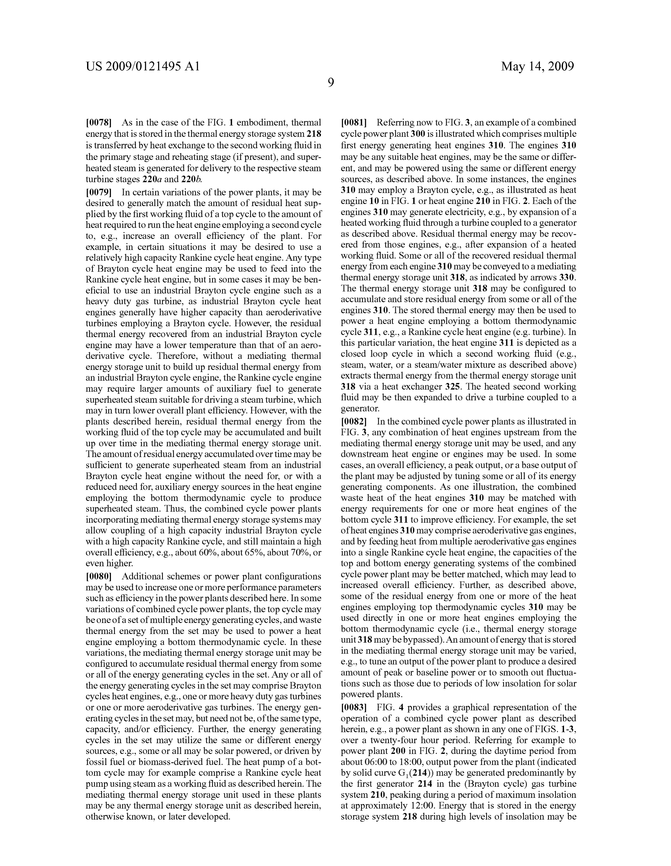
0092. The methods for generating electrical energy may employing a top thermodynamic cycle to generate electri utilize other thermal energy storage schemes. For example, cal energy and residual thermal energy; certain methods may comprise storing at least a portion of storing the residual thermal energy; and heat from the thermal fluid used in the top cycle, before using the stored residual thermal energy to generate elec expanding that fluid to generate electricity. Thus, methods for trical energy in a bottom thermodynamic cycle. generating energy may include any combination of thermal energy storage in the top cycle and/or before use in one or 2. The method of generating electrical energy of claim 1, more bottom cycles. The methods may include storing heated the method comprising:
working fluids using any appropriate thermal energy storage compressing, heating and expanding a first working fluid to system, e.g., by placing a pipe manifold or a vessel in thermal generate electrical energy in the top thermodynamic contact with a thermal energy storage medium comprising cycle;
aggregate, Sand, concrete, a molten salt or a combination storing residual thermal energy contained in the first work thereof, as described herein. In certain variations, the hot ing fluid following expansion; and pressurized working fluid may be stored in a pressurized heating a second working fluid with the stored thermal vessel that may for example be placed underground. energy and generating electrical energy using the heated 0093. If solar energy is to be used to power a top cycle heat second working fluid in the bottom thermodynamic engine or as a Supplementary energy source for a bottom cycle.
cycle heat engine, certain methods may comprise heating the 3. The method of claim 1, comprising utilizing Solar energy appropriate working fluid by heat exchange in at least one in the top thermodynamic cycle.
receiver to which solar radiation is reflected from a field or 4. The method of claim 3, comprising using Solar energy multiple fields of reflectors. Examples of power plants collected from a high concentration central receiver type Solar employing such solar heated receivers are illustrated in FIGS. array (e.g., a multi-tower Solar array), or a parabolic dish Solar 1 and 2. Although this method of heating a working fluid array, using Solar energy is described in connection with the first 5. The method of claim 1, comprising storing a portion of working fluid, it should be understood that a second working the residual thermal energy for use in the bottom thermody fluid in a bottom cycle may be similarly heated, e.g., as an namic cycle at a delayed time, and diverting a portion of the auxiliary energy source to Supply heat in addition to that residual thermal energy for immediate use in the bottom provided by residual thermal energy recovered from a process thermodynamic cycle.
stream of the top cycle, or to heat a reheating stage between 6. The method of claim 1, comprising adjusting a storage Successive expansions. Thus, the first working fluid may be time of the residual thermal energy so that a combined elec heated by heat exchange in at least one receiver to which Solar trical output of heat engines employing the top and bottom radiation is reflected from a field or multiple fields of reflec thermodynamic cycles meets a fluctuating demand. tors. However, in a particular embodiment, the receiver or, if 7. The method of claim 1, comprising adjusting a storage more than one, each of the receivers may optionally comprise time of the residual thermal energy so that a combined elec a tower-mounted cavity-type or volumetric receiver to which trical output of heat engines employing the top and bottom solar radiation is reflected from a field of heliostat-type solar thermodynamic cycles meets a baseline demand. radiation concentrating reflectors. The methods may com 8. The method of claim 1, comprising adjusting a storage prise effecting heat exchange between the receiver and the time of the residual thermal energy so that a combined output
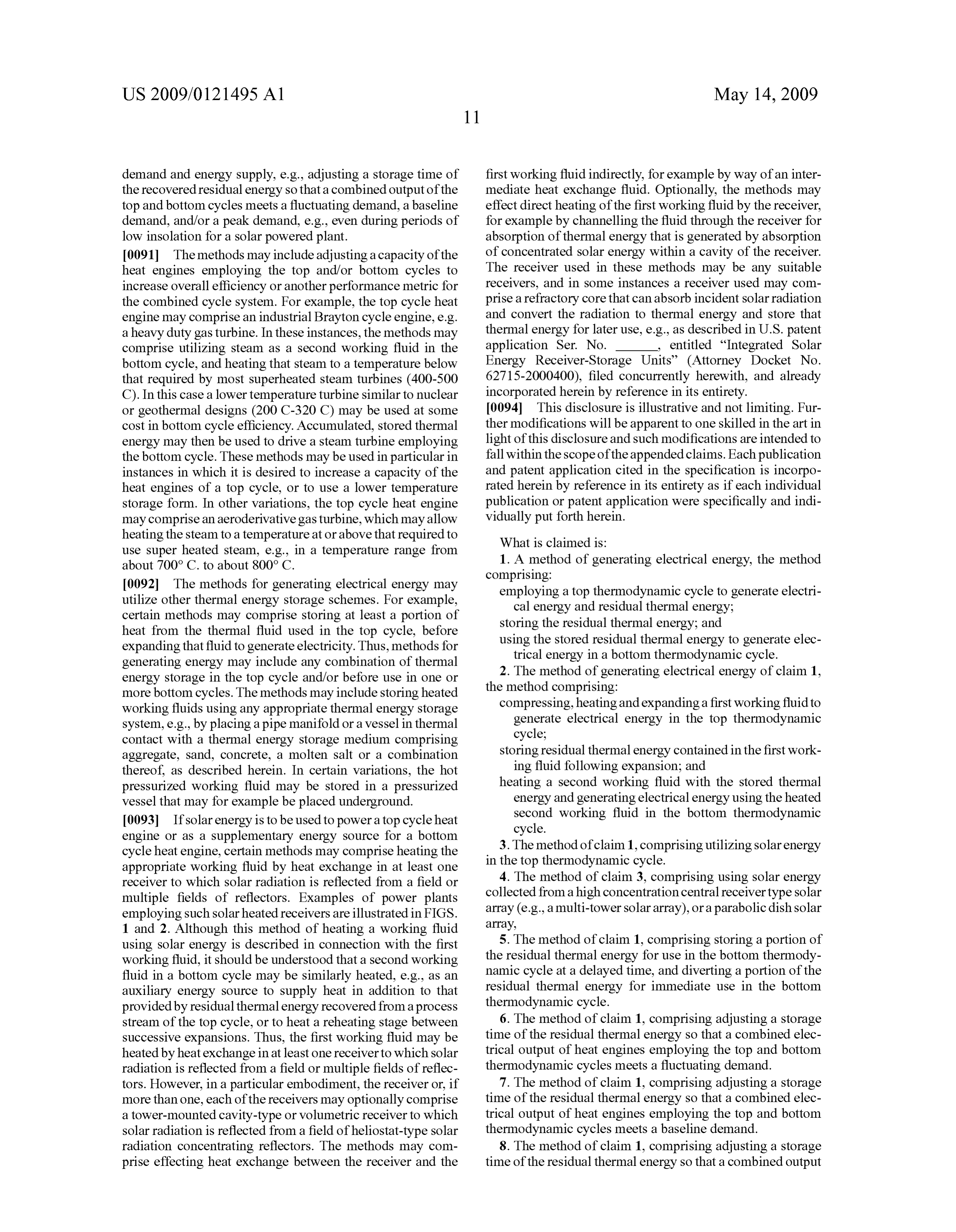
Page 16
US 2009/012 1495 A1 May 14, 2009
of heat engines employing the top and bottom thermody wherein the mediating thermal energy storage unit is con namic cycles meets a peak demand. figured to store residual thermal energy recovered from 9. The method of claim 2, wherein generating electrical the first working fluid following its expansion. energy using the bottom thermodynamic cycle comprises 24. The electrical powerplant of claim 23, wherein the first heating the second working fluid with the stored thermal bottom cycle heat engine comprises: energy recovered from the first working fluid, and expanding a second compressor configured to compress the second the second working fluid to generate electrical energy. working fluid;
10. The method of claim 9, comprising expanding the a second heating stage for heating the compressed second second working fluid in multiple stages through a multi-stage working fluid; and turbine. a second turbine configured to expand the second working 11. The method of claim 10, comprising reheating the fluid to drive a second generator, and second working fluid between expansion stages. wherein the second heating stage uses stored residual ther 12. The method of claim 2, wherein the second working mal energy from the first top cycle heat engine to heat the fluid comprises water, Steam, or steam/water mixture. compressed second working fluid. 13. The method of claim 2, further comprising storing at 25. The electrical power plant of claim 24, wherein the least a portion of the heated compressed first working fluid second turbine comprises multiple expansion stages. before expanding the first working fluid to produce electrical 26. The electrical power plant of claim 25, comprising a energy.
reheating stage configured to reheat the second working fluid between expansion stages.
14. The method of claim 2, further comprising storing at 27. The electrical powerplant of claim 22, wherein the first least a portion of the heated second working fluid before using top cycle heat engine is one of a set oftop cycle heat engines, the heated second working fluid to generate electrical energy. and the mediating thermal energy storage unit is configured to 15. The method of claim 1, comprising providing energy accumulate and store thermal energy from some or all of the used in the top thermodynamic cycle with a fossil fuel or a heat engines in the set.
biomass-derived fuel. 28. The electrical powerplant of claim 27, wherein some or 16. The method of claim 1, configured for a combined all of the heat engines in the set employ a Brayton cycle. efficiency from the top and bottom thermodynamic cycles of 29. The electrical powerplant of claim 22, wherein the first about 65% or greater. top cycle heat engine comprises a heavy duty gas turbine. 17. The method of claim 1, wherein the top thermodynamic 30. The electrical powerplant of claim 22, wherein the first cycle is one of a set of energy generating cycles, and the top cycle heat engine comprises an aeroderivative gas turbine. method comprises accumulating and storing residual energy 31. The electrical powerplant of claim 22, wherein the first from a process fluid of some or all of the cycles in the set and bottom cycle heat engine comprises a Rankine or Kalina using the accumulated Stored residual energy to generate cycle turbine.
electrical energy employing the bottom thermodynamic 32. The electrical power plant of claim 23, wherein the cycle. mediating thermal energy storage unit utilizes a thermal 18. The method of claim 17, wherein some or all of the energy storage medium comprising an aggregate, Sand, con cycles in the set of energy generating cycles comprise Bray crete, a molten salt, or a combination thereof. ton cycles. 33. The electrical power plant of claim 22, having an effi 19. The method of claim 1, comprising using an industrial ciency of about 65% or higher.
Brayton or Ericsson turbine in the top thermodynamic cycle. 34. The electrical power plant of claim 22, configured as a 20. The method of claim 1, comprising using an aero load following power plant.
derivative Brayton or Ericcson turbine in the top thermody 35. The electrical power plant of claim 22, configured to namic cycle. Supply a baseline amount of electrical energy. 21. The method of claim 1, comprising using a Rankine or 36. The electrical power plant of claim 22, configured to Kalina cycle as the bottom thermodynamic cycle. Supply peak amounts of electrical energy. 22. An electrical power plant comprising: 37. The electrical powerplant of claim 22, wherein the first a first top cycle heat engine employing a top thermody top cycle heat engine is configured to be powered with Solar namic cycle configured to generate electrical energy; energy.
a mediating thermal energy storage unit configured to store 38. The electrical powerplant of claim 37, wherein the first residual thermal energy recovered from a first working top cycle heat engine is configured to be heated with Solar fluid of the first top cycle heat engine; and energy produced by a tower Solar array, or a parabolic dish a first bottom cycle heat engine employing a bottom ther Solar array.
modynamic cycle and configured to generate electrical 39. The electrical powerplant of claim 22, wherein the first energy using the stored thermal energy from the medi top cycle heat engine is configured to be heated with a fossil fuel or a biomass-derived fuel.
ating thermal energy storage unit. 40. The electrical power plant of claim 22, further com 23. The electrical powerplant of claim 22, wherein the first prising a top cycle thermal energy storage unit configured to top cycle heat engine comprises: store heat from heated first working fluid prior to its expan a first compressor configured to compress a first working S1O.
fluid; 41. The electrical power plant of claim 24, further com a first heating stage for heating the compressed first work prising a bottom cycle thermal energy storage unit configured ing fluid, to store heated second working fluid prior to its expansion. a first turbine configured to expand the first working fluid to 42. The electrical power plant of claim 23, comprising a drive a first generator, and receiver configured to receive and absorb reflected and con
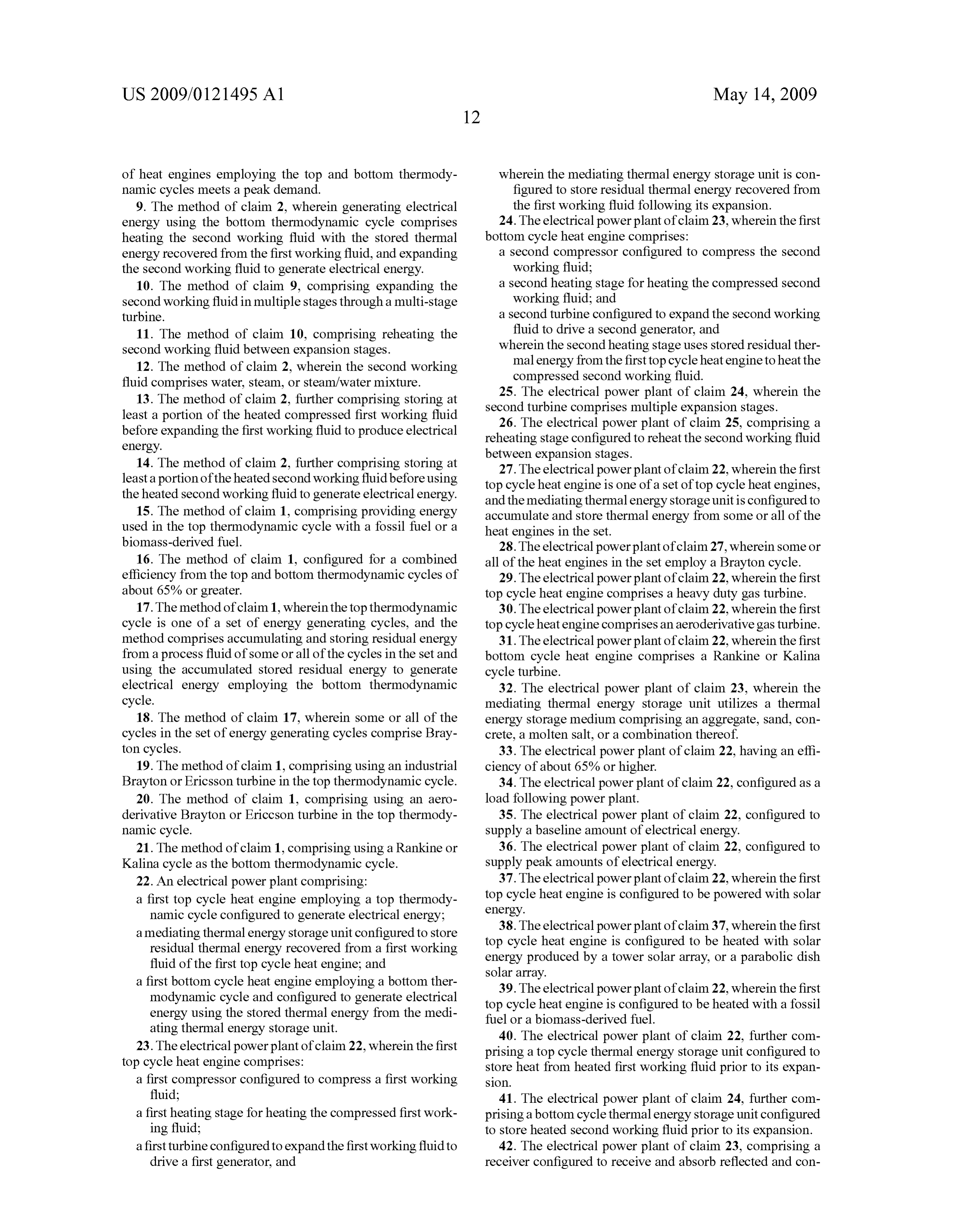
Page 17
US 2009/012 1495 A1 May 14, 2009
centrated solar radiation directed thereto, and to heat at least 48. An electrical power plant comprising means for com one of the top and bottom working fluids. pressing a first working fluid, means for effecting heating of 43. The electrical power plant of claim 42, wherein the the first working fluid following its compression, a first tur receiver comprises a refractory core that is configured to bine couples to a first means for generating electrical energy absorb incident Solar radiation, and to store the resulting and through which the first working fluid is in operation thermal energy. expanded to drive the first generating means, thermal energy 44. The electrical power plant of claim 43, wherein the core storage means arranged to store residual thermal energy con comprises one or more fluid channels in and/or around the tained in the first working fluid following its expansion core to conveya working fluid to facilitate extraction of stored through the first turbine, a second turbine coupled to a second thermal energy from the core. means for generating electrical energy and arranged to 45. The electrical power plant of claim 42, wherein the receive a second working fluid that in operation is expanded receiver is tower mounted. through the second turbine to drive the second generating 46. The electrical power plant of claim 45, wherein the means, and wherein the second working fluid is in operation receiver and the first compressor are tower mounted. heated by use of stored thermal energy extracted from the 47. The electrical power plant of claim 42, comprising an thermal energy storage means.
elevated reflector configured to redirect reflected and concen trated Solar radiation to a ground-mounted receiver. c c c c c
Provenance
- Collection
- Patents citing this work
- Current assignee
- Areva Solar Inc
- Pages
- 17
- Method
- pdftotext (the PDF's own text layer) + pdftoppm 300dpi page scans
- Patent office record
- patents.google.com →
- Source
- Google Patents citing-documents table
- Inventors
- David R. Mills
- Published
- 2009-05-14
- Transcribed from
- patentimages.storage.googleapis.com →