patent · US4131485
Solar energy collector and concentrator
26 December 1978
Page 1 — bibliographic record
United States Patent (19) (11) 4,131,485 Meinel et al. 45) Dec. 26, 1978 (54) SOLAR ENERGY COLLECTOR AND 3,254,342 5/1966 Miller ................................... 343/781 CONCENTRATOR 3,443,086 5/1969 Rikis.................................... 240/41. 3,887,263 6/1975 Thompson ............................... 350/7 (75) Inventors: Aden B. Meinel; Walter B. Meinel, 3,929,510 12/1975 Kittl ...... ... 136/206 both of Tucson, Ariz. 3,988,166 10/1976 Beam ......... ... 136/89 4,024,852 5/1977 L'Esperance voopas 126/270 73 Assignee: Motorola, Inc., Schaumburg, Ill. 4,045,246 8/1977 Mlavsky et al.................. 136/89 PC (21) Appl. No.: 883,558 Primary Examiner-John H. Mack
Assistant Examiner-Aaron Weisstuch 22) Filed: Mar. 6, 1978 Attorney, Agent, or Firm-Robert D. Lott; M. David Related U.S. Application Data Shapiro
Continuation-in-part of Ser. No. 822,583, Aug. 8, 1977, 57 ABSTRACT (63) abandoned. Modular structures for the collection, concentration (51) Int. C.’.......................... H01L 31/04; F24J 3/02 and conversion of solar energy to another usable form 52) U.S. C. ............................... 136/89 PC; 126/270; such as electrical energy. The structures feature three 126/271; 136/206; 350/294 conic section reflective surfaces, two of which focus in (58) Field of Search ........................... 136/89 PC, 206; front of a receiver element and off the axis of the struc 126/270,271; 350/293,294 ture. The third reflective surface is utilized to redirect (56) References Cited that energy which would otherwise miss the receiver element to improve overall efficiency.
3,085,565 4/1963 Macauley ............................. 126/270 33 Claims, 6 Drawing Figures
Page 2
Drawing sheet — no readable text.
Page 3
Drawing sheet — no readable text.
Page 4
Drawing sheet — no readable text.
Page 5
According to another aspect of the invention, a third
SOLAR ENERGY COLLECTOR AND reflector is used to enable stray energy due to aiming CONCENTRATOR inaccuracy to impinge on the receiving element.
FIELD OF THE INVENTION
According to still another aspect of the invention, a third reflector is used to collect energy which would
This application is a continuation-in-part of applica otherwise miss the receiver element because of poor tion Ser. No. 822,583 filed Aug. 8, 1977, now aban collimation of the energy within or without the system. doned. According to a further aspect of the invention, a The invention relates to a three element reflective relatively shallow energy collector is realized which system for collecting and concentrating solar energy on 10 uniformly distributes energy onto a receiving element a receiver surface. which is essentially tangential to the primary reflector. These and other aspects and features of the invention
BACKGROUND OF THE INVENTION will be better understood upon reading of the Detailed Description of the Invention together with inspection
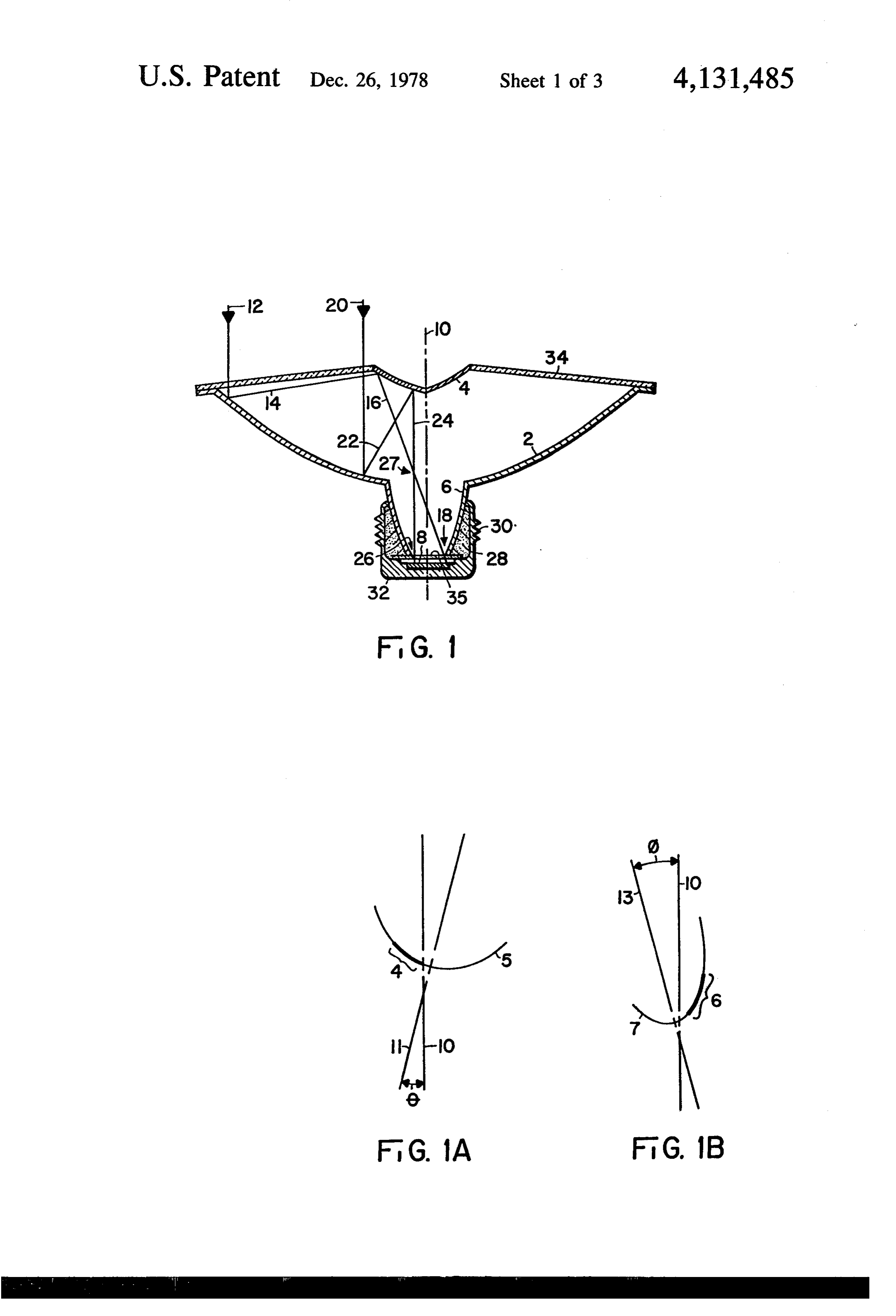
Prior art in the area of solar collection is replete with 15 of examples of the use of folded reflective optical systems. the drawings in which: Beam's U.S. Patent No. 3,988,166 is typical and repre invention FIG. 1 is a cross section of an embodiment of the sents the closest art found in this area. Levi-Setti's U.S. which may be developed by rotating the cross Patent No. 3,899,672 reveals an optical collection appa section of this Figure about its axis. FIG. 1A is a further detail of the development of ratus which is non-imaging; that is, no image of the energy source is formed at the exit aperture of the struc 20 reflective
surface 4 of FIG. 1.
is a further detail of the development of ture. Levi-Setti also sets out the two inherent require reflective surface 6 of FIG. 1. ments of effective solar collectors: (1) that they effec tively concentrate energy from a larger area into a the invention which section
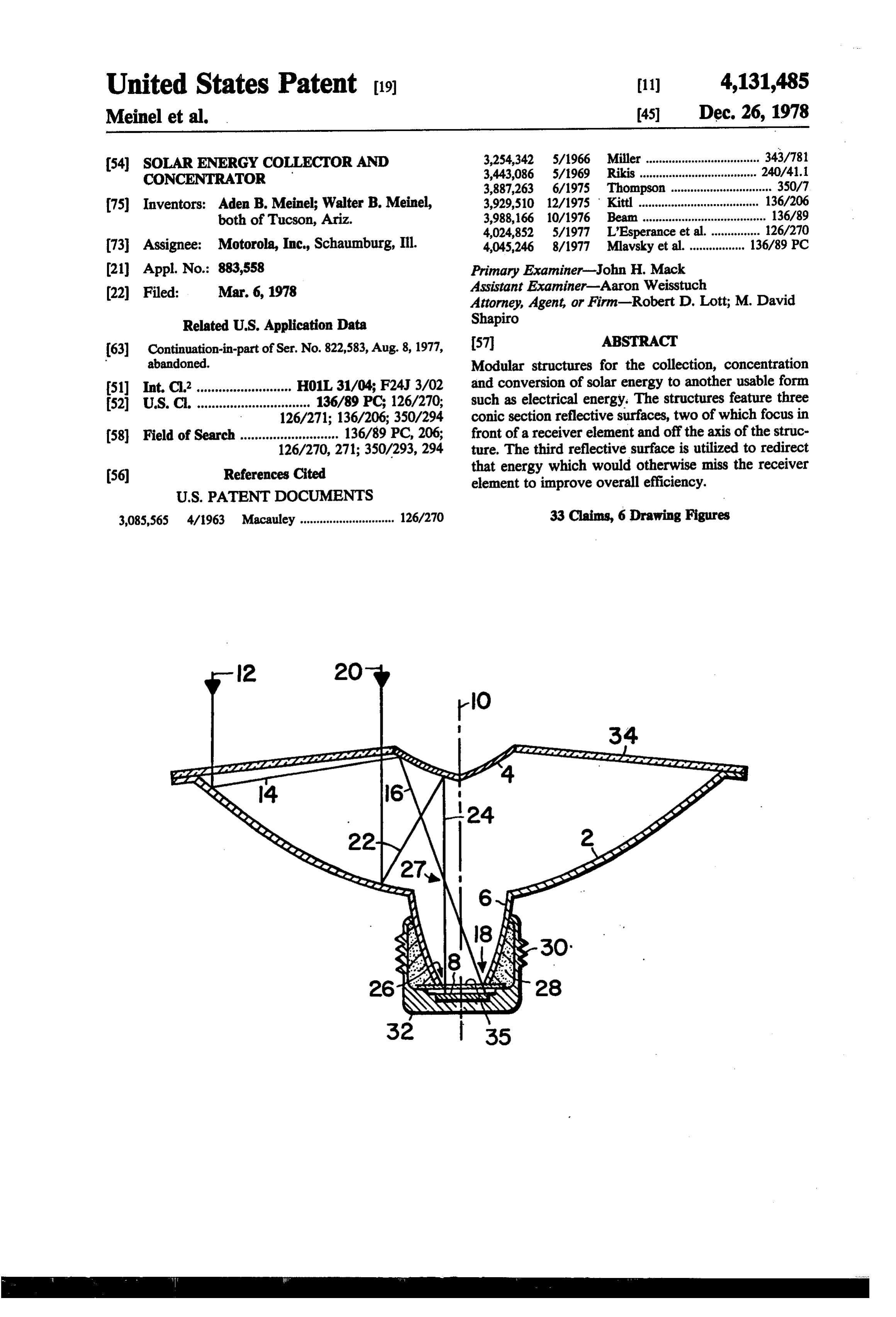
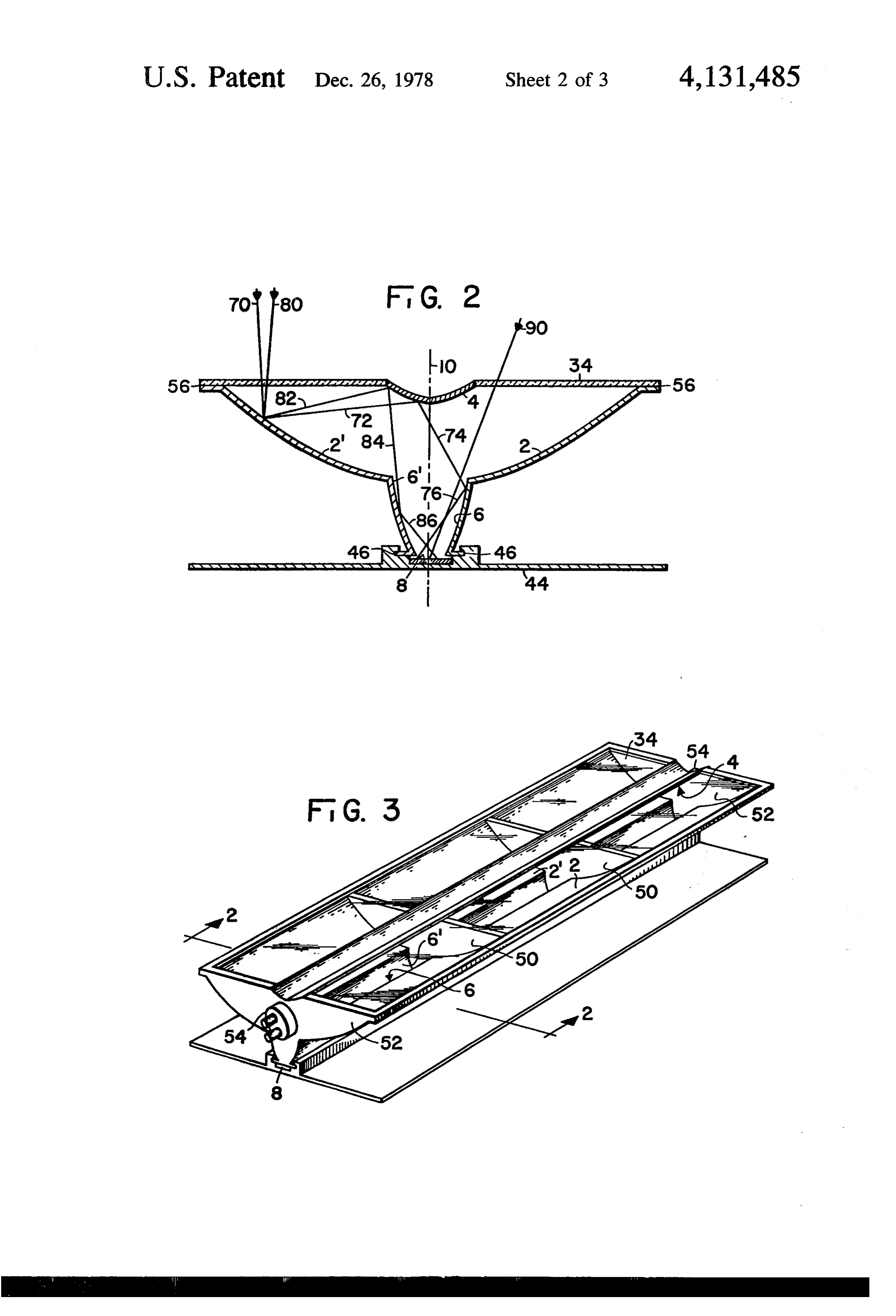
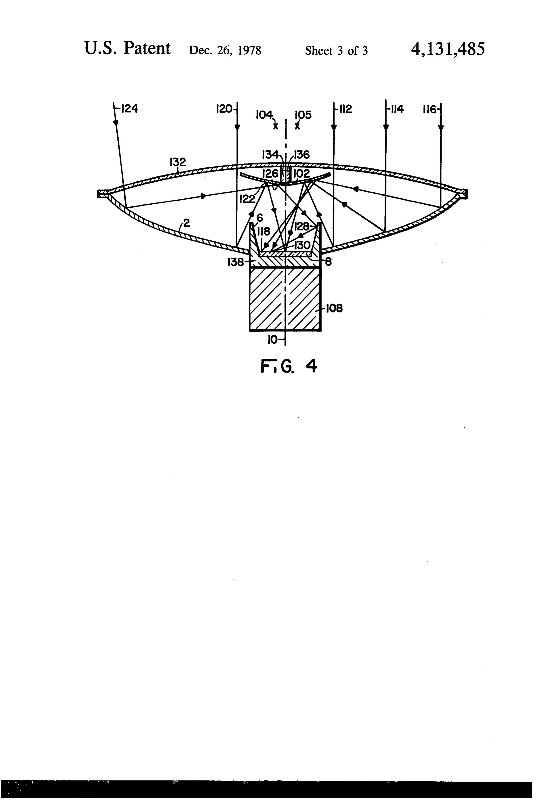
FIG. 2 is a cross may be of another embodiment of developed by sweeping the higher level of energy over a smaller area, and (2) that 25 axis of the cross section through a plane. the structure be able to accept energy from the solar FIG. 3 is a three dimensional view of the embodiment source in spite of diurnal and seasonal changes in the which is developed from the cross section of FIG. 2. relative positions of source and collector. He also points out that the two requirements are generally in conflict, theFIG. 4 is a cross section of another embodiment of invention which may be developed either by rotat one with the other, in that the more effective the energy 30 ing the cross section about its axis or by sweeping the concentration is, the more difficult the tracking prob axis of the cross section through a plane. lem becomes. Levi-Setti points out that as the accep tance angle of the optical structure decreases (which is DETALED DESCRIPTION OF THE generally accompanied by an increased concentration INVENTION factor), the time during which effective concentration 35 A cross section of one embodiment of the invention is will occur during a given day becomes shorter and shown in FIG. 1. This embodiment of the invention is more tracking is required for an effective system, or, as developed by rotating the cross section of FIG. 1 on the concentration factor increases, there is a necessity axis 10 thereby creating a generally circular module. generated for more diversely directed collectors oper The optics of FIG. 1 may be better understood by fol ated in concert. In the latter case, much of the collector lowing the detailed description of energy rays as shown capacity goes unused during the available daylight per in FIG. 1. Rays 12 and 20 represent input light energy iod because of lack of illumination at the output aper parallel to axis. 10 from a remote electromagnetic en tures of the majority of the units. This means that the ergy source which may be the solar source. Ray 12 utilization of capital investment is relatively poor in enters the system through transparent portion 34 and is those systems which depend upon multiple collectors in 45 reflected from primary reflector 2 as ray 14. Ray 14 is lieu of a single unit plus tracking mechanisms unless directed to secondary reflector surface 4 and is reflected there exists a good tradeoff between the cost of the as ray 16. Ray 16 passes through transparent sealing extra collectors and the cost of the tracking mechanism plate 35 (if used) and impinges upon receiving element for a single unit. 8 at point 18. Ray 20 also enters the system through 50 transparent portion 34 and is reflected from primary
SUMMARY OF THE INVENTION
reflector 2 as ray-22. Ray 22 is directed to secondary
According to the present invention, a non-imaging reflector 4 and is reflected as ray 24. Ray 24 passes modular optical system is utilized to collect and concen through transparent sealing plate 35 (if used) and im trate solar energy. The system employs two reflective pinges upon receiving element 8 at point 26. It will be surfaces with a nominal ray crossover point in front of 55 clear that any ray entering transparent element 34 be the receiving element which distributes the available tween rays 12 and 20 will also be reflected in order from energy uniformly across the receiving element to avoid reflective surfaces 2 and 4 and impinge on receiving hot spot problems. The system also is provided with a element 8 between points 18 and 26. Rays of this sort are third reflective surface which serves to direct stray omitted from the illustration of FIG. 1 for clarity. It is energy to the receiving element whether the stray en 60 important to note that rays 16 and 24 cross at point 27. ergy be the result of low quality reflective surfaces or This point lies between reflector surface 4 and receiving less than perfect tracking of the system with respect to element 8. The system is arranged so that all rays which the energy source. lie parallel to and between rays 12 and 20 will also cross Therefore, according to one aspect of the invention, approximately at point 27. Thus point 27 becomes the uniform illumination of the receiving element is accom 65 nominal ray crossover point for the folded optical sys plished by the use of an off axis conical second reflector tem comprising reflective elements 2 and 4. When the with a nominal ray crossover point short of the receiv cross section of FIG. 1 is rotated around axis 10 it be ing element. comes clear that point 27 is also rotated therearound
Page 6
and, thus, crossover point 27 defines a crossover ring. percent of the energy input which is lost must be dissi This crossover ring is, by design, located between re pated to avoid overheating receiving element 8. A heat flective surface 4 and receiving element 8. Since ray 12, sinking arrangement is therefore provided. Shell32 (see 14 and 16 and ray 20, 22 and 24 represent extremes of FIG. 1) extends around receiving element 8 and around the input rays along a radius of the system, it is clear 5 reflector surface 6 and is provided with threads 30. Heat that all rays in that radius are arranged to be distributed conducting material 28 is provided between reflective across receiving element 8 between points 18 and 26. It surface 6 and shell32. Photovoltaic cell 8 is soldered or then may be further seen that input rays along any other otherwise attached to shell32. This arrangement allows radius of the system will be distributed completely shell 32 to be screwed into a receptacle, similar to an across the diameter of receiving element 8. However, it O electric light bulb receptacle (not shown) for mounting should be noted that none of the other input rays are of the module of FIG. 1. This provides good heat con shown in FIG. 1 for purposes of clarity. duction from receiver element 8 into the receptacle (not All input rays to the system do not enter in a manner shown) thereby removing excessive heat from receiver such as rays 12 and 20 nor are all rays even parallel to element 8.
rays 12 and 20. Because there may be energy input 15 In the fabrication of the embodiment of the invention along other lines due to tracking errors such as is shown as shown in FIG. 1 it would be expected that reflective by rays 70, 80 and 90 in FIG. 2 (omitted from FIG. 1 for surface 4 and transparent element 34 might be fabri clarity), a third reflector 6 is introduced into the system cated from one piece of material. The material might be between the aperture in reflector 2 and receiving ele either glass or plastic with transparent section 34 as ment 8. As further shown by FIG. 2, by example, rays 20 shown and preferably with the reflective surface on the 70 and 80 are reflected by reflective surfaces 2 and are inner side of reflective portion 4. Reflective surfaces 2 directed as rays 72 and 82 to reflective surface 4 and and 6 may also be fabricated from a single piece of then as rays 74 and 84 to reflecting surface 6 and then as material, for example glass, plastic or metal. Here again, rays 76 and 86 to receiver element 8. Rays 70 and 80 it is preferable to render the inside surfce reflective in represent approximately the angular limits of acceptable 25 order to avoid losses in the material. When carefully rays due to tracking errors or inaccuracies. Similarly, sealed joints are made between transparent surface 34 other rays which would otherwise miss element 8 be and reflector surface 2 and between reflective surface 6 cause of fabrication or module alignment inaccuracies and receiving element 8 or transparent plate 35, the will be reflected by surface 6 to receiver element 8. Of module of FIG. becomes a sealed unit which is less course, ray 90 (and like rays) of FIG. 2 impinges ele subject to contamination by dirt, at least on the interior ment 8 directly without being reflected from any of the surfaces. Maintenance of such a sealed module becomes reflective surfaces of the module. a simple matter of keeping transparent surface 34 clean. A diffuser plate (not shown) may be placed within the Heat transfer material 28 between reflective surface 6 cavity of the third reflective surface 6 in order to diffuse and shell 32 may be a mixture of plastic and metal, or the light as it passes toward receiver element 8 thereby 35 where reflective surface 6 is made of metal the heat making a more uniform light distribution over receiver transfer material 28 may take the form of solid metal, element 8. Such a diffusion element is not shown in possibly even cast as a portion of reflective surface 6. FIG. 1 in the interest of clarity of the drawing. Also, This sort of fabrication lends itself to the feasibility of third reflector surface 6 may be either a smooth, contin rolling shell 32 around heat transfer material 28 at the uous surface or a bumpy, textured reflective surface. It open end of shell 32. Of course other techniques will should be noted that the uniform distribution of rays occur to one skilled in the art which would be equally from one radius of the system across receiver 8 does not satisfactory.
assure a uniform brightness (i.e. energy) distribution on Reflective surfaces 2, 4 and 6 are illustrated in F.G. 1 receiver 8 from the entire aperture of the module. For as smooth conical section surfaces. Reflective surface 6 example, if the cross section of FIG. 1 is rotated around 45 may be either a smooth continuous surface or textured center axis 10 to form a circular module, then a uniform reflective surface. Any of the reflective surfaces may be distribution of the rays from one radius of the system alternately divided into discrete elements as is typified across receiver 8 would not produce a uniform bright by Fresnel mirrors. Reflective surface 2 should prefera ness or energy distribution on receiver 8. This is due to bly take an approximately parabolic shape with an axis the masking of the center portion of the primary re 50 coincident or substantially coincident with axis 10 of the ceiver produced by the shadow of the secondary re module. Surface 4 is preferably approximately hyper ceiver and the necessary extension of the rays striking bolic with an axis slightly tilted from axis 10 of the the primary receiver to compensate for the shaded area. module. FIG. A further illustrates the development of Those skilled in the art will understand that the control the shape and position of reflective surface 4. Hyper of the brightness and energy distribution on surface 8 is 55 bola 5 has axis 11 which is tilted through angle e and further accomplished by allowing surfaces 2 and 4 to can be offset from axis 10 of the module of FIG. 1. depart from true conic sections as may be desired. Reflective surface 4 is one segment of hyperbola 5. It is Reflective surfaces 2, 4 and 6 may be either on the the slight tilting of axis 11 of the hyperbola of surface 4 inside or the outside of the module of FIG. 1, but for which cause the nominal ray crossover point to be off reasons which will become apparent, it is preferable to 60 axis 10 of the module. Further, the hyperbolic section put the reflective surfaces on the inside. selected is so selected as to provide for a nominal ray Receiver element 8 may be a photovoltaic cell or crossover point which is short of the distance from other light absorbing device. It will preferably have a reflective surface 4 to receiver element 8. This is clearly diameter similar to the lower aperture in reflector ele shown at point 27 in FIG. 1. Reflective surface 6 of ment 6. Since at the time of the making of this invention 65 FIG. 1 is preferably approximately an elliptic section photovoltaic cells of the type which would be expected with the axis of the ellipse being at an angle cb with to be employed in the invention have a maximum effi respect to axis 10 of the module. FIG. Billustrates this ciency of about 20 percent, it is apparent that the 80 in more detail. The ellipse 7 has axis 13 set at angled
Page 7
from module axis 10. Reflective surface 6 is a portion of described. For this reason parallel entry rays from the ellipse 7. The axis of ellipse 7 can be parallel and coinci solar source are not shown. The cross section of FIG.2 dent with axis 10, but capability to redirect rays to re does vary from that of FIG. 1. A formed foot at the ceiver 8 is improved if axis 7 of the third conic is in lower end of reflective surface 6 is engaged in a slot clined as shown in FIG. 1B In practice, small deviations 5 formed in heat dissipating plate 44 at point 46. In FIG. between coincidence of axis 10 with the axis of reflector 2 receiving element 8 appears to be the same as in the surface 2 or deviation of reflector surface 4 from its cross-sectional view of receiving element 8 in FIG. 1, optimum position will cause some of the rays from but it should be clearly understood that in FIG. 3 re reflector surface 4 to miss receiving element 8. As has ceiver element 8 is actually of a ribbon form. That is, been previously discussed, this situation is corrected by 10 receiver element 8 extends the full length of the module the presence of reflector surface 6 which redirects such of FIG. 3. As in the embodiment of the invention illus stray rays back to receiver element 8. Therefore, it may trated in FIG. 1, the three linear reflecting surfaces can be seen that small errors caused by inaccuracies in fabri be combined into an integral module thereby providing cation of the module of FIG. 1 are corrected by the protection of the reflecting surfaces from environmen presence of reflector surface 6. Similarly, if rays 12 and 15 tal degradation. Also, as in FIG. 1, the configuration of 20 and the like do not enter the module of FIG. 1 paral FIGS. 2 and 3 has an acceptance angle for sunlight that lel to axis 10 some of them also miss receiver element 8, permits generous manufacturing errors in the optical absent the presence of reflector surface 6. However, surfaces or errors in pointing of the module toward the reflector surface 6 does allow for inaccuracies in point Sun, an important pair of characteristics when the prac ing of the module of FIG. 1 such that all of the entry 20 tical and economic aspects of the solar collectors are rays such as rays 12 and 20 will eventually be reflected considered.
to receiver element 8 even when they are influenced by The basic optical configuration in both embodiments inaccuracies in the pointing or tracking of the module of consists of three linear reflecting surfaces, the first two FIG. 1 with respect to the solar source. forming a low quality image of the source and the third All of the reflective surfaces described above are 25 acting to bring rays that would otherwise miss the re circularly symmetrical about the axis of rotation 10, ceiver back to the receiver. When these three reflective which is not necessarily the optical axis of either para surfaces are made an integral part of the structure of the module, a fourth optical part, a transparent window, bolic surface 2, hyperbolic surface 4 or elliptical surface becomes 6 described above. Requirement that departures from part of the optical module. The function of the coincidence of the optical axis of the module with the 30 optical modules is the same however with or without axis of symmetry 10 be small is set by the functional the window. In the configuration of FIGS. 2 and 3 the requirement that the spot of concentrated sunlight on final strip of sunlight on the receiver element is not the receiver is uniform over the lateral extent of the what is termed a focus of the optical module since the receiver and that this energy from each side of the opti nominal focus lies well within the optical module; there cal configuration overlap on the receiver in the embodi 35 ingfore this collector can also be described as a non-imag ment of FIG. 1 and FIG. 2. optical system. However, in the case of the configu In a normal Cassegrain configuration, ray 14, after ration of FIGS. 2 and 3 the module is one having a plane reflection by the hyperbolic mirror 4, would procede to of symmetry rather than an axis of symmetry. When the the intersection of axis 10 with receiver 8. But a tilt is optical module and the module structure are combined introduced into surface 4 so that ray 16 actually im the enclosure would be made of a transparent material like glass or plastic for the portion having a window pinges on receiver 8 near its edge at point 18. The rela through tive positions of reflective surfaces 4 and 2 are impor which sunlight enters the module. Portions tant; they are positioned so that they form a modified where the sunlight does not need to pass can be made of Cassegrain configuration having its focus at point 27. any material that can provide the highly reflective sur The combination of the curvatures for mirrors 2 and 4 is 45 faces needed for the mirror portions. While there area such that the nominal ray crossover point 27 lies be wide variety of ways in which the optical module can tween reflective surface 4 and receiver element 8, al be attached to a using system the embodiment of FIGS. lowing considerable latitude in the choices of the para 2Then, and 3 illustrate the use of flanges in slots at points 46. of course, the module of FIGS. 2 and 3 can func bolic and hyperbolic curves.
It will be well understood that where the module of 50 tion properly with receiver 8 external to the module or FIG. 1 is sealed to prevent breathing in the space within contained in or as part of the module. As in the embodi the optical module, the walls in the module must be surfaces ment of FIG. 1, this embodiment may utilize reflector rigid enough to withstand variation of internal pressure faces which which are either single, smooth curves or sur are divided into discrete elements as is due to heating of the module or fluctuations in ambient 55 typified by Fresnel air pressure and/or temperature. A transparent glass or mirrors. Since in either embodiment plastic cover may be introduced to improve the seal at of the invention, or for that matter, in any other collect the exit aperture of reflector surface 6. This is shown in ing and concentrating system involving photovoltaic FIG. 1 by the presence of optional glass plate 35 be cells, such as receiver element 8 may be, there is gener ally a requirement for some way of dissipating the heat tween the exit aperture of reflector 6 and receiver ele 60 generated ment 8. by the surplus adsorbed sunlight energy. The A second embodiment of the invention is shown in optical module may be filled with a liquid or transparent FIGS. 2 and 3. FIG. 3 illustrates a three dimensional solid that distributes the heat to the entire shell of the view of this embodiment of the invention while FIG. 2 module through natural convection or conduction of the fluid. In the presence of such a filler the optical is a typical cross section of FIG. 3. The structure of 65 behavior
FIG. 3 is developed from the cross section of FIG. 2 by larly the of the module is only slightly affected, particu refraction of the solar rays entering the mod sweeping axis 10 of FIG. 2 through a plane. The optical ule. The descriptions given here, however, are adequate arrangement of the cross section of FIG. 2 is substan to describe the optical characteristics of the module tially the same as that of FIG. 1 which has already been
Page 8
with or without a liquid or solid filling. FIG. 2 illus sweeping the cross section through a plane. The optical trates a cross section of a linear optical module, such as arrangement of the cross section of FIG. 4 is similar to is shown in the three dimensional view of FIG. 3, with that of FIGS. 1 and 2. A primary reflective surface 2 an axis of lateral symmetry 10. The module consists of receives radiation from an electromagnetic source such three parts, the upper portion comprising window 34 5 as the sun and reflects the energy onto second reflector and reflector 4, and two identical lower portions com 102, which in turn reflects the radiant energy onto re prising reflective elements 2 and 2' and reflective ele ceiver element 8. The general shape of primary reflec ments 6 and 6. These lower portions are connected to tor 2 is substantially the same as that for FIGS. 1 and 2 the upper portion and preferably sealed at connecting in that it is a conical concave reflector having a center points 56. The lower portions of reflectors 2,2' and 6,6' 10 aperture for holding a receiving element 8 contained are provided with flanges which fit into slots in the heat within third reflector element 6. Third reflector element plate sink 44 at points 46. As before stated, the optical 6 is similar to reflector element 6 of FIGS. 1 and 2 in description of the module may be understood by fol that it is generally a concave conical section having its lowing the solar rays as shown in FIG. 1 since the opti axis off center axis 10 of the cross section of FIG. 4. cal cross sections of FIGS. 1 and 2 are essentially identi 15 However, the embodiment of FIG. 4 departs from cal. But since the configuration of FIG. 3 is developed that of FIG. 1 and FIG. 2. Receiving element 8, which by moving axis 10 of FIG. 2 through a plane, point 27 in is set on a line below the curvature plane of primary the optical diagram of FIG. 1 no longer represents a reflector 2 of FIGS. 1 and 2, is now substantially tan circle or ring. Rather, since point 27 is moved in a gential to primary reflector 2 of FIG. 4 to thereby pro straight line parallel to the motion of axis 10 in the 20 vide a shallower apparatus than that shown in the previ plane, and since the ray diagram is symmetrical about ous embodiments. This shallow configuration results in axis 10, the nominal ray crossover point is represented part from the modified distribution of rays on receiving by two lines, one on either side of axis 10. But again, as element 8. The incoming rays falling on the right hand in FIG. 1, the rays diverge from point 27 to the points side of axis 10 are evenly distributed only on the left where they impinge on receiver element 8 and the result 25 hand side of receiver element 8. Similarly, those incom is that a row of rays inputting the system along a line ing rays falling on the left hand side of axis 10 of the perpendicular to axis 10 will completely cover receiver apparatus are directed towards the right hand side of element 8, as reflected thereon, in dual fashion. That is, receiving element 8. This right-to-left-hand and left-to the overlap of rays from one side of axis 10 completely right-hand transfer of the incoming rays allows receiv overlap those rays which eminate from the opposite 30 ing element 8 to be brought up into a position substan side of axis 10. Input energy ray lines which enter the tially trangential to primary reflector 2. The paths of system at an angle with respect to axis 10 will include these rays are discussed in more detail below. The em some rays which, absent reflective surfaces 6 and 6', bodiment of FIG. 4 is also similar to FIG. 1 and FIG. 2 would not impinge on receiver element 8. As has been in that heat sinking element 108 is attached to reflecting before stated, rays 70 and 80 of FIG. 2 represent rays 35 surface 6 to provide heat transfer from receiving ele which illustrate this case. However, in the presence of ment 8 to thereby prevent overheating of element 8. reflector 6 rays 70, 80 are redirected by reflector 6 to The embodiment shown in FIG. 4 indicates air-cooled receiver element 8. fin 108, however it will be understood that either of the FIG. 3 which may be developed from FIG. 2 by threaded base of FIG. 1 or the flanged foot of FIG. 2 or moving axis 10 through a plane illustrates some addi any other heat sinking means could also be used as a tional elements of this embodiment of the invention. heat sink for receiver 8.
End plates 52 serve to help isolate the volume of the Turning to the rays depicted in FIG. 4, incoming rays collector module of FIG. 3 from the exterior environ 112, 114, and 116 impinging on the right hand side of ment. Transparent partitions 50 are shown along the primary reflector 2 are reflected onto the right hand length of the optical module to stiffen the surfaces of the 45 side of secondary reflector 102 and subsequently re module and thereby reduce optical deformations that flected onto receiving element 8 such that incoming ray might otherwise occur. Transparent partitions 50 may 112 which is closest to center axis 10 is reflected to also be opaque, but reflective, so as not to cause the loss center axis 10 of receiving element 8. Conversely, in of obliquely incident sunlight. End plates 52 may be coming ray 116 which is farthest from axis 10 impinges transparent or reflective so as not to cause the loss of 50 on receiving element 8 on the far left hand side shown obliquely incident sunlight. Because of the relatively at point 118. Analogously incoming ray 120, which just larger volume of the module of FIG. 3, heat sink plate misses secondary reflector 102, impinges on receiving 44 is attached but not sealed to the optical module so element 8 at center axis 10 after being reflected from that air pressure changes will result in a slow exchange secondary reflector 102 at point 122. Thus, it can be of air in the module. Of course, it will be understood 55 seen that the rays entering on the right hand side of the that if the unit were to be completely sealed, a bellows axis 10 impinge on receiving element 8 to the left of or other type of expansion chamber might be used to center axis 10, and those entering on the left of axis 10 compensate for temperature and pressure changes. End impinge on receiving element 8 on the right hand side of plates 52 are shown with connector sockets 54 installed. axis 10. Incoming ray 124 indicates the use of third Connector sockets 54 may be used for physically attach 60 reflector 6 for conditions where the apparatus is not ing the module to a using structure and also, optionally, pointing directly at the electromagnetic radiation for electrical connections between receiver elemen 8 source. Incoming ray 124 is reflected off secondary and the using structure. reflector 102 at point 126 striking third reflector 6 at FIG. 4 is a cross section of another embodiment of point 128 and is further reflected onto receiving element the invention. This embodiment may be realized as a 65 8 at point 130. This operation is the same as for off axis generally circular module by sweeping the cross section rays 70, 80, 90, discussed in conjunction with FIG. 2. around axis 10 or may be realized as a generally trough Thus the configuration of FIG. 4 has an acceptance shaped module similar to that depicted in FIG. 3 by angle for sunlight that permits generous manufacturing
Page 9
errors in the optical surfaces or errors in pointing of the of a conic section, said first conic section shape module toward the sun. having an axis substantially coincident with the axis It will be appreciated by those skilled in the art that of the apparatus, said first reflective means having the curvature of the primary reflector and the second an aperture around said apparatus axis; ary reflector are a matter of choice as long as they 5 second reflective means spaced from said first reflec produce in combination the desired placement of the tive means for collecting said energy reflected incoming rays onto receiver element 8. A convenient from said first reflective means and for further curvature for second reflector 102 of FIG. 4 is two reflecting the energy through said aperture in said sections of a circle with the center of both circles being first reflective means, that portion of said second off axis 10 of the cross section. Thus, in FIG.4, the right 10 reflective means lying on one side of the axis of the hand portion of reflector 102 has a center locus at 104, apparatus and facing said first reflective means and the left hand portion has a locus at 105. The curva being convex and having a shape generally of a ture of primary reflector 2 has approximately a para conic section, said second conic section shape hav bolic shape, the exact dimensions of which are derived ing an axis being angularly displaced from the axis by standard techniques of the art. 15 of the apparatus; and
The cross section of FIG. 4 also differs from the cross receiving means for absorbing said further reflected sections of FIGS. 1 and 2 in that secondary reflector energy, a nominal ray crossover point of said fur 102 is not an integral part of transparent dome 34 of ther reflected energy being between said second FIGS. 1 and 2 but rather is supported from transparent reflective means and said receiving means, said dome 132 of FIG. 4 by supporting rod 134. Supporting 20 receiving means being positioned to receive said rod 134 also contains an insulating collar 136 which further reflected energy through said aperture in helps to prevent the heat generated on the second re said first reflective means, said further reflected flective surface by the reflected sunlight from overheat energy being thereby dispersed generally over said ing the dome, which in some instances may be plastic, thus deforming transparent dome 132. Collar 136 can 25 2. receiving The means.
apparatus according to claim 1 wherein:
also be shimmed in an appropriate manner to provide a third reflective means for reflecting electromag fine positioning a secondary reflective surface 102. Note netic radiation energy is connected between said that it would also be possible to support second reflec first reflective means at said aperture and a perime tive surface 102 by supporting bars mounted from sec ter of said receiving means, said third reflective ond reflector 102 to shell 138 which supports reflector 30 means having a shape generally of a conic section.
6 and extends around receiving element 8. This configu 3. The apparatus according to claim 2 wherein the ration would have the added advantage that deforma apparatus tions in the reflective surfaces due to heating and cool about the isaxis further defined by rotating the cross section of the apparatus to develop a structure ing of the surfaces would not change the relative dis having circular cross sections. tance from the first reflective surface to the second 35 reflective surface. 4. The apparatus according to claim 3 wherein: said third reflective means is enclosed and connected
Except for the differences noted, the embodiment of to a shell, said shell having on the outer surface FIG. 4 has substantially the same characteristics and the thereof connecting means for connecting the appa same possible variations described for FIGS. 1 and 2.
For instance, the surfaces may be smooth or may be 40 5. ratus The to a using structure.
apparatus according to claim 4 wherein said made up of a plurality of fresnel mirrors and a diffuser plate may be placed over the receiving unit to aid in shell comprises a heat sink.
6. The apparatus according to claim 3 comprising:
providing even energy distribution along receiving unit transparent means for supporting said second reflec Finally, it is also possible to place onto reflective 45 tive means and for allowing transmission of elec surface 6 of FIGS. 1, 2 or 4 light sensing means which tromagnetic energy therethrough, said transparent would detect a module which is not pointing directly means having an outer perimeter, said outer perim into the sun. A correct positioning of the apparatus will eter being coextensive with an outer perimeter of result in equal amounts of light shining on both sides of said first reflective means. reflective surface 6, but an error in alignment will cause 50 7. The apparatus according to claim 2 wherein the one side of the reflective surface 6 to be brighter than apparatus is further defined by moving the axis of the the opposite side. Thus, using differential means, it apparatus in a plane to develop a trough-like structure would be possible to detect aligning errors in the appa of8.modular The form.
apparatus
according to claim 7 wherein:
ratus.
Various other modifications and changes may be 55 heat sink means for dissipating excess energy from made to the present invention from the principles of the said receiving means is connected to said receiving invention as described above without departing from 9. The
apparatus according to claim 7 comprising the spirit and scope thereofas encompassed in the ac transparent means for supporting said second reflec companying claims.
What is claimed is: 60 tive means and for allowing transmission of elec 1. An apparatus for collecting energy from a remote tromagnetic energy therethrough, said first reflec electromagnetic radiation source, the apparatus having tive means and said transparent means having outer a cross section generally symmetrical about an axis, a extremities thereof, said outer extremities of said cross section of the apparatus comprising in combina first reflective means and said transparent means tion: 65 being coextensive.
first reflective means for collecting and reflecting the 10. The apparatus according to claim 2 wherein said conic section of said third reflective means is angularly energy from the remote source, said first reflective displaced means being concave and having a shape generally from the axis of the apparatus.
Page 10
11. The apparatus according to claim 1 wherein said heat sink means for dissipating excess energy from receiving means comprises a photovoltaic cell. said receiving means is connected to said receiving 12. An apparatus for collecting energy from a remote 182S.
electromagnetic radiation source, the apparatus having 20. The apparatus according to claim 18 comprising: a cross section generally symmetrically about an axis, a transparent means for supporting said second reflec cross section of the apparatus comprising in combina tive means and for allowing transmission of elec tion: tromagnetic energy therethrough, said first reflec first reflective means for collecting and reflecting the tive means and said transparent means having outer energy from the remote source, said first reflective 10 extremities thereof, said outer extremities of said means being concave and having a shape generally first reflective means and said transparent means of a conic section, said first conic section shape being coextensive.
having an axis substantially coincident with the axis 21. The apparatus according to claim 13 wherein said of the apparatus, said first reflective means having conic section of said third reflective means is angularly displaced from the axis of the apparatus.
an aperture around said apparatus axis; 22. The apparatus according to claim 12 wherein said second reflective means spaced from said first reflec 15 receiving means comprises a photovoltaic cell. tive means for collecting said energy reflected 23. An apparatus for collecting energy from a remote from said first reflective means and for further reflecting the energy through said aperture in said aelectromagnetic radiation source, the apparatus having first reflective means, that portion of said second 20 having a right side and a symmetrical cross section generally about an axis and reflective means lying on one side of the axis of the apparatus comprising in combination: section of the left side, a cross apparatus and facing said first reflective means first reflective means for collecting and reflecting the being convex and having a shape generally of a energy from the remote source, said first reflective conic section, said second conic section shape hav means being concave and having a shape generally ing an axis being angularly displaced from the axis 25 of a conic section, said first conic section shape of the apparatus, said second reflective means hav having an axis substantially coincident with the axis ing a nominal ray crossover point of said further of the apparatus, said first reflective means having reflected energy lying off the axis of the apparatus, an aperture around said apparatus axis; and second reflective means spaced from said first reflec receiving means for absorbing said further reflected 30 tive means for collecting said energy reflected energy, said receiving means comprising a receiv from said first reflective means and for further ing surface area, said nominal ray crossover point reflecting the energy through said aperture in said of said further reflected energy being between said first reflective means, that portion of said second second reflective means and said receiving means, reflective means lying on one side of the axis of the said receiving means being positioned to receive 35 apparatus and facing said first reflective means said further reflected energy through said aperture being convex and having a shape generally of a in said first reflective means, said further reflected conic section, said second conic section shape hav energy being thereby dispersed generally over said ing an axis being angularly displaced from the axis receiving means. of the apparatus; and 13. The apparatus according to claim 12 wherein: receiving means for absorbing said further reflected a third reflective means for reflecting electromag energy, said receiving means comprising a receiv netic radiation energy is connected between said ing surface area, a nominal ray crossover point of first reflective means at said aperture and a perime said further reflected energy being between said ter of said receiving means, said third reflective second reflective means and said receiving means, means having a shape generally of a conic section. 45 said receiving means being positioned to receive 14. The apparatus according to claim 13 wherein the said further reflected energy through said aperture apparatus is further defined by rotating the cross section in said first reflective means, said further reflected about the axis of the apparatus to develop a structure energy being derived from the energy of the re having circular cross sections. mote source impinging of the right side of the appa 15. The apparatus according to claim 14 wherein: ratus being thereby dispersed generally over a left said third reflective means is enclosed and connected side of said receiving means, and said further re to a shell, said shell having on the outer surface flected energy being derived from the energy of thereof connecting means for connecting the appa the remote source impinging of the left side of the ratus to a using structure. apparatus being thereby dispersed generally over a 16. The apparatus according to claim 15 wherein said 55 right side of said receiving means. shell comprises a heat sink. 24. The apparatus according to claim 23 wherein: 17. The apparatus according to claim 14 comprising: a third reflective means for reflecting electromag transparent means for supporting said second reflec netic radiation energy is connected between said tive means and for allowing transmission of elec first reflective means at said aperture and a perime tromagnetic energy therethrough, said transparent 60 ter of said receiving means, said third reflective means having an outer perimeter, said outer perim means having a shape generally of a conic section. eter being coextensive with an outer perimeter of 25. The apparatus according to claim 24 wherein the said first reflective means. apparatus is further defined by rotating the cross section 18. The apparatus according to claim 13 wherein the about the axis of the apparatus to develop a structure apparatus is further defined by moving the axis of the 65 having a circular cross section.
apparatus in a plane to develop a trough-like structure 26. The apparatus according to claim 25 wherein: of modular form. said third reflective means is enclosed and connected 19. The apparatus according to claim 18 wherein: to a shell, said shell having on the outer surface
Page 11
thereof connecting means for connecting the appa heat sink means for dissipating excess energy from said receiver means is connected to said receiver ratus to a using structure. CaS 27. The apparatus according to claim 26 wherein said 31. The apparatus according to claim 29 comprising: shell comprises a heat sink. 5 transparent means for supporting said second reflec 28. The apparatus according to claim 25 comprising: tive means and for allowing transmission of elec transparent means for supporting said second reflec tromagnetic energy therethrough, said first reflec tive means and for allowing transmission of elec tive means and said transparent means having outer tromagnetic energy therethrough, said transparent extremities thereof, said outer extremities of said means having an outer perimeter, said outer perim 10 first reflective means and said transparent means eter being coextensive with an outer perimeter of being coextensive.
said first reflective means. 32. The apparatus according to claim 24 wherein said 29. The apparatus according to claim 24 wherein the conic section of said third reflective means is angularly apparatus is further defined by moving the axis of the displaced from the axis of the apparatus. apparatus in a plane to develop a trough-like structure 15 33. The apparatus according to claim 23 wherein said of modular form. receiving means comprises a photovoltaic cell. 30. The apparatus according to claim 29 wherein:
Provenance
- Collection
- Cited prior art
- Original PDF
- patentimages.storage.googleapis.com →
- Filed
- 1978-03-06
- Pages
- 11
- Method
- pdftotext (the PDF's own text layer) + pdftoppm 300dpi page scans
- Source
- Google Patents bibliographic record
- Granted
- 1978-12-26
- Inventors
- Aden B. Meinel; Walter B. Meinel; Motorola Inc
- Transcribed from
- patentimages.storage.googleapis.com →