patent · US4280480
Solar heating plant
28 July 1981
Page 1 — bibliographic record
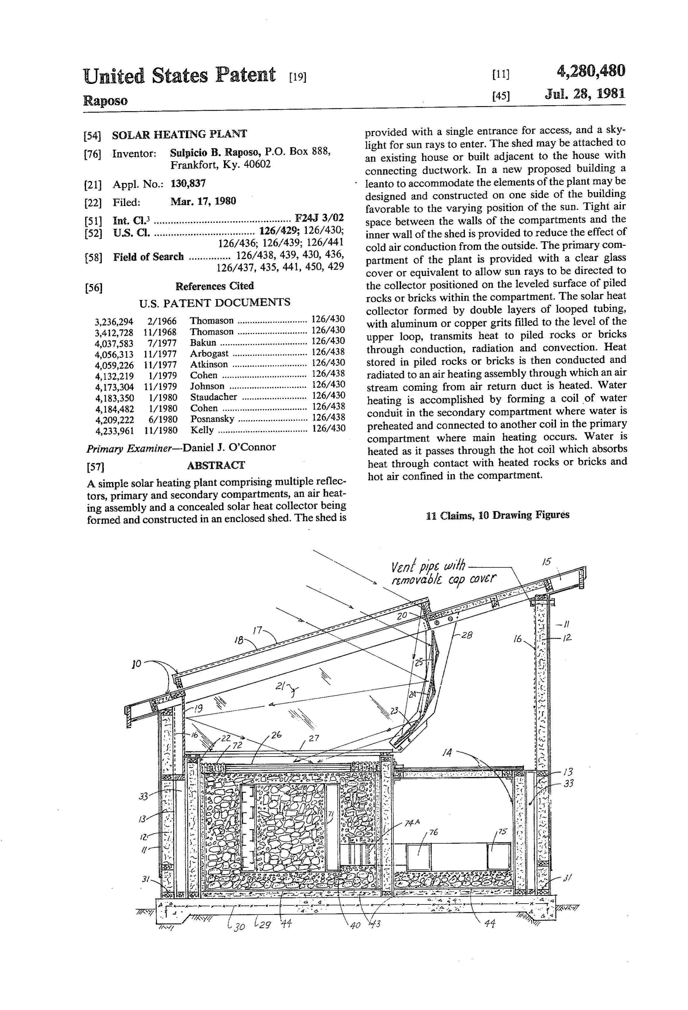
United States Paterat (19) 11) 4,280,480 Raposo 45) Jul. 28, 1981
54 SOLAR HEATING PLANT provided with a single entrance for access, and a sky light for sun rays to enter. The shed may be attached to 76 Inventor: Sulpicio B. Raposo, P.O. Box. 888, an existing house or built adjacent to the house with Frankfort, Ky. 40602 connecting ductwork. In a new proposed building a 21 Appl. No.: 130,837 leanto to accommodate the elements of the plant may be 22 Filed: Mar. 17, 1980 designed and constructed on one side of the building favorable to the varying position of the sun. Tight air 51 int. Cl.................................................. F24, 3/02 space between the walls of the compartments and the 52) U.S. C. .................................... 126/429; 126/430; inner wall of the shed is provided to reduce the effect of 126/436; 126/439; 126/441 cold air conduction from the outside. The primary com 58) Field of Search ............... 126/438,439, 430, 436, partment of the plant is provided with a clear glass 126/437, 435, 441, 450, 429 cover or equivalent to allow sun rays to be directed to (56) References Cited the collector positioned on the leveled surface of piled
collector formed by double layers of looped tubing, 3,236,294 2/1966 Thomason ............................ 126/430 with aluminum or copper grits filled to the level of the 3,412,728 E/1968 Thomason ... ... 126/430 upper loop, transmits heat to piled rocks or bricks 4,037,583 7/1977 Bakun .......... ... 126/430 through conduction, radiation and convection. Heat 4,056,313 11/1977 Arbogast ..... ... 126/438 4,059,226 1 1/1977 Atkinson .............................. 26/430 stored in piled rocks or bricks is then conducted and 4,132,219 1/1979 Cohen .................................. 26/438 radiated to an air heating assembly through which an air 4,173,304 li/1979 Johnson ............................... 26/430 stream coming from air return duct is heated. Water 4,183,350 1/1980 Staudacher . ... 126/430 heating is accomplished by forming a coil of water 4,184,482 1/1980 Cohen ......... ... 126/438 conduit in the secondary compartment where water is 4,209,222 6/1980 Posnansky ............................ 126/438 preheated and connected to another coil in the primary 4,233,961 1 1/1980 Kelly .................................... 126/430 compartment where main heating occurs. Water is
Primary Examiner-Daniel J. O'Connor heated as it passes through the hot coil which absorbs 57 ABSTRACT heat through contact with heated rocks or bricks and A simple solar heating plant comprising multiple reflec hot air confined in the compartment. tors, primary and secondary compartments, an air heat ing assembly and a concealed solar heat collector being 1 Claims, 10 Drawing Figures formed and constructed in an enclosed shed. The shed is
Page 2
Drawing sheet — no readable text.
Page 3
Drawing sheet — no readable text.
Page 4
Drawing sheet — no readable text.
Page 5
S. s '',n ra saf
SSR S. . . . . .. . . " as m 4 -
-Yv a Vu ‘. n Y S' R v T.if
sers restristors rests
WXXYSSSS
Page 6
Drawing sheet — no readable text.
Page 7
to collect and store heat at all seasons of the year as long
SOLAR HEATING PLANT as the sun shines favorably, (2) by using multiple reflec tors to increase and concentrate the amount of sun rays
BACKGROUND OF THE INVENTION directed to the heat collector, (3) by further concealing This invention relates to a simple solar heating plant the heat collector inside the primary compartment al intended for water heating and heating of residential lowing concentration of sun rays to enter the compart homes in particular, but is also applicable when modi ment through the clear glass cover, thus building heat in fied, to other type of building structures and systems the collector in shorter time and permitting escape of where hot air stream or fluid is needed. Heat collection excessive heat builtup in the collector to be conducted in this invention is effectively improved through the use O and radiated to piled rocks or bricks directly below the of multiple reflectors and a concealed solar heat collec collector, (4) by transferring additional heat to piled tor not affected by chill temperature during winter rocks or bricks by convection through the tubing coiled season. Concentration of sun rays directly received through the piled rocks or bricks through which hot from the sun and sun rays deflected through the multi fluid circulates from the collector then to the tubing ple fixed and adjustable reflectors installed within the 5 coils and back to the collector by means of pressure heat shed maximize heat buildup in the collector in shorter builtup in the collector, (5) by forming an air heating time. Heat is transmitted from the collector to piled assembly encased in piled rocks or bricks for the pur rocks or bricks stored in the primary compartment of the plant through radiation and conduction. Additional 20 pose ment of absorbing heat confined in the primary compart and for heating the air stream flowing through the heat is transmitted to piled rocks or bricks through a double coil of conduit through which hot fluid circu assembly, and finally, (6) by constructing two connect ing compartments, the walls may be formed of masonry lates from the collector to the coil and back to the col lector by means of pressure heat builtup in the collector. units, bricks, or fabricated of heavy gage sheeting or Air stream flowing through the air heating assembly of constructed of construction grade lumbers and heavy the plant is then heated and circulated to the house by a 25 gage aluininum or galvanized sheetings or the like with blower or suction fan thermostatically controlled, fiber insulation placed between horizontal and vertical which may be installed within an air duct in the crawl supporting members to minimize loss of heat through space or basement of the house. Water heating is formed the double walls of the said compartments. by coiling a water conduit in the secondary compart The aforementioned objects together with the appar ment where water is preheated and connected to an 30 ent objects and advantages as shown and illustrated other coil mounted around the inner peripheral wall of from the standpoint of the drawings and ensuing de the primary compartment where final heating occurs. scriptions thereof, provide flexibility to the present The coil obtains heat through contact with heated rocks invention in various construction techniques which may or bricks and confined hot air within the said compart comprise combination or arrangement of various parts
and elements as defined in the embodiments and claims
This invention utilizes commercially available materi appended als mostly found in hardware and lumberyard stores and herewith.
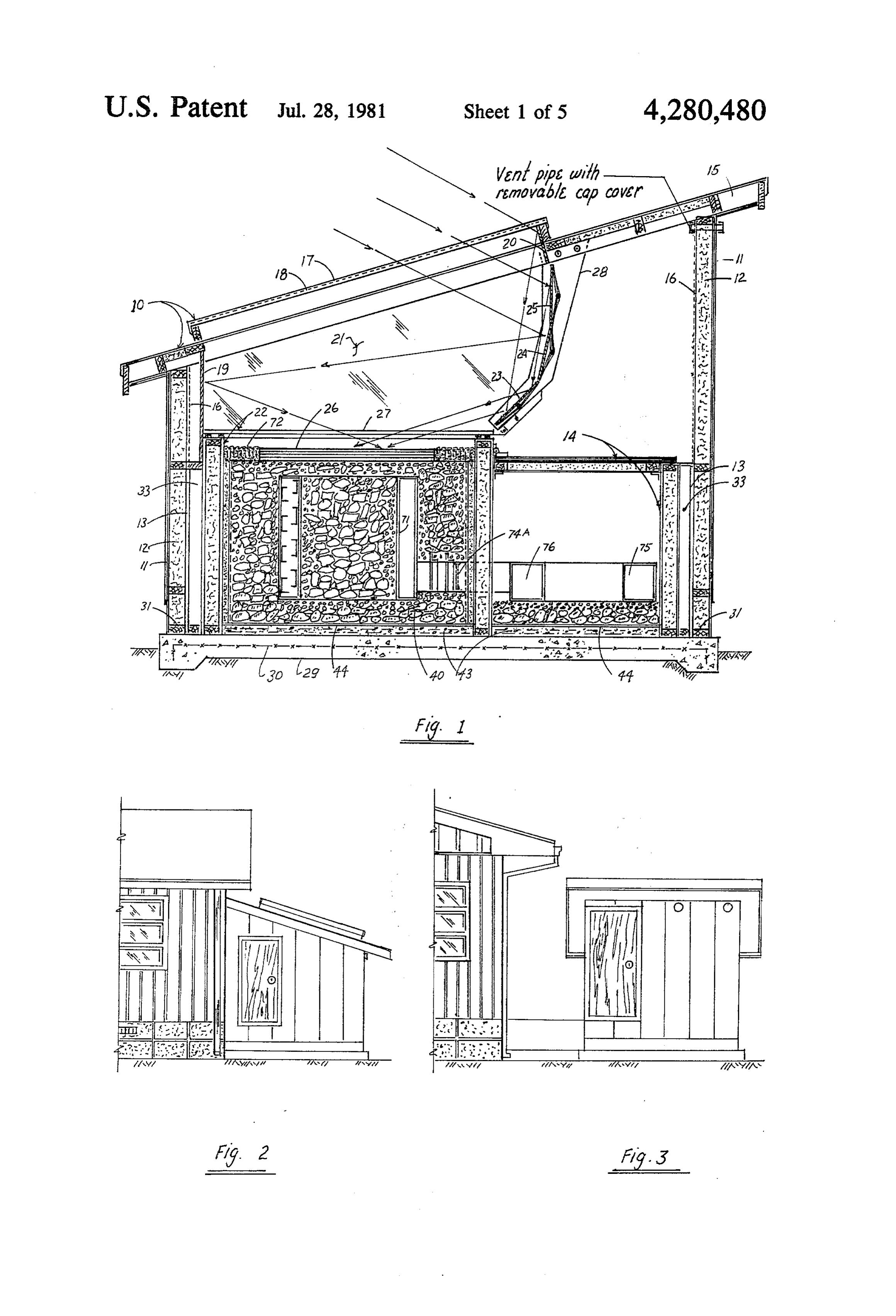
does not require any electrical gadget within the plant. DESCRIPTION OF THE DRAWINGS A simple yet effective improvement of collecting heat from the sun, even on winter season, enables the plant 40 FG. i is a sectional view showing the major ele instantly to replace used heat when the sun shines, due ments of the solar heating plant, the reflectors, the heat to the fact that the plant has multiple reflectors and collector and the air heating assembly inside the pri none of the heat collector's part is exposed to chill tem mary compartment, the air return and air supply ducts perature. in the secondary compartment and an air duct with 45 swing type shutter connecting the air heating assembly
SUMMARY OF THE INVENTION and the air return duct.
It is the prime object of the present invention to coi FIG. 2 is an elevation view of the plant attached to lect solar energy for home heating purposes in a much the side of the residential house.
simpler, yet effective way of collecting and storing heat, FIG. 3 is another view of the plant built adjacent to utilizing commonly available commercial materials and 50 the residential house showing a ductwork connecting affording those not familiar with the art, especially the the plant and the house.
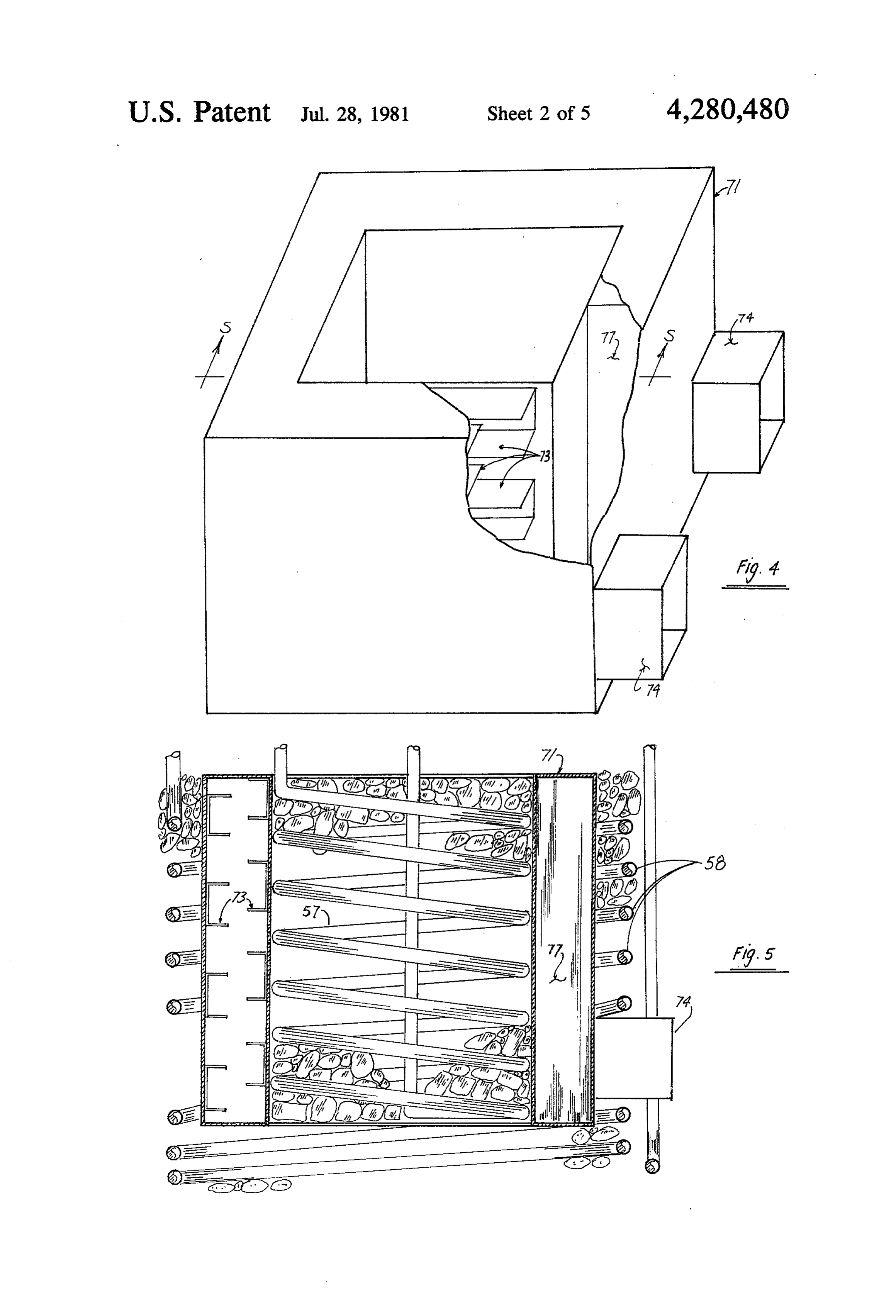
low income family, to build the invention with minimal FIG. 4 is a three dimensional view of the air heating consultation from the experts and professionals familiar assembly showing partly the U-shape bent plate inside with the construction of the present invention. the assembly and two stubbed ducts on one side to Additional objects of this invention, are (1) to collect receive connecting
ducts from air supply and air return solar energy at least from morning to afternoon sunlight ducts.
at all seasons of the year, (2) to buildup heat in the heat FIG. 5 is a sectional view along line S-S of FIG. 4 collector in shorter time, (3) to readily replace used heat showing the cross section of the U-shape bent plate in the plant's storage for a full sunshine day, (4) to use commonly available and inexpensive commercial mate 60 inside the assembly. It shows further when the assembly rials, and (5) to supplement the existing home heating is fully encased in piled rocks or bricks with double coil generator, in order to cut down considerably steadily of tubing coming from the collector, as illustrated fur rising cost of home heating. ther in FIG. 6.
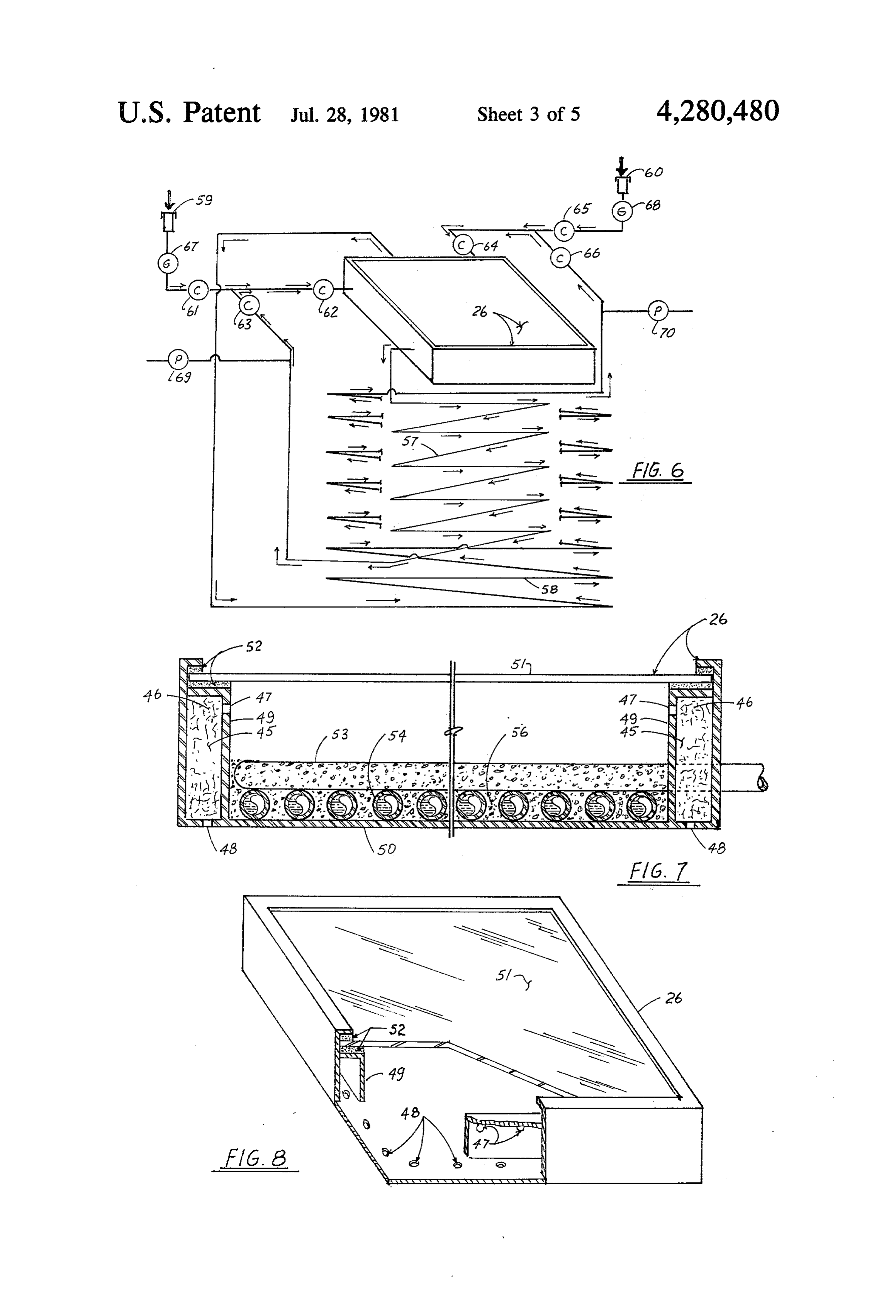
The above mentioned objectives of the present inven FIG. 6 is a schematic view of the collector and the tion are attained (1) by forming a substantially air tight 65 coil of tubing indicating the flow of the fluid from an shed to house all the components of the solar heating inlet terminal to the collector to the coil and back to the plant and to protect the heating system of the plant from collector.
chill temperature, thus making it possible for the plant FIG. 7 is a sectional view of the solar heat collector.
Page 8
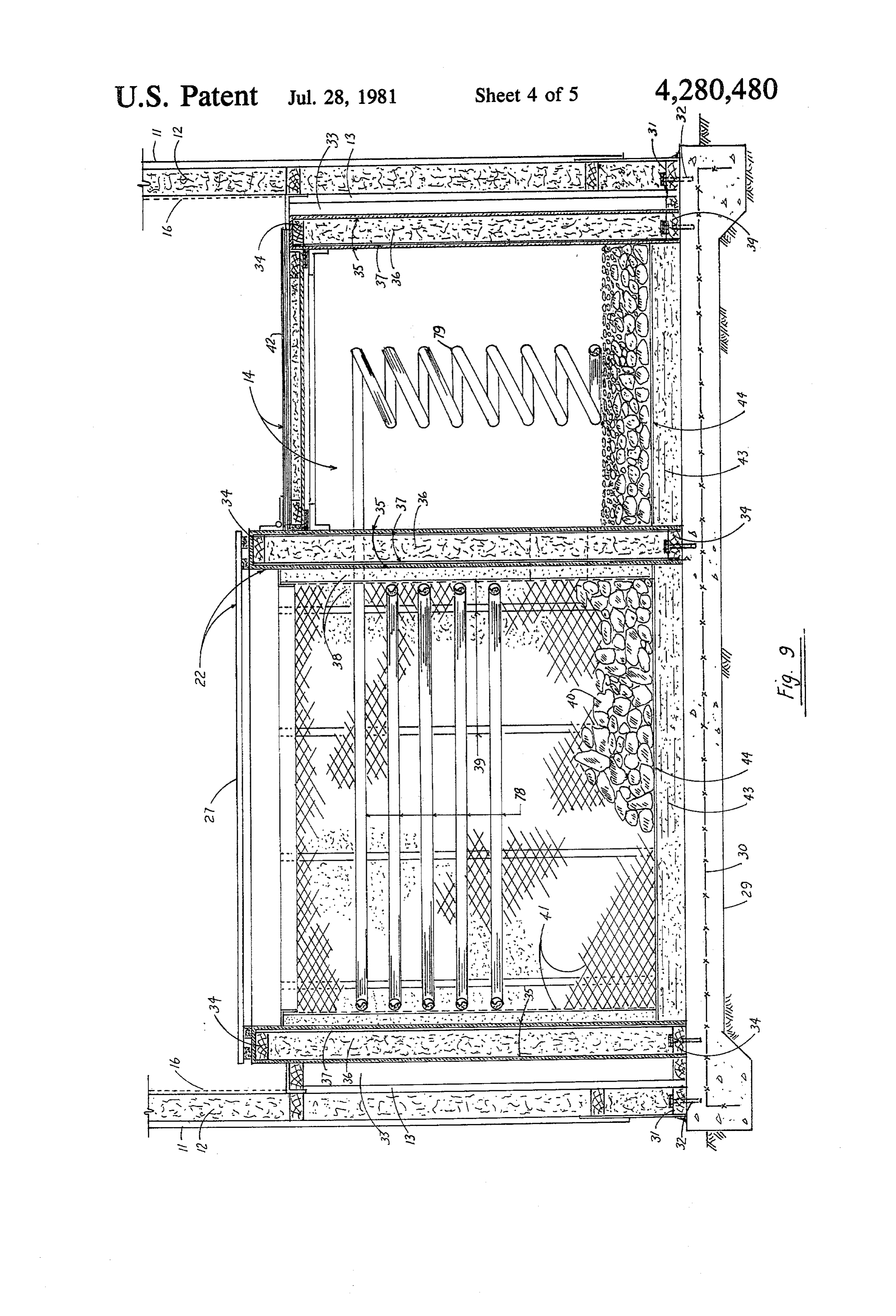
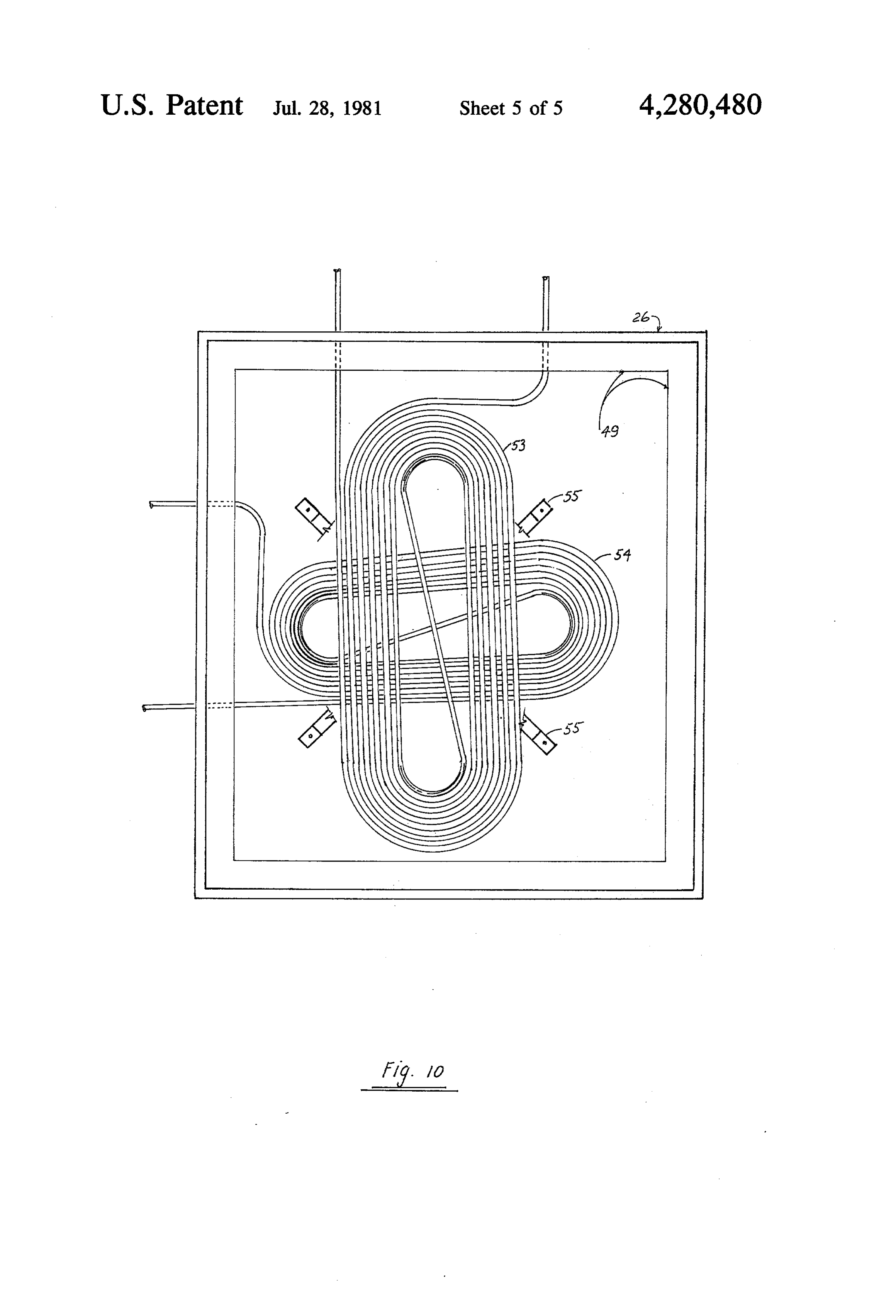
FIG. 8 is a three dimensional view of the collector partment 14 to reduce conduction of cold air coming without the double layer of looped tubing, the clear from the outside to the interior space of the primary glass cover partly cut. compartment 22 and secondary compartment 14. The FIG. 9 is an enlarged sectional view of the primary walls of the compartments as shown in FIG. 9, may be and secondary compartments, showing the coil of water constructed of bricks, masonry units, reinforced con conduit in both compartment and the major elements crete or fabricated of lightweight hollow or cellular and details of the shed and the compartment's wall. metal, but in this invention to afford the low income to FIG. 10 is a plan view of the collector showing the build one shall be formed of construction grade lumbers double layers of looped tubing starting from letter 'S' 34 and heavy gage metal 35 with fiber insulation 36, shape loop. 10 placed in spaces between vertical and horizontal mem DESCRIPTION OF THE PREFERRED bers. A strip of non-combustible layer 37 such as asbes EMBODIMENTS tos or the like, is placed between the faces of the con struction grade lumber and the heavy gage metal 35.
According to the present invention as illustrated in Referring further to FIG. 9, a blanket of fiber insulation FIG. 1, the major elements of the solar heating plant are 15 38 is laid around the outside face of the inner wall of the protected by a substantially air tight, shed 10, the walls primary compartment 22 between vertical bars 39, con may be constructed of reinforced concrete, masonry veniently spaced apart, which can be of any convenient units, bricks, plain or cellular metal or combination shaped metal bars. The blanket of fiber insulation 38 thereof, but for simplicity and economic reason are which serves to minimize loss of stored heat through preferably constructed of exterior type plywood 11, or 20 the walls of the said compartment, is protected from equivalent, and construction grade lumber framework. deforming against piled rocks or bricks 40, by netted The exterior side of the wall 11 is painted with dark wire 41, which can be a mesh wire, expanded metal, non-reflective color. Blanket of fiber insulation 12, perforated metal sheeting, or equivalent. placed between the horizontal and the vertical members The secondary compartment 4, where preheating of of the framework is enclosed by a double wall 13, may 25 the air stream and water occurs prior to entering the be a dry wall or plywood, up to the top level of the primary compartment 22, is constructed similar to that secondary compartment 14, and from there on to the of the primary compartment except that a shutter 42, is bottom side of the rafter 15, is a mesh wire or expanded provided which can be a cellular metal, double wall metal 16, indicated by broken lines. The mesh wire 16, metal sheeting or double wall plywood or combination permits the escape of heat stored in the fiber insulation 30 thereof. The space between said double wall is filled 12, at night and on cool days, to maintain warm space with porous insulation. Blanket of fiber insulation within the plant and prevent frost or light snow accu around the face of the inner wall of said compartment is mulation on the sky light 17, which may be made of optional. A layer of clay soil 43, which can be substi clear glass or any commercial clear thermoplastic sup tuted for sand or a mixture of clay and sand is placed on ported by mesh wire 18, with an opening not smaller 35 the floor of the primary and secondary compartments, than one inch square nor larger than one inch by two above which is a heavy gage metal 44, placed between inches. Four fixed reflectors 19, 20 and 21 are placed layer of clay soil 43 and piled rocks or bricks 40. The face to face on opposite sides of the primary compart clay soil 43, serves as cushion and as an insulation to ment 22, in addition to adjustable reflectors 23, 24 and provide uniform bearing pressure and minimized crack 25, which can be of ordinary glass mirror, or a highly ing effect to the concrete floor 29. reflective aluminized or plated metal, and enable the FIGS. 7, 8 and 10 show the detailed construction of plant to reflect sufficient sun rays to collector 26 placed the solar heat collector 26. The main body of the solar just below the glass cover 27, of the primary compart heat collector 26, may be fabricated of heavy gage alu ment 22. The adjustable reflectors 23, 24 and 25 may be minum sheeting, galvanized sheeting or the like, form constructed in many conventional ways. The two main 45 ing a pan with a hollow space 45, provided around the supporting panels 28, may be made of plywood, metal inside face of the pan. The space 45 is filled with a or any known suitable material, cut to a desired shape in porous insulation 46 which can be of any commercial such a way to suit the desired angle of placement of fiberglass insulation or the like. Perforated holes 47 and individual reflecting panel. The adjustable reflectors 23, 48 at the inner walls 49 and bottom plate 50 of the solar 24 and 25 are not limited to three panels as shown in 50 heat collector 26, provide escape outlets for the exces FIG. 1 of this invention, as it can be reduced to two sive heat wave builtup within the collector 26 to be panels or increased to more than three panels depending stored and retained in piled rocks or bricks 40, directly on the size of the shed 10, and pitch of its roof. The below the solar heat collector 26. Escape of hot air detail of the adjustable reflectors 23, 24 and 25 shown in wave within the solar heat collector 26 through the FIG. 1 merely exemplifies a simple view that can give 55 corners and sides of the clear glass cover 51, is inhibited an idea even to those who are not familiar with the art. by two heat resistant strips 52, which can be of asbestos The shed 10 may roofed with black shingles, but fiber or any known commercial non-combustible preferably with sheet metal painted black or dark green weather stripping. As illustrated in FIGS. 7 and 10, the or any dark non-reflective color, the underside of which double layers of looped tubing 53 and 54 are positioned is covered with fiber insulation. The foundation 29 shall 60 in such a way that one loop is over the other and the be of reinforced concrete with at least welded wire tubing secured against lateral movement by heavy gage fabric 30 as reinforcement. As indicated in FIG. 9, the metal strap 55 which can be of aluminum, copper or bottom horizontal member 31 of the wall framework, is ordinary metal, painted black with a commonly avail anchored to the foundation 29 in a conventional manner able high temperature paint. The said straps may be utilizing any commercial drill in expansion bolt 32 so 65 attached to the back wall 50 or to the inner walls 49 of spaced apart to give sufficient stability to shed 10. An the solar heat collector 26. FIG. 10 merely exemplifies air tight space 33 is formed around the exterior walls of a simple view of the looping technique of the tube. The the primary compartment 22 and the secondary com more loops are made within the space of the solar heat
Page 9
collector 26, the better. The number of layers of looped Water heating can be formed by installing a coil of tubing can be less or more than two as desired. Spaces tubing 78, as shown in FIG. 9, which can be of any between loops of flexible tubes are filled with aluminum metallic tube but preferably a flexible copper conduit, or copper grits 56 up to the level of the upper layer of coiled around the inside periphery of the primary com tubing. In the absence of aluminum or copper grits, 5 partment 22, at a convenient spacing to afford the said commercial silicone sand or washed beach sand can be tubing coil. It draws heat effectively from piled rocks or substituted. The top surface of the looped tubing 53 and bricks 40 and from hot air confined within the primary the leveled surface of the aluminum or copper grits 56, compartment. The tubing coil 78 is then connected to is painted black to readily absorb the heat energy from another coil 79 in the secondary compartment 14, the sun rays deflected to the sofar heat collector 26. The 10 where water is preheated before passing through tubing inlet and outlet conduits of the solar heat collector 26, coil 78 where the main process of water heating occurs. are connected to tubing coils 57 and 58 best shown in The aforementioned descriptions and illustrations of FIG. 6 and FIG. 5. As indicated in FIG. 6, the flow of the various elements of the invention should not be the fluid through the tubing system, starting from inlet construed as a limitation to the scope of the invention terminals 59 and 60, to the solar heat collector 26, 5 but as an exemplification of the embodiments which can where the fluid is heated and circulated to the coils 57 be embodied in other modified structures, wherein all and 58 by heat pressure builtup in the solar heat collec the minor and major modifications or equivalents may tor 26, is inhibited from flowing back by swing-type be classified to be falling within the scope of the present check valves 61, 62, 63, 64, 65 and 66. invention.
Hot fluid circulating through tubing coils 57 and 58, 20 What is claimed is as follows:
transmits additional heat to piled rocks or bricks 40, in 1. A solar plant, comprising of: addition to conducted and radiated heat from the bot a multiple reflectors composed of fixed and adjust tom surface of the solar heat collector 26. Gate valves able highly reflective panels so arranged to catch 67 and 68 in the schematic illustration of FIG. 6, serve low and high angle rays of sunlight, wherein the to ensure no back flow of hot fluid when valves 67 and 25 fixed reflectors are placed vertically on the top 68 are closed, to inlet terminals 59 and 60. Relief pres cover of a primary compartment along the border sure-temperature valves 69 and 70 are provided to re of the compartment's three sides, the adjustable lease excessively high pressure built up within the tubing reflectors suspended from the rafters of a shed, system. Advantages of tubing coils 57 and 58 are obvi whereby each individual reflecting panel is posi ously seen from the standpoint of the drawings shown 30 tioned at a convenient angle with the vertical plane in FIGS. 5 and 6. Hot fluid circulating through the coils to catch and pitch sun rays at various angles; 57 and 58 distributes heat evenly to piled rocks or bricks b. a primary compartment to house the air heating 40 within the primary compartment 22 and likewise assembly, including piled rocks or bricks, a solar radiates heat to air heating assembly 71. Referring back heat collector and tubing coils for water heating, to FIG. 1, heat stored and retained in piled rocks or 35 bricks 40, is blocked from escaping upward through the and having means to likewise confine hot air for transfer of heat energy to an air heating assembly clear glass cover 27, by the solar heat collector 26 and and a coil of water conduit; by a blanket of dense fiber insulation 72 placed around a secondary compartment for storing some of the the said solar heat collector. escaped heat from the primary compartment, said An air heating assembly 71, shown in FIG. 1 and 40 heat used to preheat an air stream flowing through further illustrated in FIGS. 4 and 5, can be fabricated of an air return duct and water passing through a heavy gage aluminum sheet or galvanized sheet metal, tubing coil housed in said compartment; the outside wall surface of which is painted with com d. a solar heat collector concealed in the primary mercially available high temperature paint. The U compartment positioned on top of piled rocks or shape bent plates 73, arranged conveniently in stag 45 bricks having a double layer of looped conduit, the gered spacing inside the three sides of the air heating said loop starting from the letter “S” shape and assembly 71, is preferably made of metal similar to the spaces between looped tubing filled with aluminum main body of said assembly 71, to avoid galvanic action. or copper grits;
The U-shape bent plates 73, serve as stiffener of the assembly's wall, retain the drawn heat from the piled 50 . bricks an air heating assembly encased in piled rocks or in the primary compartment, wherein the rocks or bricks 40 inside the assembly and act as intensi said assembly draws heat from piled rocks or bricks fier in the transfer of heat to air stream flowing through and confined hot air within said compartment and the assembly. The assembly's two stubbed ducts 74, transfers retained heat to an air stream flowing shown in FIGS. 4 and 5, are to receive connecting ducts coming from air return duct 75 and hot air supply duct 55 f through the said assembly; a looped water conduit coiled in the secondary 76 as indicated in FIG. 1. The connecting ducts are compartment and around the inner peripheral wall provided with swing type shutter 74A, to prevent back of the primary compartment, wherein the said flow of air streams. The air heating assembly 71, which water conduit draws heat through contact with may comprise of any number of convenient sides, can be piled rocks or bricks and hot air confined in said a four sided polygon as shown in FIG. 4, five sided or compartment; and more, or can be a semi or a full cylindrical structure, g. a relatively air tight shed to house and protect the achieving the same function and object as depicted in the present invention. Regardless of the shape of the air elements of the solar plant from influence of chill heating assembly 71, a blocking wall 77, in FIGS. 4 and temperature, the said shed provided with skylight, 5, of the same material as said assembly must be pro 65 single entrance with air tight shutter and short vent vided to ensure that air stream coming from air return pipes with removable cap cover through the back duct 75 flows around the assembly before returning to or front wall of said shed for releasing excessive hot air supply duct 76 as illustrated in FIG. 1. hot air within said shed during summer time.
Page 10
2. The solar heat collector defined in claim 1, wherein ing through said assembly, the same wall the exterior the outer and inner walls formed a space around the face of which two stubbed ducts are attached to receive main body of the collector, the said space is filled with connecting ducts coming from air return and hot air a porous fiber insulation to allow slow passage of hot air
Supply ducts, and said connecting ducts are provided coming from perforation provided on inner walls and 5 with swing type shutter to prevent back flow of air going out to perforated holes at the bottom side of said Streann.
collector.
7. A structure defined in claim 1 comprising of two 3. The solar heat collector defined in claims 1 or 2, compartments, the primary and the secondary, wherein wherein the inlet and outlet ends of the double layer the primary compartment houses the piled rocks or looped tubing are connected to flexible tubing coiled 10 around the outside periphery of the air heating assem bricks, and the the solar heat collector, the air heating assembly major coil of water conduit, whereas the sec bly's outer and inner walls, the said coils are provided ondary compartment is for preheating the air stream with swing type check valves to ensure one directional flowing through air return ducts and the coil of water flow of fluid from the inlet terminals to the collector then to the coil and back to the collector, and further 15 conduit housed within the said compartment. 8. A structure defined in claims 1 or 7 wherein the provided with pressure-temperature relief valves to spaces release excessive pressure buildup within the tubing are filledbetween the double walls of the compartments with porous fiber insulation, the inside face of system.
4. The collector defined in claims 1 or 2, wherein the the inner wall is separated from the vertical and hori second layer of looped tubing is placed over the first 20 Zontal supporting members by a layer of non-combusti layer in transverse position, said layers of tubing se ble strip.
cured in position by a double strap plates crossing at 90 9. A structure defined in claims 1 or 7 wherein a degrees angle, either attached to the bottom side or blanket of fiber insulation is laid around the outer sur inner walls of the collector. face of the primary compartment's inner wall, said fiber 5. An air heating assembly defined in claim 1 wherein 25 insulation is protected by netted metal wire attached to the outer and inner walls formed a space for passage of conveniently spaced vertical bars. air stream coming from air return duct, the said space is 10. A structure defined in claims 1 or 7, wherein the provided with U-shape bent plates arranged in stag bottom side, a layer of compacted clay soil is laid, above gered spacing, attached to the inside faces of the inner which is a heavy gage metal sheet which directly sup and outer walls of said assembly, wherein the said plates 30 ports the piled rocks or bricks. act as a stiffener of the assembly's walls and as a heat 11. A structure defined in claims 1 or 7, wherein the absorbent and intensifier in the transfer of heat to the air secondary compartment is provided with an air tight stream flowing through said assembly. shutter, said shutter is hinge connected and formed by 6. A structure defined in claims 1 or 5, wherein a double walls, the space between walls filled with porous blocking wall on one side of the assembly's wall is 35 insulation.
placed to ensure complete U-turn of the air stream flow sk k k
Provenance
- Collection
- Cited prior art
- Original PDF
- patentimages.storage.googleapis.com →
- Filed
- 1980-03-17
- Pages
- 10
- Method
- pdftotext (the PDF's own text layer) + pdftoppm 300dpi page scans
- Source
- Google Patents bibliographic record
- Granted
- 1981-07-28
- Inventors
- Sulpicio B. Raposo
- Transcribed from
- patentimages.storage.googleapis.com →