patent · US4203489
Thermal energy storage system
20 May 1980
Page 1 — bibliographic record
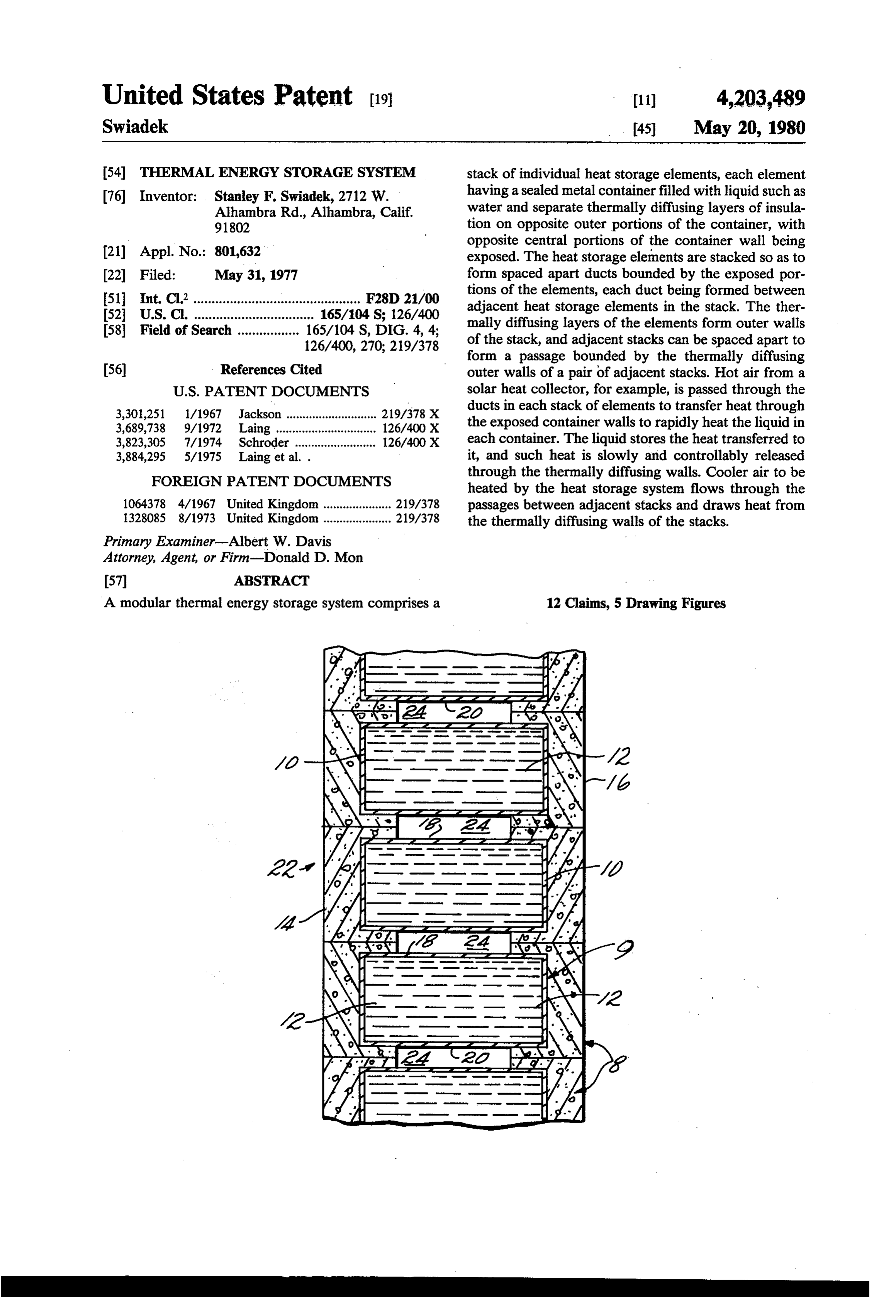
United States Patent (19) (11) 4,203,489 Swiadek 45 May 20, 1980 54 THERMAL ENERGY STORAGESYSTEM stack of individual heat storage elements, each element 76 Inventor: Stanley F. Swiadek, 2712 W. having a sealed metal container filled with liquid such as Alhambra Rd., Alhambra, Calif. water and separate thermally diffusing layers of insula 91802 tion on opposite outer portions of the container, with opposite central portions of the container wall being (21) Appl. No.: 801,632 exposed. The heat storage elements are stacked so as to (22 Filed: May 31, 1977 form spaced apart ducts bounded by the exposed por 51) Int. Cl’.............................................. F28D 21/00 tions of the elements, each duct being formed between 52 U.S.C. ................................. 165/104 S; 126/400 adjacent heat storage elements in the stack. The ther 58 Field of Search ................. 165/104 S, DIG. 4, 4; mally diffusing layers of the elements form outer walls 126/400, 270; 219/378 of the stack, and adjacent stacks can be spaced apart to form a passage bounded by the thermally diffusing 56) References Cited outer walls of a pair of adjacent stacks. Hot air from a
3,301,251 1/1967 Jackson ............................ 219/378 X ducts in each stack of elements to transfer heat through 3,689,738 9/1972 Laing ........ ... 126/400X the exposed container walls to rapidly heat the liquid in 3,823,305 7/1974 Schroder ......................... 126/400X each container. The liquid stores the heat transferred to 3,884,295 5/1975 Laing et al. . it, and such heat is slowly and controllably released FOREIGN PATENT DOCUMENTS through the thermally diffusing walls. Cooler air to be heated by the heat storage system flows through the 1064378 4/1967 United Kingdom ..................... 219/378 passages between adjacent stacks and draws heat from 1328085 8/1973 United Kingdom ..................... 219/378 the thermally diffusing walls of the stacks. Primary Examiner-Albert W. Davis
Attorney, Agent, or Firm-Donald D. Mon
A modular thermal energy storage system comprises a 12 Claims, 5 Drawing Figures
Page 2
Drawing sheet — no readable text.
Page 3
Drawing sheet — no readable text.
Page 4
1. - 2
Of the above materials, water has the highest SFM, but
THERMAL ENERGY STORAGESYSTEM heat storage systems using large tanks of water have the problems described above. Stainless steel, copper and
BACKGROUND OF THE INVENTION aluminum are good heat storage mediums, but the cost 5 of these materials is prohibitive if used largely in a heat
This invention relates to a thermal energy storage storage system. Granite has only slightly more than half system. The invention is especially useful in storing heat the SFM of water, but its low cost makes it competitive for a solar energy space-heating system.
The present invention is an improvement in heat for heat storage applications because a larger volume is storage systems over the heat storage means disclosed 10 all that is required for storing more heat, and such a system does not require heat exchangers, complex in the following patents:
plumbing, or the installation required by water systems.
Another factor to consider in selecting a heat storage
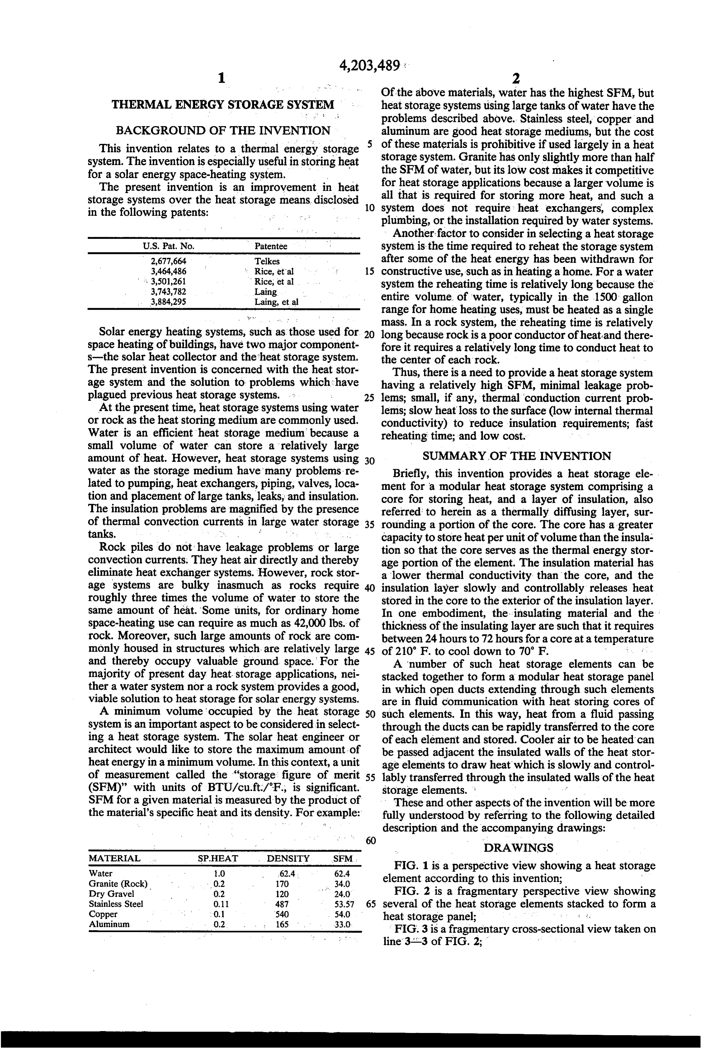
U.S. Pat, No, Patentee system is the time required to reheat the storage system 2,677,664 Telkes after some of the heat energy has been withdrawn for 3,464486 Rice, etal 15 constructive use, such as in heating a home. For a water '', 3,501,261 Rice, et a system the reheating time is relatively long because the
3,884,295 Laing, etal entire volume of water, typically in the 1500 gallon range for home heating uses, must be heated as a single mass. In a rock system, the reheating time is relatively
Solar energy heating systems, such as those used for 20 space heating of buildings, have two major component long because rock is a poor conductor of heat and there fore it requires a relatively long time to conduct heat to s-the solar heat collector and the heat storage system. the center of each rock.
The present invention is concerned with the heat stor Thus, there is a need to provide a heat storage system age system and the solution to problems which have having a relatively high SFM, minimal leakage prob plagued previous heat storage systems. :
At the present time, heat storage systems using water lems; small, if any, thermal conduction current prob
lems; slow heat loss to the surface (low internal thermal or rock as the heat storing medium are commonly used. conductivity) to reduce insulation requirements; fast Water is an efficient heat storage medium because a reheating time; and low cost. small volume of water can store a relatively large amount of heat. However, heat storage systems using SUMMARY OF THE INVENTION water as the storage medium have many problems re Briefly, this invention provides a heat storage ele lated to pumping, heat exchangers, piping, valves, loca ment for a modular heat storage system comprising a tion and placement of large tanks, leaks, and insulation. core for storing heat, and a layer of insulation, also The insulation problems are magnified by the presence referred to herein as a thermally diffusing layer, sur of thermal convection currents in large water storage 35 rounding a portion of the core. The core has a greater capacity to store heat per unit of volume than the insula
Rock piles do not have leakage problems or large tion so that the core serves as the thermal energy stor convection currents. They heat air directly and thereby age portion of the element. The insulation material has eliminate heat exchanger systems. However, rock stor a lower thermal conductivity than the core, and the age systems are bulky inasmuch as rocks require insulation layer slowly and controllably releases heat roughly three times the volume of water to store the stored in the core to the exterior of the insulation layer. same amount of heat. Some units, for ordinary home In one embodiment, the insulating material and the space-heating use can require as much as 42,000 lbs. of thickness of the insulating layer are such that it requires rock. Moreover, such large amounts of rock are com between 24 hours to 72 hours for a core at a temperature monly housed in structures which are relatively large 45 of 20 F. to cool down to 70 F. . ... . and thereby occupy valuable ground space. For the A number of such heat storage elements can be majority of present day heat-storage applications, nei stacked together to form a modular heat storage panel ther a water system nor a rock system provides a good, in which open ducts extending through such elements viable solution to heat storage for solar energy systems. are in fluid communication with heat storing cores of A minimum volume occupied by the heat storage 50 such elements. In this way, heat from a fluid passing system is an important aspect to be considered in select through the ducts can be rapidly transferred to the core ing a heat storage system. The solar heat engineer or of each element and stored. Cooler air to be heated can architect would like to store the maximum amount of be passed adjacent the insulated walls of the heat stor heat energy in a minimum volume. In this context, a unit age elements to draw heat which is slowly and control of measurement called the "storage figure of merit 55 lably transferred through the insulated walls of the heat (SFM)” with units of BTU/cu ft/'F., is significant. storage elements. a SFM for a given material is measured by the product of These and other aspects of the invention will be more the material's specific heat and its density. For example: fully understood by referring to the following detailed description and the accompanying drawings:
DRAWINGS
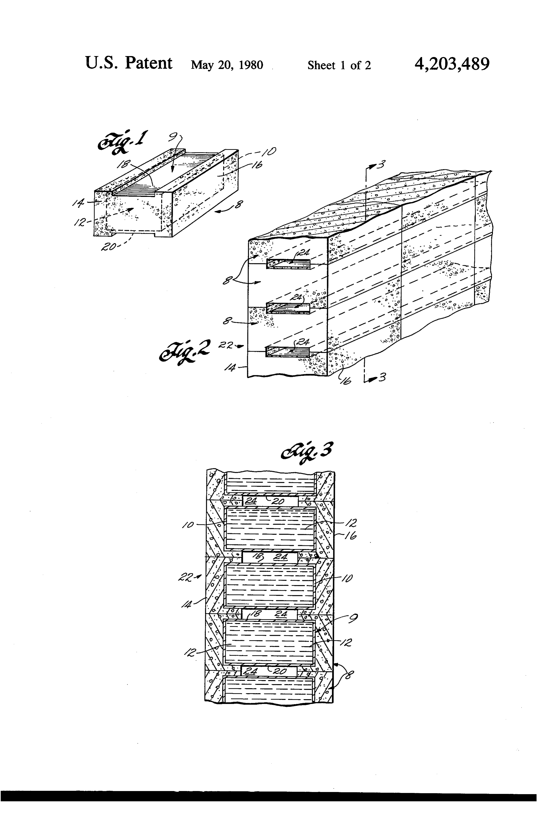
FIG. 1 is a perspective view showing a heat storage
Granite (Rock) 0.2 70 34.0 element according to this invention; Dry Gravel 0.2 120 24.0 FIG. 2 is a fragmentary perspective view showing Stainless Steel 0.1 487 53.57 65 several of the heat storage elements stacked to form a Copper 0.1 540 54,0 heat storage panel; 8 :
FIG. 3 is a fragmentary cross-sectional view taken on
Page 5
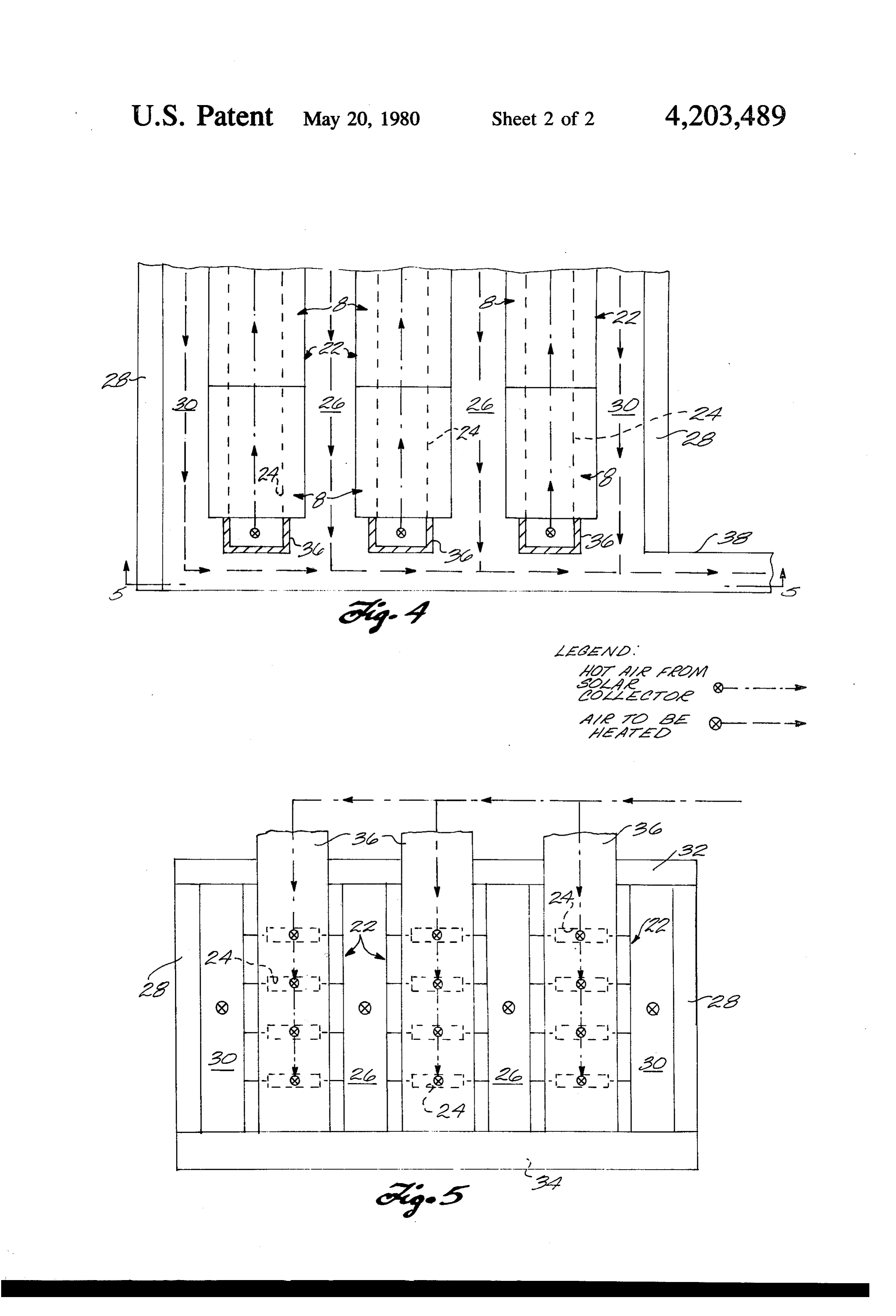
FIG. 4 is a fragmentary plan view showing a heat away from the side walls of the container, and one-half storage system having several panels comprising stacks inch thick extending away from each end wall of the of the heat storage elements; and container as well as the top and bottom walls of the FIG. 5 is a fragmentary elevation view taken on lines container.
5-5 of FIG. 4. The material used for the insulation layer has a lower
DETAILED DESCRIPTION
thermal conductivity than the material from which the core 9 is made. Conversely, the material used for the
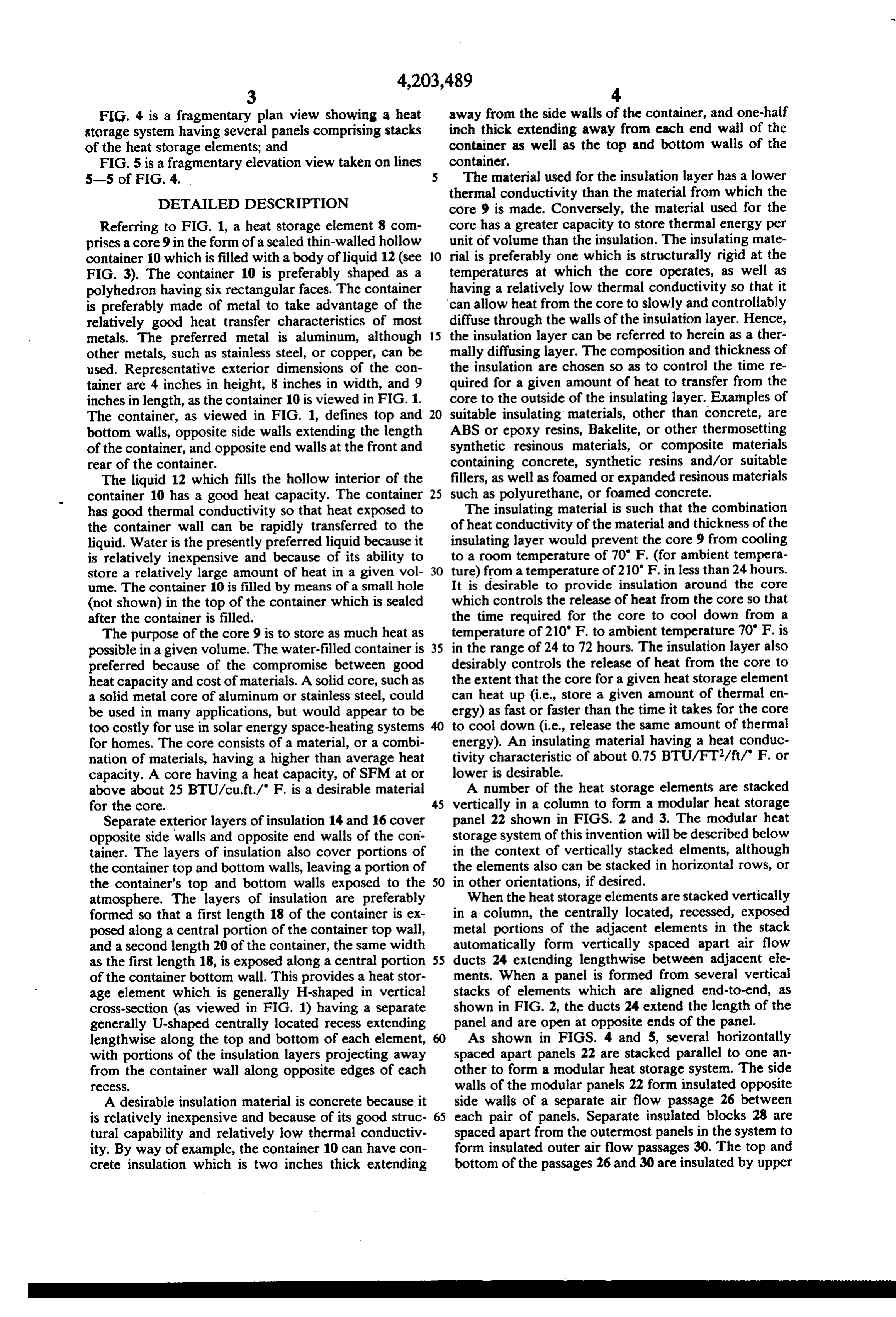
Referring to FIG. 1, a heat storage element 8 com core has a greater capacity to store thermal energy per prises a core 9 in the form of a sealed thin-walled hollow unit of volume than the insulation. The insulating mate container 10 which is filled with a body of liquid 12 (see O rial is preferably one which is structurally rigid at the FIG. 3). The container 10 is preferably shaped as a temperatures at which the core operates, as well as polyhedron having six rectangular faces. The container having a relatively low thermal conductivity so that it is preferably made of metal to take advantage of the can allow heat from the core to slowly and controllably relatively good heat transfer characteristics of most diffuse through the walls of the insulation layer. Hence, metals. The preferred metal is aluminum, although 15 the insulation layer can be referred to herein as a ther other metals, such as stainless steel, or copper, can be mally diffusing layer. The composition and thickness of used. Representative exterior dimensions of the con the insulation are chosen so as to control the time re tainer are 4 inches in height, 8 inches in width, and 9 quired for a given amount of heat to transfer from the inches in length, as the container 10 is viewed in FIG. 1. core to the outside of the insulating layer. Examples of The container, as viewed in FIG. 1, defines top and 20 suitable insulating materials, other than concrete, are bottom walls, opposite side walls extending the length ABS or epoxy resins, Bakelite, or other thermosetting of the container, and opposite end walls at the front and synthetic resinous materials, or composite materials rear of the container. containing concrete, synthetic resins and/or suitable The liquid 12 which fills the hollow interior of the fillers, as well as foamed or expanded resinous materials container 10 has a good heat capacity. The container 25 such as polyurethane, or foamed concrete. has good thermal conductivity so that heat exposed to The insulating material is such that the combination the container wall can be rapidly transferred to the of heat conductivity of the material and thickness of the liquid. Water is the presently preferred liquid because it insulating layer would prevent the core 9 from cooling is relatively inexpensive and because of its ability to to a room temperature of 70 F. (for ambient tempera store a relatively large amount of heat in a given vol 30 ture) from a temperature of 210" F. in less than 24 hours. ume. The container 10 is filled by means of a small hole It is desirable to provide insulation around the core (not shown) in the top of the container which is sealed which controls the release of heat from the core so that after the container is filled. the time required for the core to cool down from a The purpose of the core 9 is to store as much heat as temperature of 210' F. to ambient temperature 70' F. is possible in a given volume. The water-filled container is 35 in the range of 24 to 72 hours. The insulation layer also preferred because of the compromise between good desirably controls the release of heat from the core to heat capacity and cost of materials. A solid core, such as the extent that the core for a given heat storage element a solid metal core of aluminum or stainless steel, could can heat up (i.e., store a given amount of thermal en be used in many applications, but would appear to be ergy) as fast or faster than the time it takes for the core too costly for use in solar energy space-heating systems to cool down (i.e., release the same amount of thermal for homes. The core consists of a material, or a combi energy). An insulating material having a heat conduc nation of materials, having a higher than average heat tivity characteristic of about 0.75 BTU/FT2/ft/" F. or capacity. A core having a heat capacity, of SFM at or lower is desirable.
above about 25 BTU/cu. ft./ F. is a desirable material A number of the heat storage elements are stacked for the core. 45 vertically in a column to form a modular heat storage Separate exterior layers of insulation 14 and 16 cover panel 22 shown in FIGS. 2 and 3. The modular heat opposite side walls and opposite end walls of the con storage system of this invention will be described below tainer. The layers of insulation also cover portions of in the context of vertically stacked elments, although the container top and bottom walls, leaving a portion of the elements also can be stacked in horizontal rows, or the container's top and bottom walls exposed to the 50 in other orientations, if desired. atmosphere. The layers of insulation are preferably When the heat storage elements are stacked vertically formed so that a first length 18 of the container is ex in a column, the centrally located, recessed, exposed posed along a central portion of the container top wall, metal portions of the adjacent elements in the stack and a second length 20 of the container, the same width automatically form vertically spaced apart air flow as the first length 18, is exposed along a central portion 55 ducts 24 extending lengthwise between adjacent ele of the container bottom wall. This provides a heat stor ments. When a panel is formed from several vertical age element which is generally H-shaped in vertical stacks of elements which are aligned end-to-end, as cross-section (as viewed in FIG. 1) having a separate shown in FIG. 2, the ducts 24 extend the length of the generally U-shaped centrally located recess extending panel and are open at opposite ends of the panel. lengthwise along the top and bottom of each element, 60 As shown in FIGS. 4 and 5, several horizontally with portions of the insulation layers projecting away spaced apart panels 22 are stacked parallel to one an from the container wall along opposite edges of each other to form a modular heat storage system. The side TeCeSS. walls of the modular panels 22 form insulated opposite A desirable insulation material is concrete because it side walls of a separate air flow passage 26 between is relatively inexpensive and because of its good struc 65 each pair of panels. Separate insulated blocks 28 are tural capability and relatively low thermal conductiv spaced apart from the outermost panels in the system to ity. By way of example, the container 10 can have con form insulated outer air flow passages 30. The top and crete insulation which is two inches thick extending bottom of the passages 26 and 30 are insulated by upper
Page 6
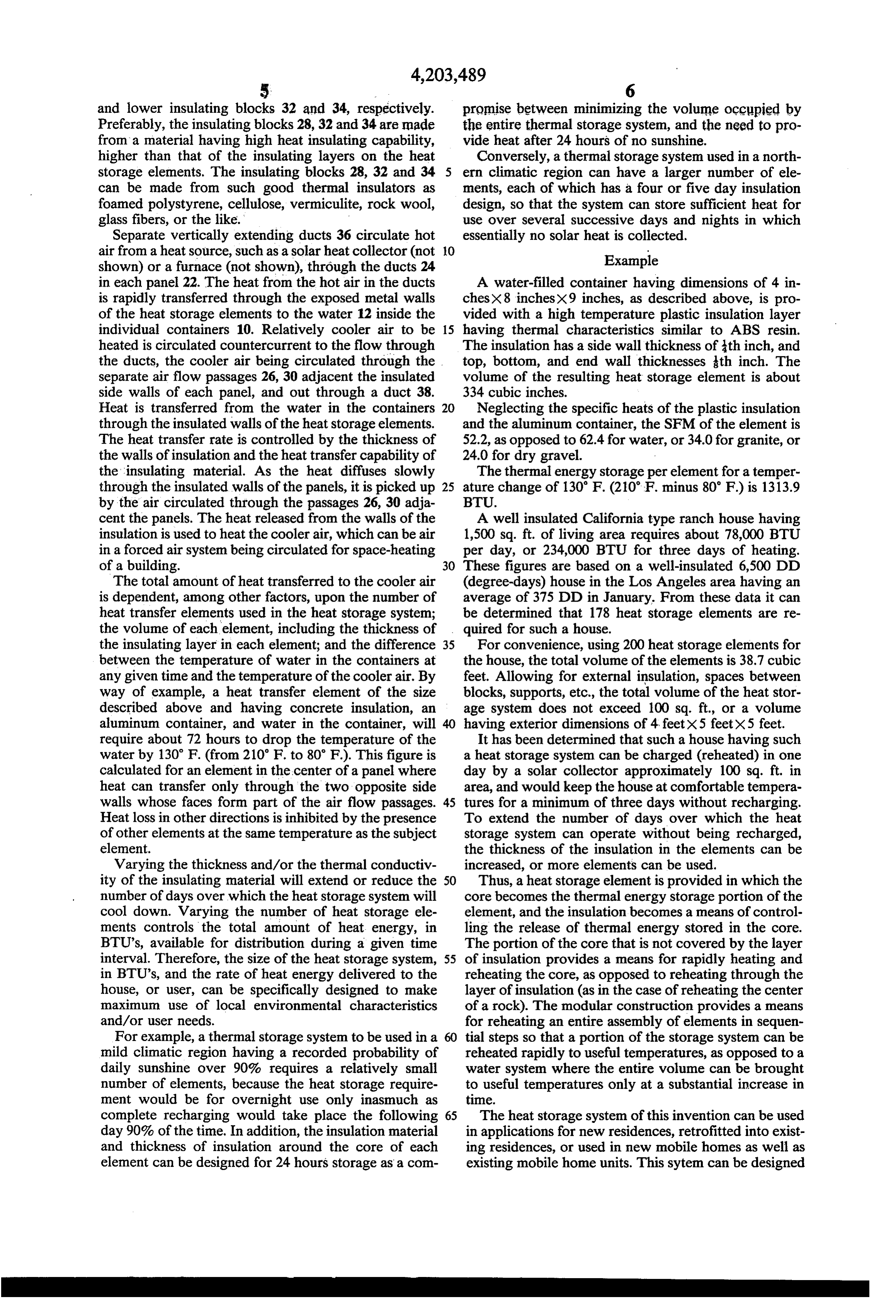
5. - 6 and lower insulating blocks 32 and 34, respectively. promise between minimizing the volume occupied by Preferably, the insulating blocks 28, 32 and 34 are made the entire thermal storage system, and the need to pro from a material having high heat insulating capability, vide heat after 24 hours of no sunshine. higher than that of the insulating layers on the heat Conversely, a thermal storage system used in a north storage elements. The insulating blocks 28, 32 and 34 ern climatic region can have a larger number of ele can be made from such good thermal insulators as ments, each of which has a four or five day insulation foamed polystyrene, cellulose, vermiculite, rock wool, design, so that the system can store sufficient heat for glass fibers, or the like." use over several successive days and nights in which Separate vertically extending ducts 36 circulate hot essentially no solar heat is collected. air from a heat source, such as a solar heat collector (not O Example shown) or a furnace (not shown), through the ducts 24 in each panel 22. The heat from the hot air in the ducts A water-filled container having dimensions of 4 in is rapidly transferred through the exposed metal walls chesX8 inches)x9 inches, as described above, is pro of the heat storage elements to the water 12 inside the vided with a high temperature plastic insulation layer individual containers 10. Relatively cooler air to be 15 having thermal characteristics similar to ABS resin. heated is circulated countercurrent to the flow through The insulation has a side wall thickness of th inch, and the ducts, the cooler air being circulated through the top, bottom, and end wall thicknesses th inch. The separate air flow passages 26, 30 adjacent the insulated volume of the resulting heat storage element is about side walls of each panel, and out through a duct 38. 334 cubic inches.
Heat is transferred from the water in the containers Neglecting the specific heats of the plastic insulation through the insulated walls of the heat storage elements. and the aluminum container, the SFM of the element is The heat transfer rate is controlled by the thickness of 52.2, as opposed to 62.4 for water, or 34.0 for granite, or the walls of insulation and the heat transfer capability of 24.0 for dry gravel.
the insulating material. As the heat diffuses slowly The thermal energy storage per element for a temper through the insulated walls of the panels, it is picked up 25 ature change of 130 F. (210 F. minus 80 F) is 1313.9 by the air circulated through the passages 26, 30 adja BTU.
cent the panels. The heat released from the walls of the A well insulated California type ranch house having insulation is used to heat the cooler air, which can be air 1,500 sq. ft. of living area requires about 78,000 BTU in a forced air system being circulated for space-heating per day, or 234,000 BTU for three days of heating. of a building. 30 These figures are based on a well-insulated 6,500 DD The total amount of heat transferred to the cooler air (degree-days) house in the Los Angeles area having an is dependent, among other factors, upon the number of average of 375 DD in January. From these data it can heat transfer elements used in the heat storage system; be determined that 178 heat storage elements are re the volume of each element, including the thickness of quired for such a house.
the insulating layer in each element; and the difference 35 For convenience, using 200 heat storage elements for between the temperature of water in the containers at the house, the total volume of the elements is 38.7 cubic any given time and the temperature of the cooler air. By feet. Allowing for external insulation, spaces between way of example, a heat transfer element of the size blocks, supports, etc., the total volume of the heat stor described above and having concrete insulation, an age system does not exceed 100 sq. ft., or a volume aluminum container, and water in the container, will having exterior dimensions of 4 feetx5 feetx5 feet. require about 72 hours to drop the temperature of the It has been determined that such a house having such water by 130 F. (from 210 F. to 80 F). This figure is a heat storage system can be charged (reheated) in one calculated for an element in the center of a panel where day by a solar collector approximately 100 sq. ft. in heat can transfer only through the two opposite side area, and would keep the house at comfortable tempera walls whose faces form part of the air flow passages. 45 tures for a minimum of three days without recharging. Heat loss in other directions is inhibited by the presence To extend the number of days over which the heat of other elements at the same temperature as the subject storage system can operate without being recharged, element. the thickness of the insulation in the elements can be Varying the thickness and/or the thermal conductiv increased, or more elements can be used. ity of the insulating material will extend or reduce the 50 Thus, aheat storage element is provided in which the number of days over which the heat storage system will core becomes the thermal energy storage portion of the cool down. Varying the number of heat storage ele element, and the insulation becomes a means of control ments controls the total amount of heat energy, in ling the release of thermal energy stored in the core. BTU's, available for distribution during a given time The portion of the core that is not covered by the layer interval. Therefore, the size of the heat storage system, 55 of insulation provides a means for rapidly heating and in BTU's, and the rate of heat energy delivered to the reheating the core, as opposed to reheating through the house, or user, can be specifically designed to make layer of insulation (as in the case of reheating the center maximum use of local environmental characteristics of a rock). The modular construction provides a means and/or user needs. for reheating an entire assembly of elements in sequen For example, a thermal storage system to be used in a 60 tial steps so that a portion of the storage system can be mild climatic region having a recorded probability of reheated rapidly to useful temperatures, as opposed to a daily sunshine over 90% requires a relatively small water system where the entire volume can be brought number of elements, because the heat storage require to useful temperatures only at a substantial increase in ment would be for overnight use only inasmuch as time.
complete recharging would take place the following 65 The heat storage system of this invention can be used day 90% of the time. In addition, the insulation material in applications for new residences, retrofitted into exist and thickness of insulation around the core of each ing residences, or used in new mobile homes as well as element can be designed for 24 hours storage as a com existing mobile home units. This sytem can be designed
Page 7
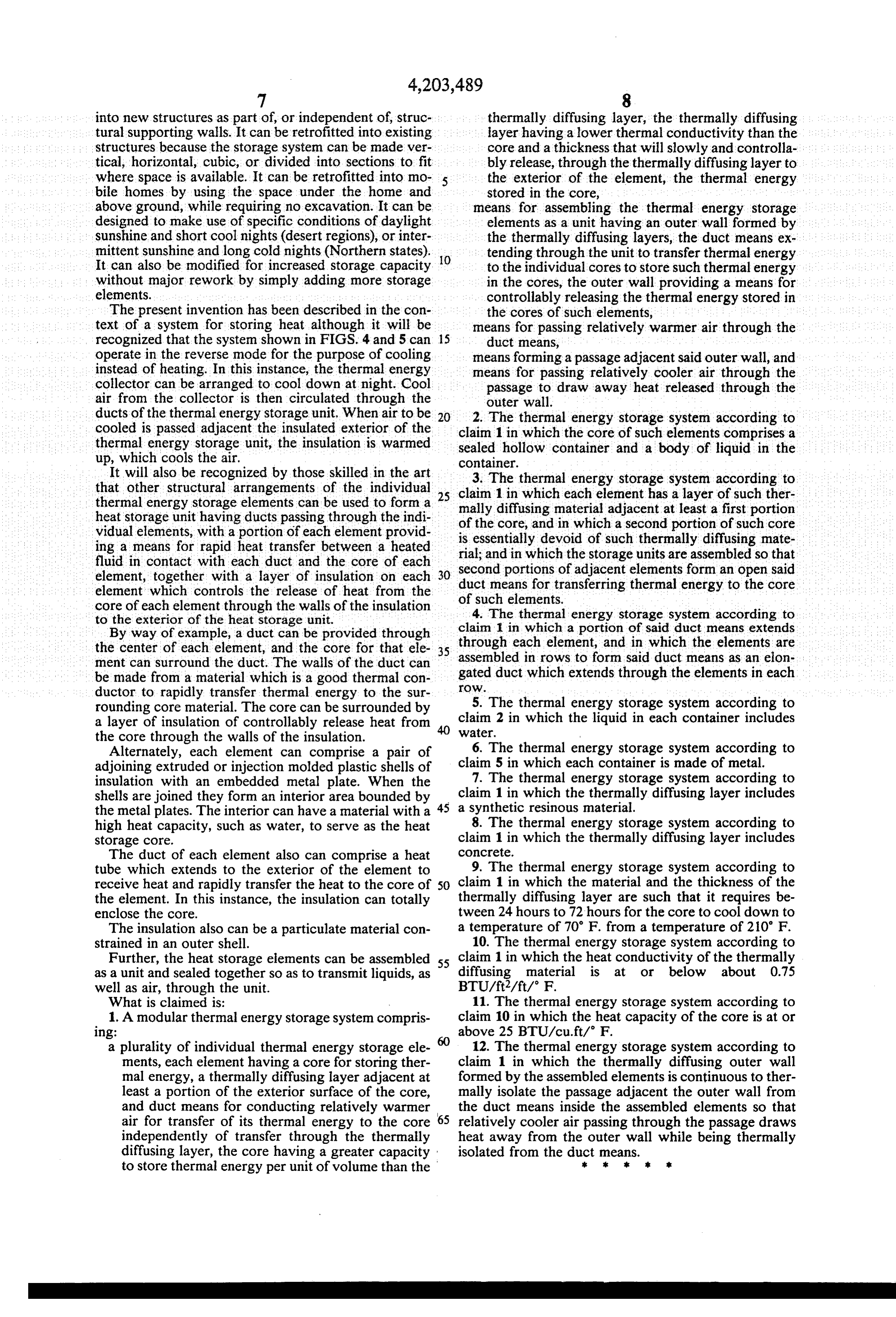
into new structures as part of, or independent of, struc thermally diffusing layer, the thermally diffusing tural supporting walls. It can be retrofitted into existing layer having a lower thermal conductivity than the structures because the storage system can be made ver core and a thickness that will slowly and controlla tical, horizontal, cubic, or divided into sections to fit bly release, through the thermally diffusing layer to where space is available. It can be retrofitted into mo 5 the exterior of the element, the thermal energy bile homes by using the space under the home and stored in the core, above ground, while requiring no excavation. It can be means for assembling the thermal energy storage designed to make use of specific conditions of daylight elements as a unit having an outer wall formed by Sunshine and short cool nights (desert regions), or inter the thermally diffusing layers, the duct means ex mittent sunshine and long cold nights (Northern states). O tending through the unit to transfer thermal energy It can also be modified for increased storage capacity to the individual cores to store such thermal energy without major rework by simply adding more storage in the cores, the outer wall providing a means for elements. controllably releasing the thermal energy stored in The present invention has been described in the con the cores of such elements, text of a system for storing heat although it will be means for passing relatively warmer air through the recognized that the system shown in FIGS. 4 and 5 can 15 duct means, operate in the reverse mode for the purpose of cooling means forming a passage adjacent said outer wall, and instead of heating. In this instance, the thermal energy means for passing relatively cooler air through the collector can be arranged to cool down at night. Cool passage to draw away heat released through the air from the collector is then circulated through the outer wall.
ducts of the thermal energy storage unit. When air to be 2. The thermal energy storage system according to cooled is passed adjacent the insulated exterior of the claim 1 in which the core of such elements comprises a thermal energy storage unit, the insulation is warmed sealed hollow container and a body of liquid in the up, which cools the air. container.
It will also be recognized by those skilled in the art 3. The thermal energy storage system according to that other structural arrangements of the individual 25 claim 1 in which each element has a layer of such ther thermal energy storage elements can be used to form a mally diffusing material adjacent at least a first portion heat storage unit having ducts passing through the indi of the core, and in which a second portion of such core vidual elements, with a portion of each element provid is essentially devoid of such thermally diffusing mate ing a means for rapid heat transfer between a heated rial; and in which the storage units are assembled so that fluid in contact with each duct and the core of each element, together with a layer of insulation on each 30 second portions of adjacent elements form an open said duct means for transferring thermal energy to the core element which controls the release of heat from the of such elements.
core of each element through the walls of the insulation 4. The thermal energy storage system according to to the exterior of the heat storage unit. claim 1 in which a portion of said duct means extends By way of example, a duct can be provided through through each element, and in which the elements are the center of each element, and the core for that ele 35 assembled ment can surround the duct. The walls of the duct can in rows to form said duct means as an eion be made from a material which is a good thermal con gated OW.
duct which extends through the elements in each ductor to rapidly transfer thermal energy to the sur 5. The thermal energy storage system according to rounding core material. The core can be surrounded by claim 2 in which the liquid in each container includes a layer of insulation of controllably release heat from 40 Water.
the core through the walls of the insulation. 6. The thermal energy storage system according to Alternately, each element can comprise a pair of adjoining extruded or injection molded plastic shells of claim 5 in which each container is made of metal. insulation with an embedded metal plate. When the 7. The thermal energy storage system according to shells are joined they form an interior area bounded by 45 claim 1 in which the thermally diffusing layer includes the metal plates. The interior can have a material with a a synthetic resinous material.
high heat capacity, such as water, to serve as the heat 8. The thermal energy storage system according to storage core. claim 1 in which the thermally diffusing layer includes The duct of each element also can comprise a heat concrete.
tube which extends to the exterior of the element to 9. The thermal energy storage system according to receive heat and rapidly transfer the heat to the core of 50 claim 1 in which the material and the thickness of the the element. In this instance, the insulation can totally thermally diffusing layer are such that it requires be enclose the core. tween 24 hours to 72 hours for the core to cool down to The insulation also can be a particulate material con a temperature of 70 F. from a temperature of 210' F. strained in an outer shell. 10. The thermal energy storage system according to Further, the heat storage elements can be assembled 55 claim 1 in which the heat conductivity of the thermally as a unit and sealed together so as to transmit liquids, as diffusing material is at or below about 0.75 well as air, through the unit. BTU/ft2/ft/ F.
What is claimed is: 11. The thermal energy storage system according to 1. A modular thermal energy storage system compris claim 10 in which the heat capacity of the core is at or 1ng: above 25 BTU/cu. ft/ F.
a plurality of individual thermal energy storage ele 12. The thermal energy storage system according to ments, each element having a core for storing ther claim 1 in which the thermally diffusing outer wall mal energy, a thermally diffusing layer adjacent at formed by the assembled elements is continuous to ther least a portion of the exterior surface of the core, mally isolate the passage adjacent the outer wall from and duct means for conducting relatively warmer the duct means inside the assembled elements so that air for transfer of its thermal energy to the core relatively cooler air passing through the passage draws independently of transfer through the thermally heat away from the outer wall while being thermally diffusing layer, the core having a greater capacity isolated from the ducts means.
to store thermal energy per unit of volume than the
Provenance
- Collection
- Cited prior art
- Original PDF
- patentimages.storage.googleapis.com →
- Filed
- 1977-05-31
- Pages
- 7
- Method
- pdftotext (the PDF's own text layer) + pdftoppm 300dpi page scans
- Source
- Google Patents bibliographic record
- Granted
- 1980-05-20
- Inventors
- Stanley F. Swiadek
- Transcribed from
- patentimages.storage.googleapis.com →