patent · US4389085
Lighting system utilizing the sunlight
21 June 1983
Page 1 — bibliographic record
United States Patent (19) (11) 4,389,085 Mori 45 Jun. 21, 1983 (54) LIGHTING SYSTEM UTILIZING THE 4,195,907 4/1980 Zamja et al. ..................... 350/96.10 SUNLGHT 4,196,962 4/1980 Sick .............. ... 350/96.10 4,201,197 5/1980 Dismer. ... 350/96.10 76 Inventor: Kei Mori, 3-16-3-501, Kaminoge, 4,289,118 9/1981 Stark ................................... 126/438 Setagaya-ku, Tokyo, Japan 4,297,000 10/1981 Fries ......... ... 350/96.24 4,297,521 0/1981 Johnson .............................. 126/438 (21) Appl. No.: 216,838 4,302,069 11/1981 Niemi ........... ... 350/96.10 (22 Filed: Dec. 16, 1981 4,312,330 1/1982 Holdridge ........................... 26/440 4,312,709 / 1982 Stark et al. ... ... 126/440 (30) Foreign Application Priority Data 4,325,788 4/1982 Snyder ................................ 26/440 Feb. 22, 1978 JP Japan .................................. 53-19439 OTHER PUBLICATIONS
Mar. 9, 1978 JP Japan .................................. 53-2.7065
May 9, 1978 JP Japan .................................. 53-54122 NASA Tech. Briefs, Summer 1978, Langley Research May 30, 1978 JP Japan .................................. 53-64.775 Center, Hampton, VA, Edwards, "Optics for Natural Jun. 14, 1978 (JP) Japan .................................. 53-71844 Lighting', pp. 209-211.
Jul. 3, 1978 JP Japan .................................. 53-80630 Primary Examiner-John D. Lee
Aug. 19, 1978 (JP) Japan ................................ 53-10307 Assistant Examiner-Frank Gonzalez Oct. 16, 1978 JP Japan ................................ 53-127184 Attorney, Agent, or Firm-Burgess, Ryan and Wayner 51) Int. Cl............................................... GO2BS/172 52 U.S. C. .............................. 350/96.10; 350/96.18; (57 ABSTRACT 350/258 A lighting system utilizing the sunlight comprising in 58 Field of Search .................. 350/96.10, 96.18, 258; general an optical system for focusing the sun rays at a 353/3; 237/1 R; 126/431, 438, 440 point, an optical transmission line consisting of optical (56) References Cited conductor means with light diffusion holes for transmit
desired point, and an optical system for redistributing 2,022,144 11/1935 Nicolson ................................. 353/3 the sun rays transmitted through the optical transmis 2,920,710 1/1960 Howard ....... ... 350/96.10 sion line into at least one desired space or spot. 3,535,018 10/1970 Vasilatos. ... 350/96.24 3,656,844 4/1972 Botskor ................................... 353/3 4,078,548 3/1978 Kapany ............................ 350/96.10 10 Claims, 34 Drawing Figures
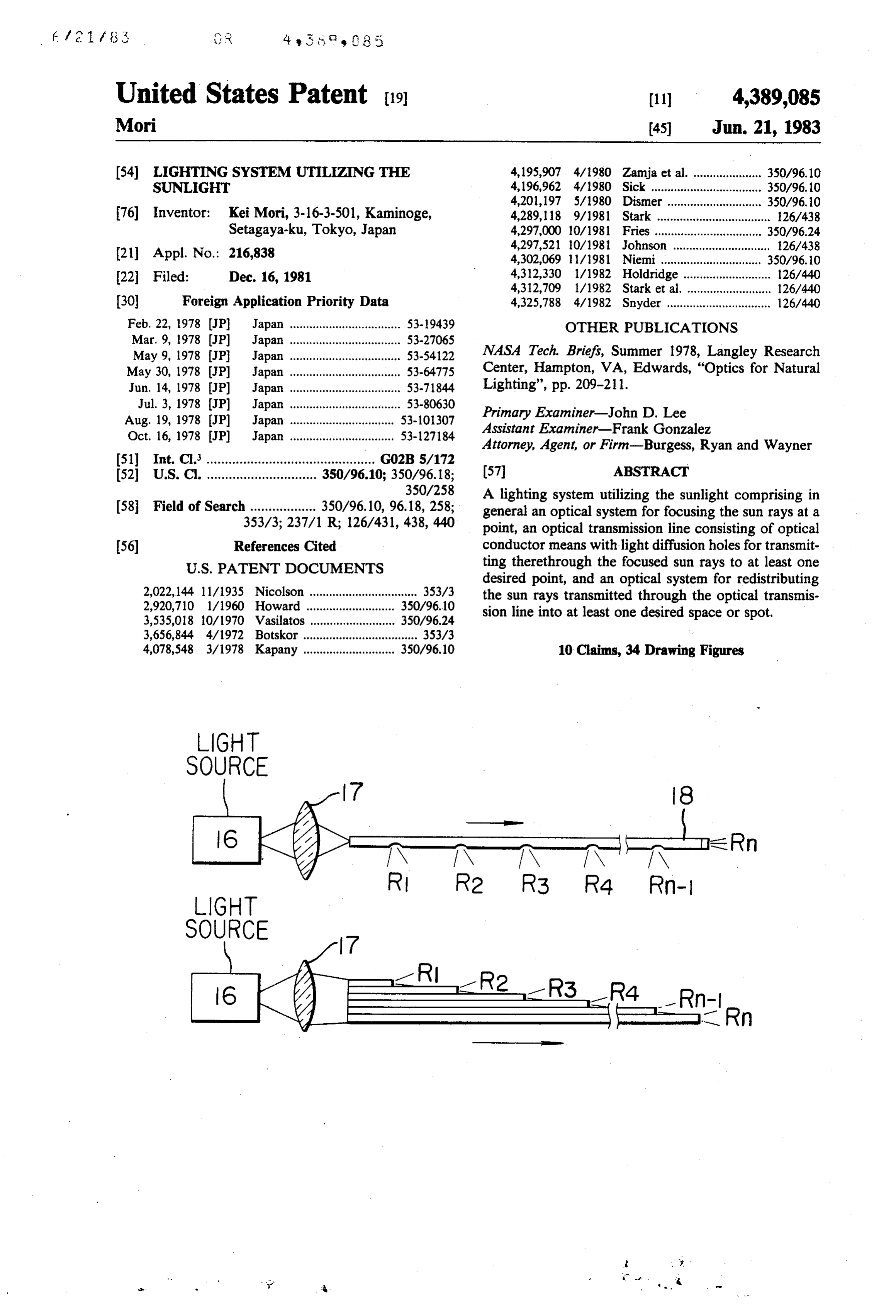
LIGHT
SOURCE
Page 2
Drawing sheet — no readable text.
Page 3
Drawing sheet — no readable text.
Page 4
Drawing sheet — no readable text.
Page 5
Drawing sheet — no readable text.
Page 6
Drawing sheet — no readable text.
Page 7
Drawing sheet — no readable text.
Page 8
Drawing sheet — no readable text.
Page 9
Drawing sheet — no readable text.
Page 10
Drawing sheet — no readable text.
Page 11
Drawing sheet — no readable text.
Page 12
Drawing sheet — no readable text.
Page 13
Drawing sheet — no readable text.

Page 14
Drawing sheet — no readable text.
Page 15
Drawing sheet — no readable text.
Page 16
Drawing sheet — no readable text.
Page 17
In the case of the lighting or illumination systems for
LIGHTING SYSTEM UTILIZNG THE SUNLIGHT tunnels and pits, electric lighting or illumination has been widely used so that the high cost of electricity
This is a continuation, of application Ser. No. 10,053, presents a problem. When a private electric installation filed Feb. 7, 1979, now abandoned. is used because for instance a commercial electric sup BACKGROUND OF THE INVENTION ply is not readily available or for other purposes, the installation cost as well as the maintenance cost be
The present invention relates to a lighting system comes very high.
utilizing the sunlight, which may collect the sunlight at Meanwhile for use in optical communications sys a place which is normally showered with the sun rays 10 tems which are much more efficient and economical, and transmit the collected sunlight to another place extensive research and development respecting optical where the direct access to the sun rays is impossible. fibers has been conducted. Now optical fibers are Solar energy has been considered and is still consid readily available which are highly transparent, with ered to become available as the most promising and resultant reduction in transmission or propagation important source of infinite and pollution-free energy 15 losses. In practice, bundles of optical fibers have been by the end of the 20th century for all the people living used for directing illuminating light from one place to on the Earth. However, the solar constant is so low than another. Thus with the optical fibers or optical conduc an extremely large solar energy collection installation is tors the solar light energy collected may be transmitted required so that the collected solar energy may be con from one place to another at a high efficiency. How verted into electrical energy in sufficient quantity so 20 ever, the optical fibers for optical communications use that it may be used successfully in practice. For in available in the market are in general about 0.1 mm in stance, a large number of solar cells are arrayed in a vast diameter. It is apparent that it is extremely difficult to area so as to convert the solar energy into electrical transmit the highly concentrated solar light energy energy which in turn is transmitted to a desired destina through an optical fiber of such extremely small diame tion. 25 ter. When light from the Sun is focused through a con Another serious problem encountered in the practical ventional optical system, its image has a diameter far utilization of solar energy is a low conversion efficiency greater than about 0.1 mm so that the solar energy with which the solar energy is converted into electric cannot be introduced into the optical fiber. Thus with energy. Furthermore, the electric energy thus obtained conventional optical fibers, the effective transmission of is further converted into other useful forms of energy 30 the collected solar energy from one place to another is such as mechanical energy, light energy and so on. Thus almost impossible in practice.
low conversion efficiencies are accumulated resulting in the use of only an extremely small fraction of the solar SUMMARY OF THE INVENTION energy collected. Accordingly, one of the objects of the present inven Meanwhile, large buildings have been constructed in 35 tion is to provide a lighting system utilizing the sunlight, urban areas and these buildings are in general built air which may collect the sunlight at one place and trans tight in order to economize the energy required for air mit the collected sunlight to a desired place where di conditioning. As a result there has been a problem of rect access to the sunlight is impossible, without the how to provide highly reliable and dependable emer conversion of solar energy into electrical energy for gency stand-by lighting or illumination systems at emer 40 transmission, whereby the illumination with the sun gency exits along emergency staircases and in totally light in a desired area may be suitably controlled and an enclosed rooms so as to ensure safe and quick evacua area or a place where the direct access to the sunlight is tion of people inside buildings in the case of an emer impossible may be illuminated with sunlight. gency such as a fire, an earthquake or the like. Further Another object of the present invention is to provide more, there has been an increasing demand for inexpen 45 a lighting system utilizing the sunlight wherein the sun sive, safe and simple lighting or illumination systems for light may be advantageously used as a light source tunnels and mine pits. during the daytime; and only when the sunlight is not In the conventional emergency stand-by lighting or sufficiently available, an artificial light source may be illumination systems, there is provided a stand-by elec used so that the consumption of electric energy may be tric source such as batteries or generators indepen 50 drastically reduced.
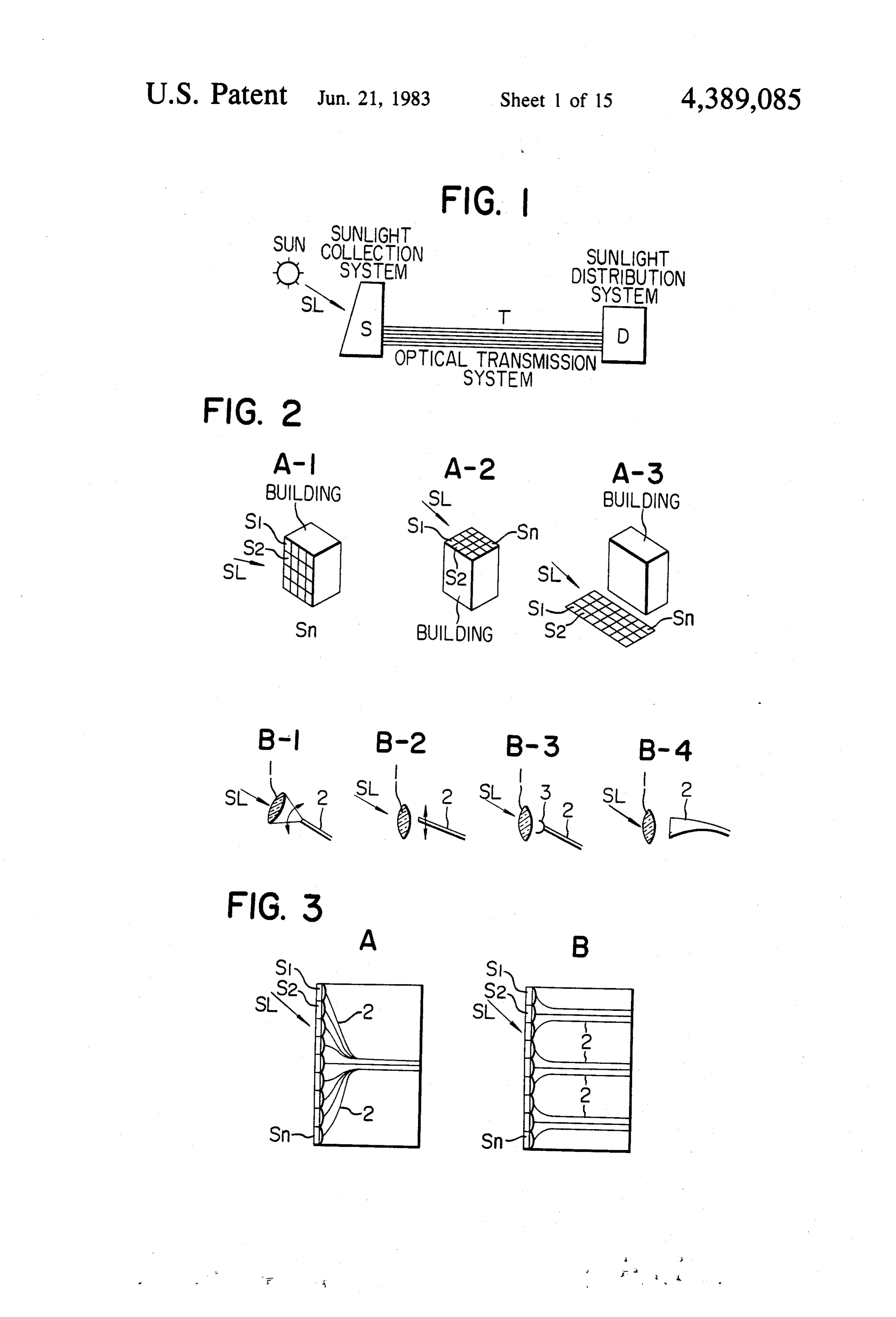
dently of the commercial electric supply. In addition, Another object of the present invention is to provide emergency lamps must be provided independently of the lighting system which may be considerably simpli the lighting or illumination systems normally used. fied and safeguarded against damages to such an extent Thus the inspection and maintenance of the emergency hitherto never attainable by any conventional lighting stand-by lighting or illumination systems are very cum 55 or illumination systems and consequently the inspection bersome and expensive. Furthermore, there is a fear and maintenance may be remarkably facilitated and that the stand-by electric sources and illumination lamps simplified with the resultant reduction in running cost. may be damaged in the case of an earthquake, and the A further object of the present invention is to provide service life of the electric source is in general short. a sunlight or solar light energy collection system capa Thus the conventional emergency stand-by lighting or ble of collecting the sunbeam or solar energy at an illumination systems are not completely reliable. Espe extremely higher degree of efficiency hitherto unattain cially in the case of the emergency stand-by lighting or able by any prior art solar energy collection systems. illumination systems installed in large buildings, the BRIEF DESCRIPTION OF THE DRAWINGS reliability thereof is of great importance during the daytime when concentrations of people are extremely 65 FIG. 1 is a view illustrating the underlying principle high. Thus the conventional emergency stand-by light of the present invention;
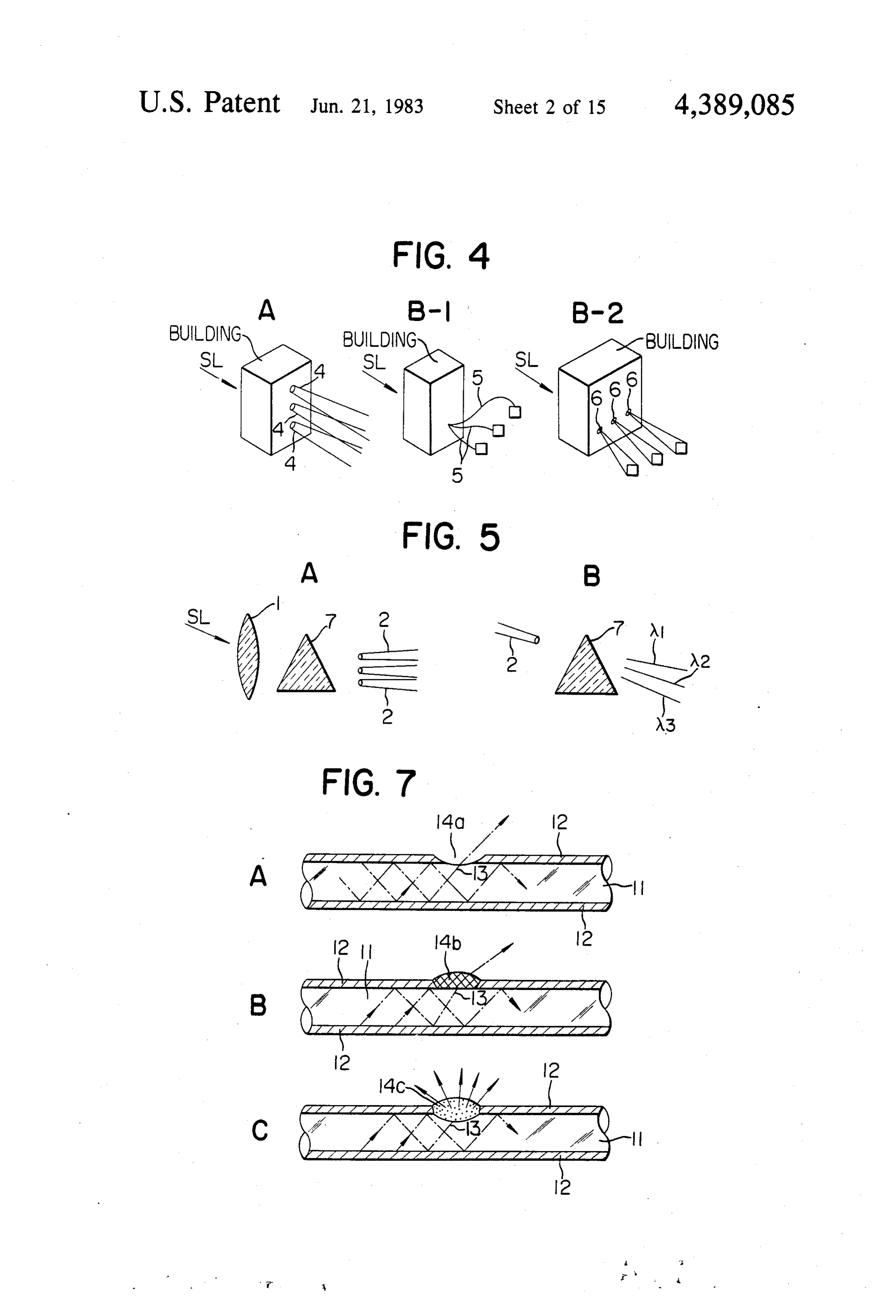
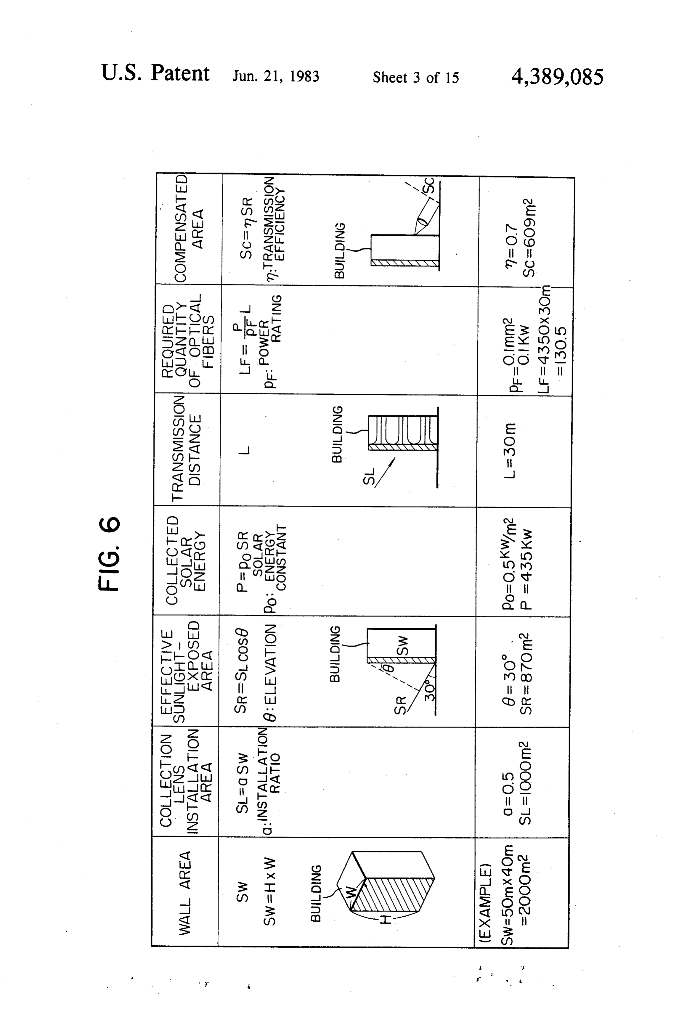
ing or illumination systems have many problems to be FIG. 2 shows various types of sunlight collectors Overcoe. used in the present invention;
Page 18
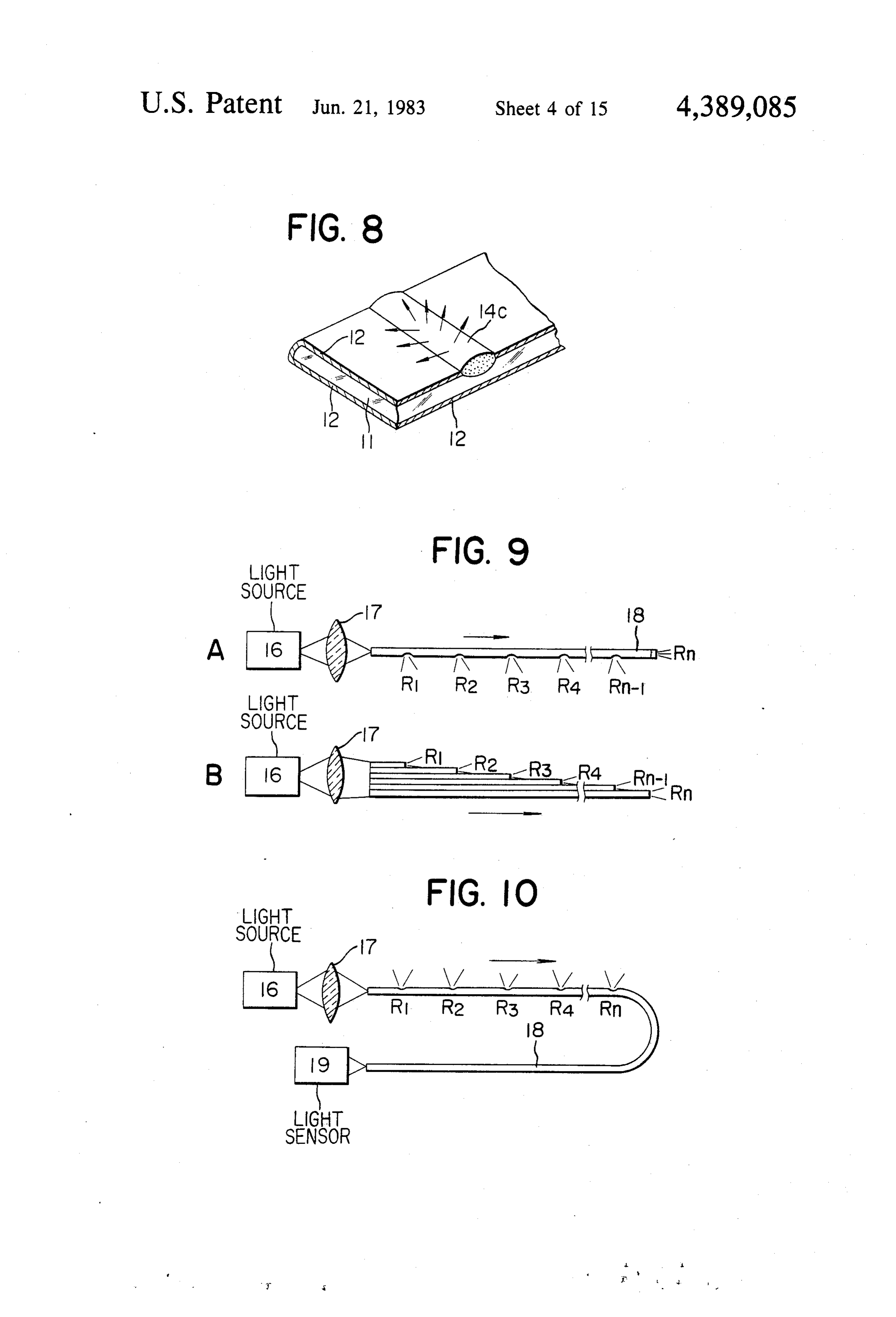
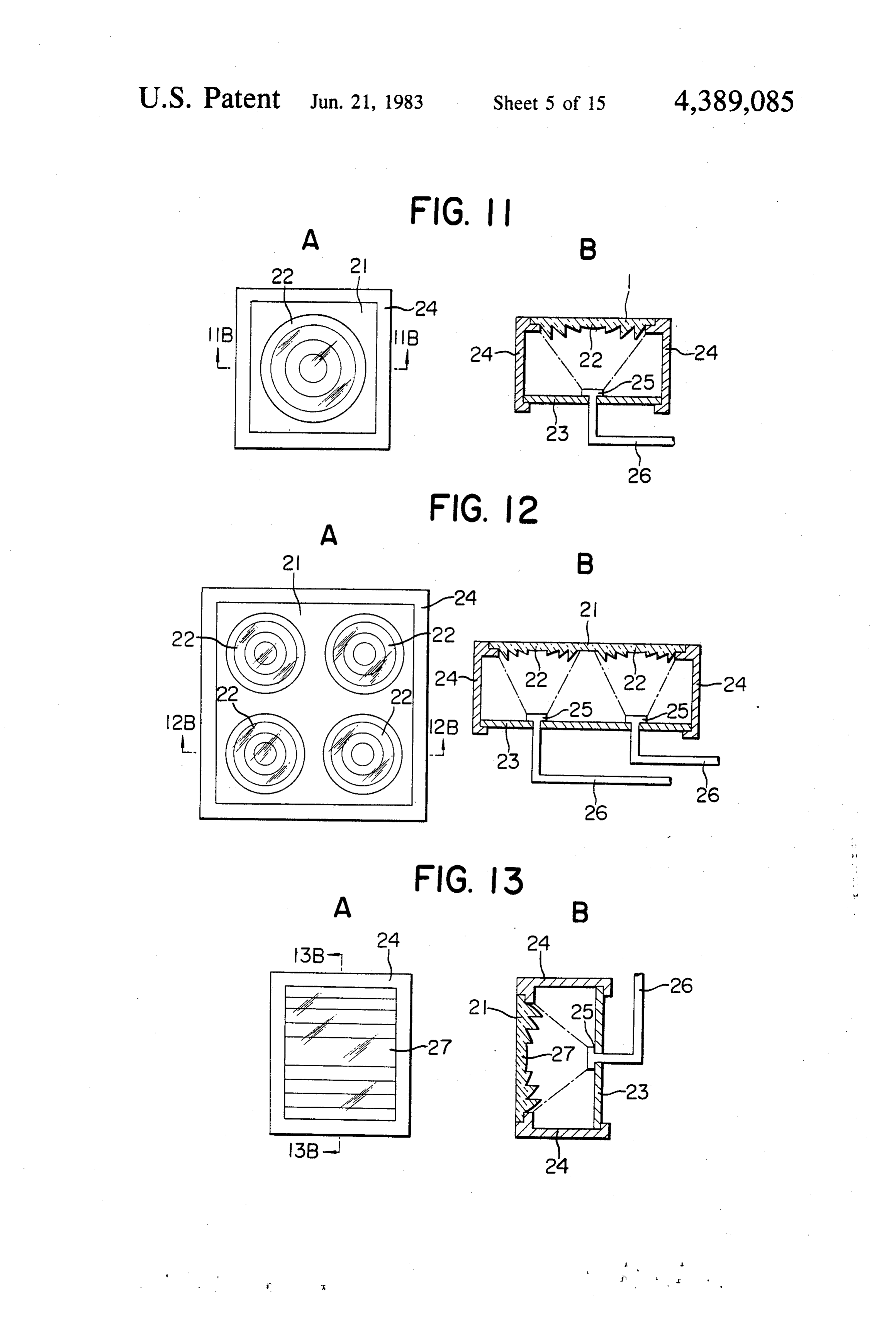
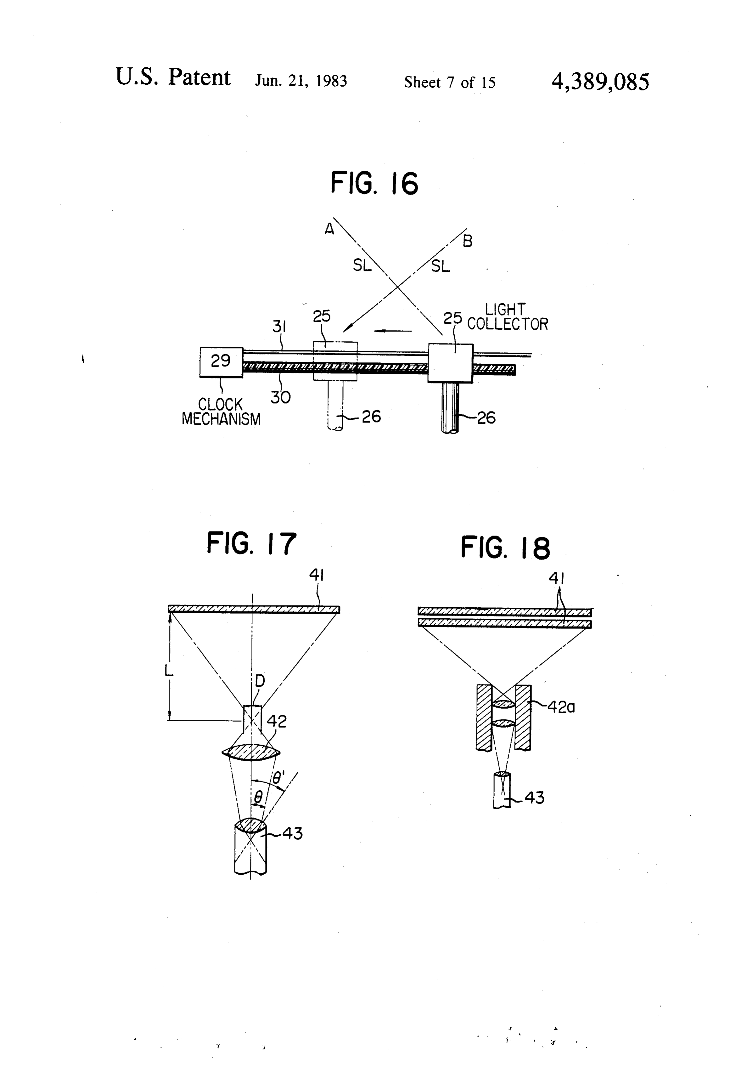
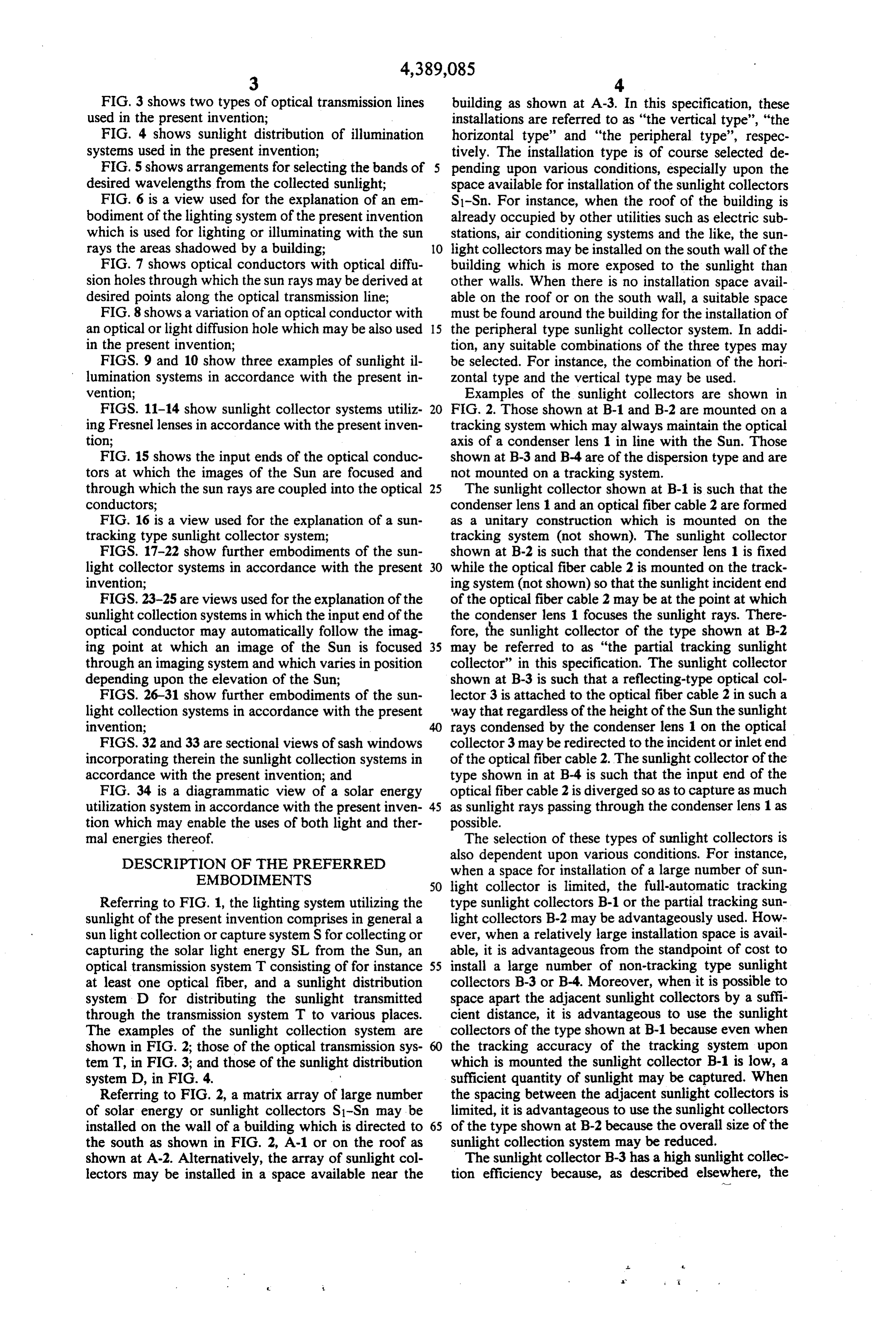
FIG. 3 shows two types of optical transmission lines building as shown at A-3. In this specification, these used in the present invention; installations are referred to as "the vertical type', “the FIG. 4 shows sunlight distribution of illumination horizontal type" and "the peripheral type", respec systems used in the present invention; tively. The installation type is of course selected de FIG. 5 shows arrangements for selecting the bands of 5 pending upon various conditions, especially upon the desired wavelengths from the collected sunlight; space available for installation of the sunlight collectors FIG. 6 is a view used for the explanation of an em S1-Sn. For instance, when the roof of the building is bodiment of the lighting system of the present invention already occupied by other utilities such as electric sub which is used for lighting or illuminating with the sun stations, air conditioning systems and the like, the sun rays the areas shadowed by a building; O light collectors may be installed on the south wall of the FIG. 7 shows optical conductors with optical diffu building which is more exposed to the sunlight than sion holes through which the sun rays may be derived at other walls. When there is no installation space avail desired points along the optical transmission line; able on the roof or on the south wall, a suitable space FIG. 8 shows a variation of an optical conductor with must be found around the building for the installation of an optical or light diffusion hole which may be also used 15 the peripheral type sunlight collector system. In addi in the present invention; tion, any suitable combinations of the three types may FIGS. 9 and 10 show three examples of sunlight il be selected. For instance, the combination of the hori lumination systems in accordance with the present in Zontal type and the vertical type may be used. vention; Examples of the sunlight collectors are shown in FIGS. 11-14 show sunlight collector systems utiliz 20 FIG. 2. Those shown at B-1 and B-2 are mounted on a ing Fresnel lenses in accordance with the present inven tracking system which may always maintain the optical tion; axis of a condenser lens 1 in line with the Sun. Those FIG. 15 shows the input ends of the optical conduc shown at B-3 and B-4 are of the dispersion type and are tors at which the images of the Sun are focused and not mounted on a tracking system.
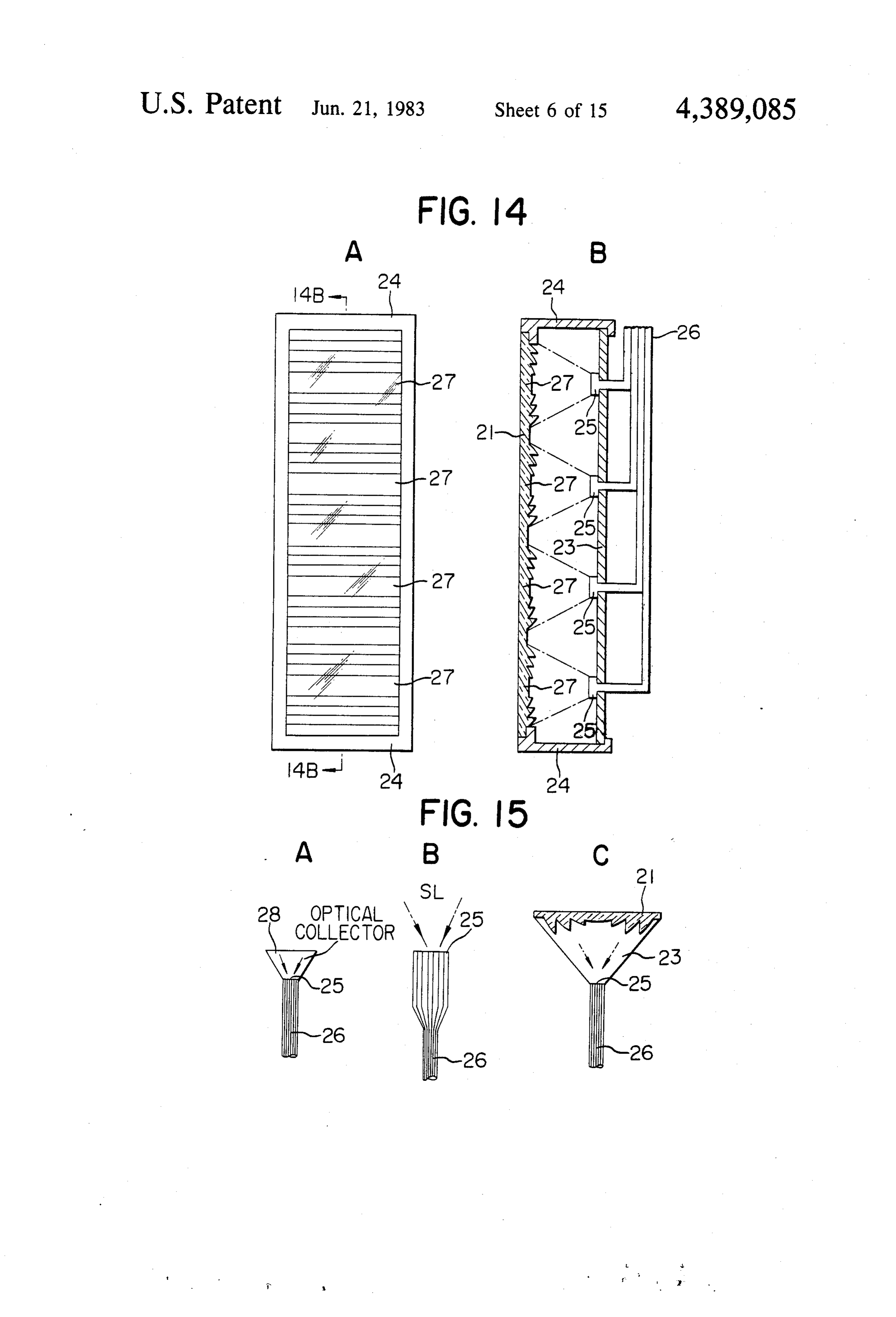
through which the sun rays are coupled into the optical 25 The sunlight collector shown at B-1 is such that the conductors; condenser lens 1 and an optical fiber cable 2 are formed FIG. 16 is a view used for the explanation of a sun as a unitary construction which is mounted on the tracking type sunlight collector system; tracking system (not shown). The sunlight collector FIGS. 17-22 show further embodiments of the sun shown at B-2 is such that the condenser lens 1 is fixed light collector systems in accordance with the present 30 while the optical fiber cable 2 is mounted on the track invention; ing system (not shown) so that the sunlight incident end FIGS. 23-25 are views used for the explanation of the of the optical fiber cable 2 may be at the point at which sunlight collection systems in which the input end of the the condenser lens 1 focuses the sunlight rays. There optical conductor may automatically follow the imag fore, the sunlight collector of the type shown at B-2 ing point at which an image of the Sun is focused 35 may be referred to as "the partial tracking sunlight through an imaging system and which varies in position collector' in this specification. The sunlight collector depending upon the elevation of the Sun; shown at B-3 is such that a reflecting-type optical col FIGS. 26-31 show further embodiments of the sun lector 3 is attached to the optical fiber cable 2 in such a light collection systems in accordance with the present way that regardless of the height of the Sun the sunlight invention; rays condensed by the condenser lens 1 on the optical FIGS. 32 and 33 are sectional views of sash windows collector 3 may be redirected to the incident or inlet end incorporating therein the sunlight collection systems in of the optical fiber cable 2. The sunlight collector of the accordance with the present invention; and type shown in at B-4 is such that the input end of the FIG. 34 is a diagrammatic view of a solar energy optical fiber cable 2 is diverged so as to capture as much utilization system in accordance with the present inven 45 as sunlight rays passing through the condenser lens 1 as tion which may enable the uses of both light and ther possible.
mal energies thereof. The selection of these types of sunlight collectors is DESCRIPTION OF THE PREFERRED also dependent upon various conditions. For instance, EMBODIMENTS when a space for installation of a large number of Sun 50 light collector is limited, the full-automatic tracking
Referring to FIG. 1, the lighting system utilizing the type sunlight collectors B-1 or the partial tracking sun sunlight of the present invention comprises in general a light collectors B-2 may be advantageously used. How sunlight collection or capture system S for collecting or ever, when a relatively large installation space is avail capturing the solar light energy SL from the Sun, an able, it is advantageous from the standpoint of cost to optical transmission system T consisting of for instance 55 install a large number of non-tracking type sunlight at least one optical fiber, and a sunlight distribution collectors B-3 or B-4. Moreover, when it is possible to system D for distributing the sunlight transmitted space apart the adjacent sunlight collectors by a suffi through the transmission system T to various places. cient distance, it is advantageous to use the sunlight The examples of the sunlight collection system are collectors of the type shown at B-1 because even when shown in FIG. 2; those of the optical transmission sys the tracking accuracy of the tracking system upon tem. T, in FIG. 3; and those of the sunlight distribution which is mounted the sunlight collector B-1 is low, a system D, in FIG. 4. sufficient quantity of sunlight may be captured. When Referring to FIG. 2, a matrix array of large number the spacing between the adjacent sunlight collectors is of solar energy or sunlight collectors S1-Sn may be limited, it is advantageous to use the sunlight collectors installed on the wall of a building which is directed to 65 of the type shown at B-2 because the overall size of the the south as shown in FIG. 2, A-1 or on the roof as sunlight collection system may be reduced. shown at A-2. Alternatively, the array of sunlight col The sunlight collector B-3 has a high sunlight collec lectors may be installed in a space available near the tion efficiency because, as described elsewhere, the
Page 19
optical deflector 3 redirects the sunlight rays incident The input splitting type shown at A is advantageous thereon to the input end of the optical fiber cable 2. In over the output splitting type B in that it becomes possi addition, because of its small size and installation space, ble to use the optical fiber cables 2 which exhibit the the sunlight collection system may be reduced in overall least propagation losses to the light of different wave size. The sunlight collector B-4 is advantageous in that 5. lengths. As a result, a high transmission efficiency may its production cost is less and its reliability is high be be obtained.
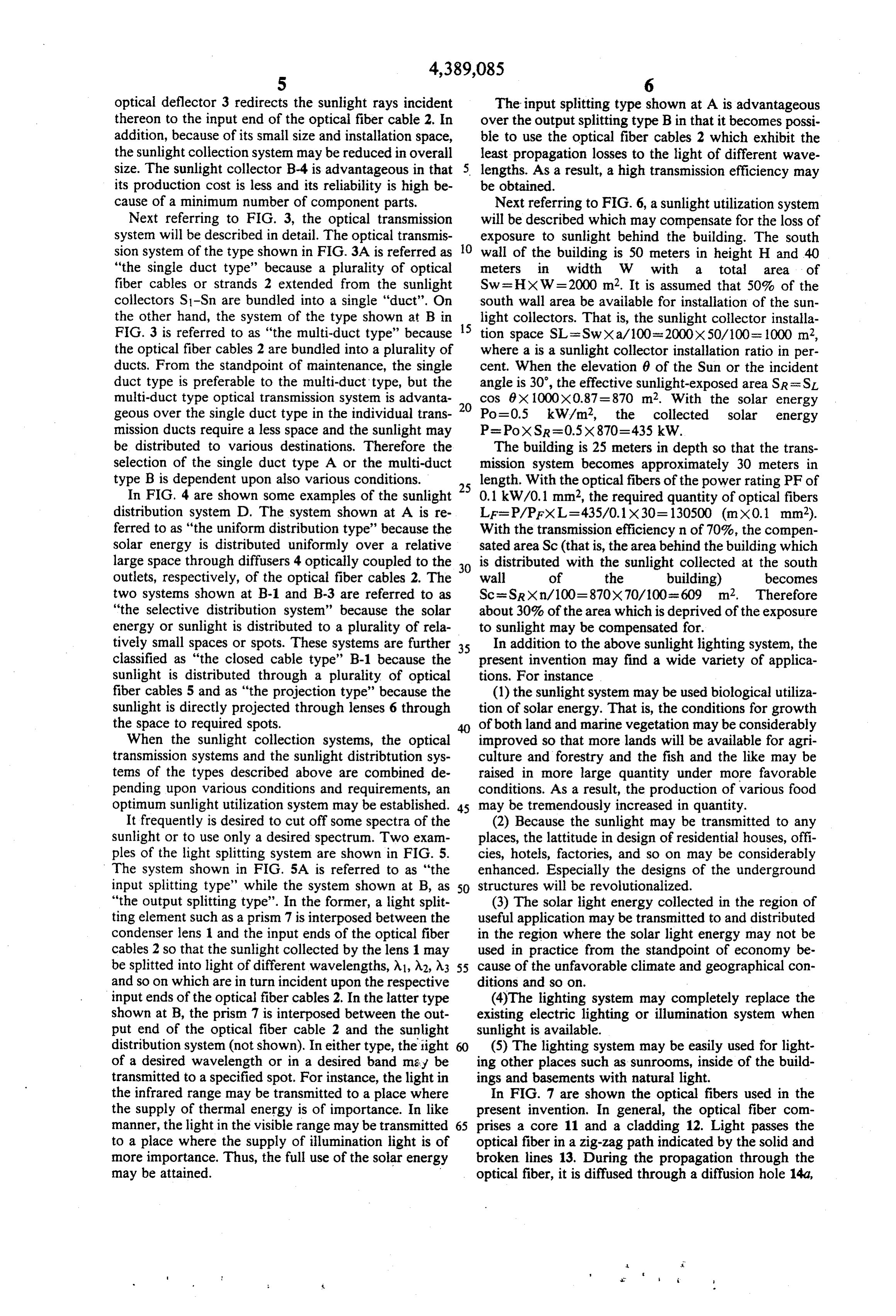
cause of a minimum number of component parts. Next referring to FIG. 6, a sunlight utilization system Next referring to FIG. 3, the optical transmission will be described which may compensate for the loss of system will be described in detail. The optical transmis exposure to sunlight behind the building. The south sion system of the type shown in FIG. 3A is referred as 10 wall of the building is 50 meters in height H and 40 "the single duct type' because a plurality of optical meters in width W with a total area of fiber cables or strands 2 extended from the sunlight Sw= HXW = 2000 m2. It is assumed that 50% of the collectors S1-Sn are bundled into a single "duct". On south wall area be available for installation of the sun the other hand, the system of the type shown at B in 15 light collectors. That is, the sunlight collector installa FIG. 3 is referred to as "the multi-duct type' because tion space SL =Swxa/100=2000x50/100 = 1000 m2, the optical fiber cables 2 are bundled into a plurality of where a is a sunlight collector installation ratio in per ducts. From the standpoint of maintenance, the single cent. When the elevation 6 of the Sun or the incident duct type is preferable to the multi-duct type, but the angle is 30, the effective sunlight-exposed area SR = SL multi-duct type optical transmission system is advanta cos 0x 1000x0.87=870 m2. With the solar energy geous over the single duct type in the individual trans 20 Po-0.5 kW/m2, the collected solar energy mission ducts require a less space and the sunlight may P= PoxSR =0.5x870=435 kW.
be distributed to various destinations. Therefore the The building is 25 meters in depth so that the trans selection of the single duct type A or the multi-duct mission system becomes approximately 30 meters in type B is dependent upon also various conditions. length. With the optical fibers of the power rating PF of In FIG. 4 are shown some examples of the sunlight 25 0.1 kW/0.1 mm2, the required quantity of optical fibers distribution system D. The system shown at A is re LF=P/PFXL=435/0.1x30=130500 (mx0.1 mm2). ferred to as "the uniform distribution type' because the With the transmission efficiency in of 70%, the compen solar energy is distributed uniformly over a relative sated area Sc (that is, the area behind the building which large space through diffusers 4 optically coupled to the 30 is distributed with the sunlight collected at the south outlets, respectively, of the optical fiber cables 2. The wall of the building) becomes two systems shown at B-1 and B-3 are referred to as Sc=SRXn/100=870X70/100=609 m2. Therefore "the selective distribution system' because the solar about 30% of the area which is deprived of the exposure energy or sunlight is distributed to a plurality of rela to sunlight may be compensated for. tively small spaces or spots. These systems are further 35 In addition to the above sunlight lighting system, the classified as "the closed cable type' B-1 because the present invention may find a wide variety of applica sunlight is distributed through a plurality of optical tions. For instance fiber cables 5 and as "the projection type' because the (1) the sunlight system may be used biological utiliza sunlight is directly projected through lenses 6 through tion of solar energy. That is, the conditions for growth the space to required spots. 40 of both land and marine vegetation may be considerably When the sunlight collection systems, the optical improved so that more lands will be available for agri transmission systems and the sunlight distribtution sys culture and forestry and the fish and the like may be tems of the types described above are combined de raised in more large quantity under more favorable pending upon various conditions and requirements, an conditions. As a result, the production of various food optimum sunlight utilization system may be established. 45 may be tremendously increased in quantity. It frequently is desired to cut off some spectra of the (2) Because the sunlight may be transmitted to any sunlight or to use only a desired spectrum. Two exam places, the lattitude in design of residential houses, offi ples of the light splitting system are shown in FIG. 5. cies, hotels, factories, and so on may be considerably The system shown in FIG. 5A is referred to as "the enhanced. Especially the designs of the underground input splitting type' while the system shown at B, as SO structures will be revolutionalized. "the output splitting type'. In the former, a light split (3) The solar light energy collected in the region of ting element such as a prism 7 is interposed between the useful application may be transmitted to and distributed condenser lens 1 and the input ends of the optical fiber in the region where the solar light energy may not be cables 2 so that the sunlight collected by the lens 1 may used in practice from the standpoint of economy be be splitted into light of different wavelengths, A1, A2, A3 55 cause of the unfavorable climate and geographical con and so on which are in turn incident upon the respective ditions and so on.
input ends of the optical fiber cables 2. In the latter type (4)The lighting system may completely replace the shown at B, the prism 7 is interposed between the out existing electric lighting or illumination system when put end of the optical fiber cable 2 and the sunlight sunlight is available.
distribution system (not shown). In either type, the tight (5) The lighting system may be easily used for light of a desired wavelength or in a desired band may be ing other places such as sunrooms, inside of the build transmitted to a specified spot. For instance, the light in ings and basements with natural light. the infrared range may be transmitted to a place where In FIG. 7 are shown the optical fibers used in the the supply of thermal energy is of importance. In like present invention. In general, the optical fiber com manner, the light in the visible range may be transmitted 65 prises a core 11 and a cladding 12. Light passes the to a place where the supply of illumination light is of optical fiber in a zig-zag path indicated by the solid and more importance. Thus, the full use of the solar energy broken lines 13. During the propagation through the may be attained. optical fiber, it is diffused through a diffusion hole 14a,
Page 20
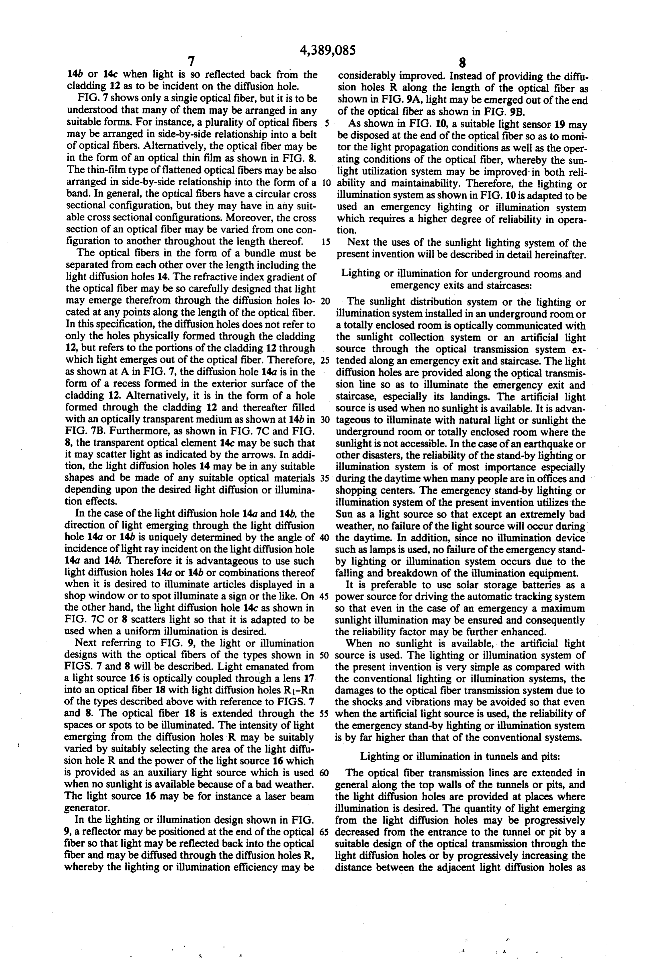
14b or 14c when light is so reflected back from the considerably improved. Instead of providing the diffu cladding 12 as to be incident on the diffusion hole. sion holes R along the length of the optical fiber as FIG. 7 shows only a single optical fiber, but it is to be shown in FIG. 9A, light may be emerged out of the end understood that many of them may be arranged in any of the optical fiber as shown in FIG.9B. suitable forms. For instance, a plurality of optical fibers As shown in FIG. 10, a suitable light sensor 19 may may be arranged in side-by-side relationship into a belt be disposed at the end of the optical fiber so as to moni of optical fibers. Alternatively, the optical fiber may be tor the light propagation conditions as well as the oper in the form of an optical thin film as shown in FIG. 8. ating conditions of the optical fiber, whereby the sun The thin-film type of flattened optical fibers may be also light utilization system may be improved in both reli arranged in side-by-side relationship into the form of a 10 ability and maintainability. Therefore, the lighting or band. In general, the optical fibers have a circular cross illumination system as shown in FIG. 10 is adapted to be sectional configuration, but they may have in any suit used an emergency lighting or illumination system able cross sectional configurations. Moreover, the cross which requires a higher degree of reliability in opera section of an optical fiber may be varied from one con tion.
figuration to another throughout the length thereof. 5 Next the uses of the sunlight lighting system of the The optical fibers in the form of a bundle must be present invention will be described in detail hereinafter. separated from each other over the length including the light diffusion holes 14. The refractive index gradient of Lighting or illumination for underground rooms and the optical fiber may be so carefully designed that light emergency exits and staircases: may emerge therefrom through the diffusion holes lo 20 The sunlight distribution system or the lighting or cated at any points along the length of the optical fiber. illumination system installed in an underground room or In this specification, the diffusion holes does not refer to a totally enclosed room is optically communicated with only the holes physically formed through the cladding the sunlight collection system or an artificial light 12, but refers to the portions of the cladding 12 through source through the optical transmission system ex which light emerges out of the optical fiber. Therefore, 25 tended along an emergency exit and staircase. The light as shown at A in FIG. 7, the diffusion hole 14a is in the diffusion holes are provided along the optical transmis form of a recess formed in the exterior surface of the sion line so as to illuminate the emergency exit and cladding 12. Alternatively, it is in the form of a hole staircase, especially its landings. The artificial light formed through the cladding 12 and thereafter filled source is used when no sunlight is available. It is advan with an optically transparent medium as shown at 14b in 30 tageous to illuminate with natural light or sunlight the FIG. 7B. Furthermore, as shown in FIG. 7C and FIG. underground room or totally enclosed room where the 8, the transparent optical element 14c may be such that sunlight is not accessible. In the case of an earthquake or it may scatter light as indicated by the arrows. In addi other disasters, the reliability of the stand-by lighting or tion, the light diffusion holes 14 may be in any suitable illumination system is of most importance especially shapes and be made of any suitable optical materials 35 during the daytime when many people are in offices and depending upon the desired light diffusion or illumina shopping centers. The emergency stand-by lighting or tion effects. illumination system of the present invention utilizes the In the case of the light diffusion hole 14a and 14b, the Sun as a light source so that except an extremely bad direction of light emerging through the light diffusion weather, no failure of the light source will occur during hole 14a or 14b is uniquely determined by the angle of 40 the daytime. In addition, since no illumination device incidence of light ray incident on the light diffusion hole such as lamps is used, no failure of the emergency stand 14a and 14b. Therefore it is advantageous to use such by lighting or illumination system occurs due to the light diffusion holes 14a or 14b or combinations thereof falling and breakdown of the illumination equipment. when it is desired to illuminate articles displayed in a It is preferable to use solar storage batteries as a shop window or to spot illuminate a sign or the like. On 45 power source for driving the automatic tracking system the other hand, the light diffusion hole 14c as shown in so that even in the case of an emergency a maximum FIG. 7C or 8 scatters light so that it is adapted to be sunlight illumination may be ensured and consequently used when a uniform illumination is desired. the reliability factor may be further enhanced. Next referring to FIG. 9, the light or illumination When no sunlight is available, the artificial light designs with the optical fibers of the types shown in 50 source is used. The lighting or illumination system of FIGS. 7 and 8 will be described. Light emanated from the present invention is very simple as compared with a light source 16 is optically coupled through a lens 17 the conventional lighting or illumination systems, the into an optical fiber 18 with light diffusion holes R-Rn damages to the optical fiber transmission system due to of the types described above with reference to FIGS. 7 the shocks and vibrations may be avoided so that even and 8. The optical fiber 18 is extended through the 55 when the artificial light source is used, the reliability of spaces or spots to be illuminated. The intensity of light the emergency stand-by lighting or illumination system emerging from the diffusion holes R may be suitably is by far higher than that of the conventional systems. varied by suitably selecting the area of the light diffu sion hole R and the power of the light source 16 which Lighting or illumination in tunnels and pits: is provided as an auxiliary light source which is used The optical fiber transmission lines are extended in when no sunlight is available because of a bad weather. general along the top walls of the tunnels or pits, and The light source 16 may be for instance a laser beam the light diffusion holes are provided at places where generator. illumination is desired. The quantity of light emerging In the lighting or illumination design shown in FIG. from the light diffusion holes may be progressively 9, a reflector may be positioned at the end of the optical decreased from the entrance to the tunnel or pit by a fiber so that light may be reflected back into the optical suitable design of the optical transmission through the fiber and may be diffused through the diffusion holes R, light diffusion holes or by progressively increasing the whereby the lighting or illumination efficiency may be distance between the adjacent light diffusion holes as
Page 21
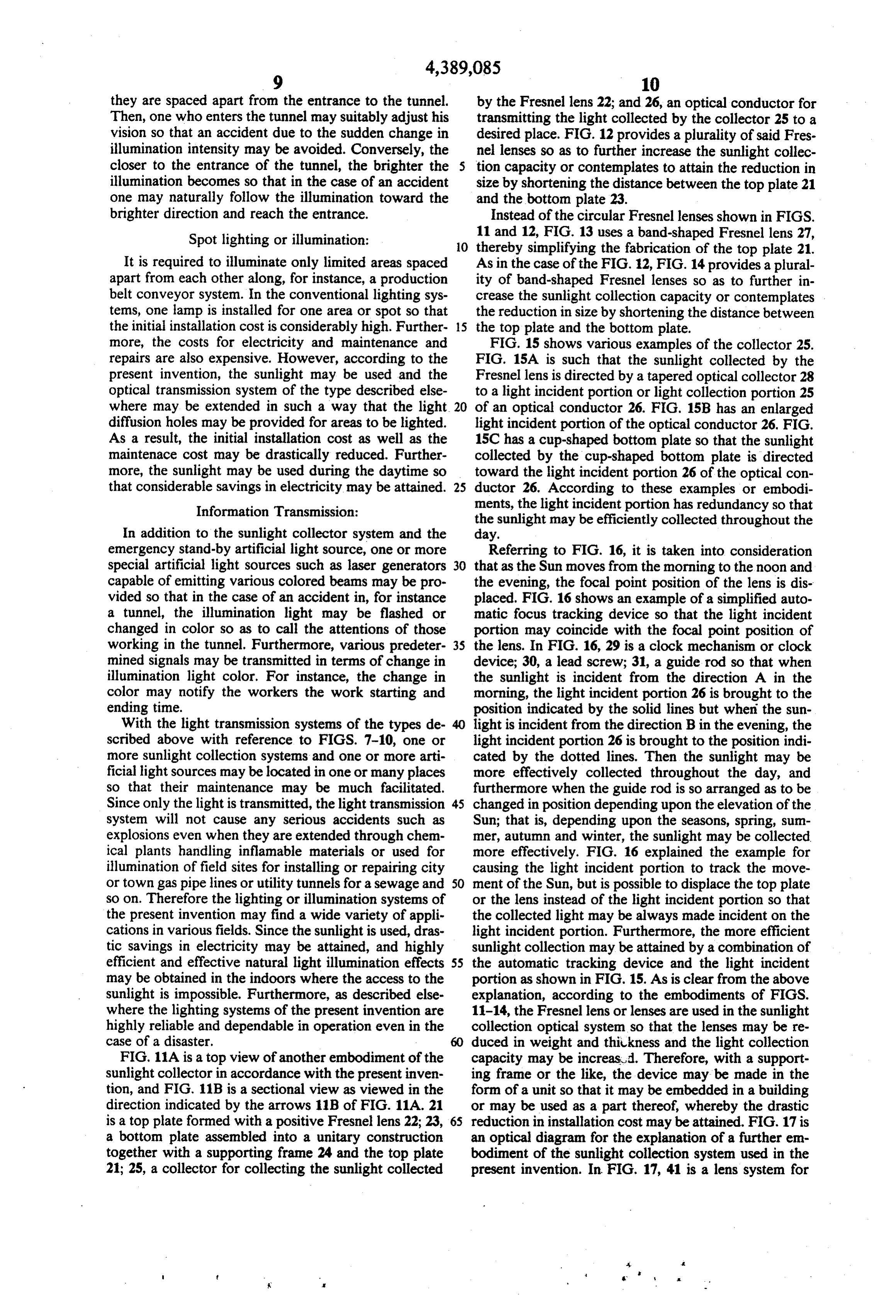
they are spaced apart from the entrance to the tunnel. by the Fresnel lens 22; and 26, an optical conductor for Then, one who enters the tunnel may suitably adjust his transmitting the light collected by the collector 25 to a vision so that an accident due to the sudden change in desired place. FIG. 12 provides a plurality of said Fres illumination intensity may be avoided. Conversely, the nel lenses so as to further increase the sunlight collec closer to the entrance of the tunnel, the brighter the 5 tion capacity or contemplates to attain the reduction in illumination becomes so that in the case of an accident size by shortening the distance between the top plate 21 one may naturally follow the illumination toward the and the bottom plate 23.
brighter direction and reach the entrance. Instead of the circular Fresnel lenses shown in FIGS. Spot lighting or illumination: 11 and 12, FIG. 13 uses a band-shaped Fresnel lens 27, 10 thereby simplifying the fabrication of the top plate 21.
It is required to illuminate only limited areas spaced As in the case of the FIG. 12, FIG. 14 provides a plural apart from each other along, for instance, a production ity of band-shaped Fresnel lenses so as to further in belt conveyor system. In the conventional lighting sys crease the sunlight collection capacity or contemplates tems, one lamp is installed for one area or spot so that the reduction in size by shortening the distance between the initial installation cost is considerably high. Further 15 the top plate and the bottom plate. more, the costs for electricity and maintenance and FIG. 15 shows various examples of the collector 25. repairs are also expensive. However, according to the FIG. 15A is such that the sunlight collected by the present invention, the sunlight may be used and the Fresnel lens is directed by a tapered optical collector 28 optical transmission system of the type described else to a light incident portion or light collection portion 25 where may be extended in such a way that the light. 20 of an optical conductor 26. FIG. 15B has an enlarged diffusion holes may be provided for areas to be lighted. light incident portion of the optical conductor 26. FIG. As a result, the initial installation cost as well as the 15C has a cup-shaped bottom plate so that the sunlight maintenace cost may be drastically reduced. Further collected by the cup-shaped bottom plate is directed more, the sunlight may be used during the daytime so toward the light incident portion 26 of the optical con that considerable savings in electricity may be attained. 25 ductor 26. According to these examples or embodi Information Transmission: ments, the light incident portion has redundancy so that the sunlight may be efficiently collected throughout the
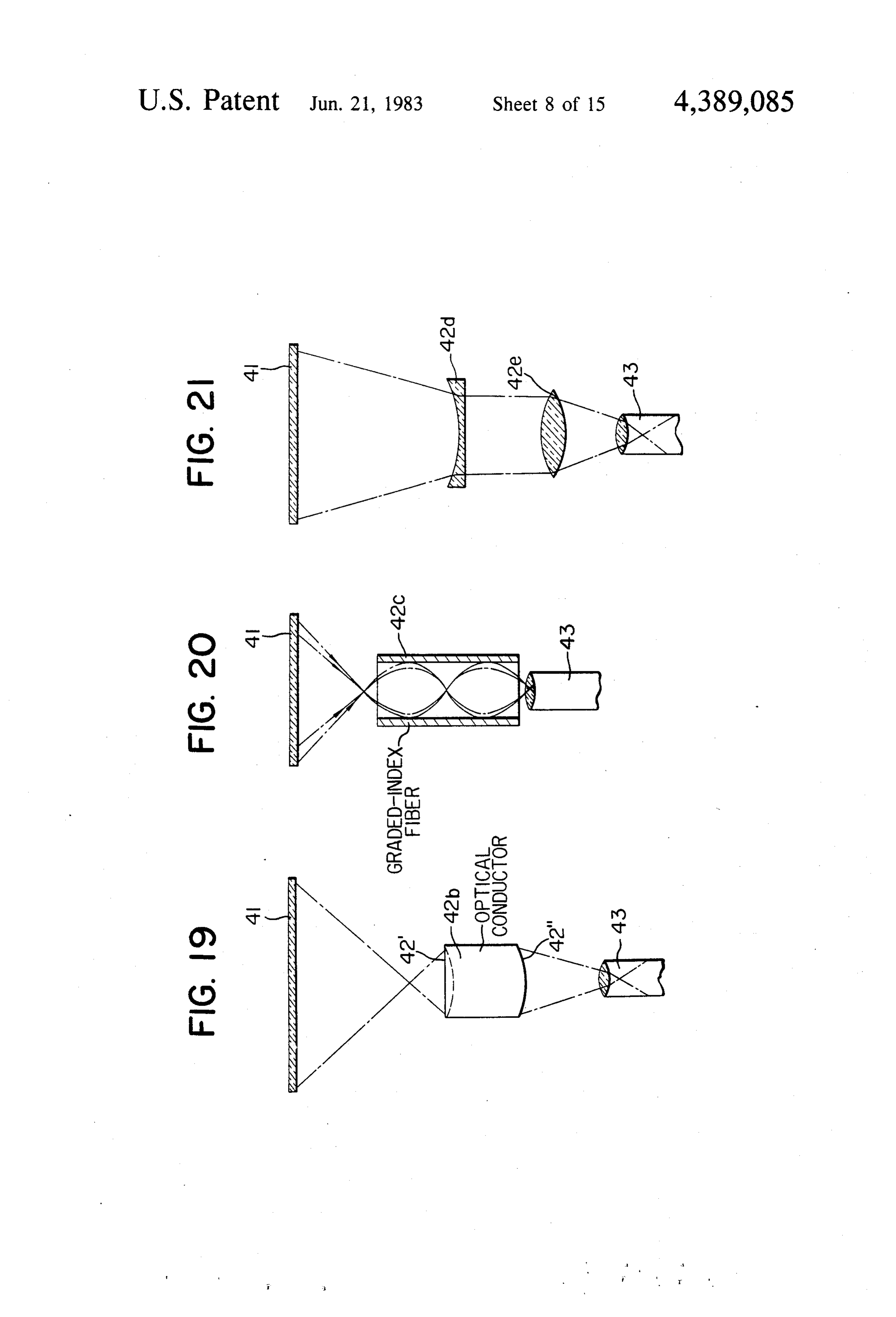
In addition to the sunlight collector system and the day, emergency stand-by artificial light source, one or more Referring to FIG. 16, it is taken into consideration special artificial light sources such as laser generators 30 that as the Sun moves from the morning to the noon and capable of emitting various colored beams may be pro the evening, the focal point position of the lens is dis vided so that in the case of an accident in, for instance placed. FIG. 16 shows an example of a simplified auto a tunnel, the illumination light may be flashed or matic focus tracking device so that the light incident changed in color so as to call the attentions of those portion may coincide with the focal point position of working in the tunnel. Furthermore, various predeter 35 the lens. In FIG. 16, 29 is a clock mechanism or clock mined signals may be transmitted in terms of change in device; 30, a lead screw; 31, a guide rod so that when illumination light color. For instance, the change in the sunlight is incident from the direction A in the color may notify the workers the work starting and morning, the light incident portion 26 is brought to the ending time. position indicated by the solid lines but when the sun With the light transmission systems of the types de 40 light is incident from the direction B in the evening, the scribed above with reference to FIGS. 7-10, one or light incident portion 26 is brought to the position indi more sunlight collection systems and one or more arti cated by the dotted lines. Then the sunlight may be ficial light sources may be located in one or many places more effectively collected throughout the day, and so that their maintenance may be much facilitated. furthermore when the guide rod is so arranged as to be Since only the light is transmitted, the light transmission 45 changed in position depending upon the elevation of the system will not cause any serious accidents such as Sun; that is, depending upon the seasons, spring, sum explosions even when they are extended through chem mer, autumn and winter, the sunlight may be collected ical plants handling inflamable materials or used for more effectively. FIG. 16 explained the example for illumination of field sites for installing or repairing city causing the light incident portion to track the move or town gas pipelines or utility tunnels for a sewage and 50 ment of the Sun, but is possible to displace the top plate so on. Therefore the lighting or illumination systems of or the lens instead of the light incident portion so that the present invention may find a wide variety of appli the collected light may be always made incident on the cations in various fields. Since the sunlight is used, dras light incident portion. Furthermore, the more efficient tic savings in electricity may be attained, and highly sunlight collection may be attained by a combination of efficient and effective natural light illumination effects 55 the automatic tracking device and the light incident may be obtained in the indoors where the access to the portion as shown in FIG. 15. As is clear from the above sunlight is impossible. Furthermore, as described else explanation, according to the embodiments of FIGS. where the lighting systems of the present invention are 11-14, the Fresnel lens or lenses are used in the sunlight highly reliable and dependable in operation even in the collection optical system so that the lenses may be re case of a disaster. duced in weight and thiukness and the light collection FIG. 11A is a top view of another embodiment of the capacity may be increasud. Therefore, with a support sunlight collector in accordance with the present inven ing frame or the like, the device may be made in the tion, and FIG. 11B is a sectional view as viewed in the form of a unit so that it may be embedded in a building direction indicated by the arrows 11B of FIG. 11A. 21 or may be used as a part thereof, whereby the drastic is a top plate formed with a positive Fresnel lens 22; 23, 65 reduction in installation cost may be attained. FIG. 17 is a bottom plate assembled into a unitary construction an optical diagram for the explanation of a further em together with a supporting frame 24 and the top plate bodiment of the sunlight collection system used in the 21; 25, a collector for collecting the sunlight collected present invention. In FIG. 17, 41 is a lens system for
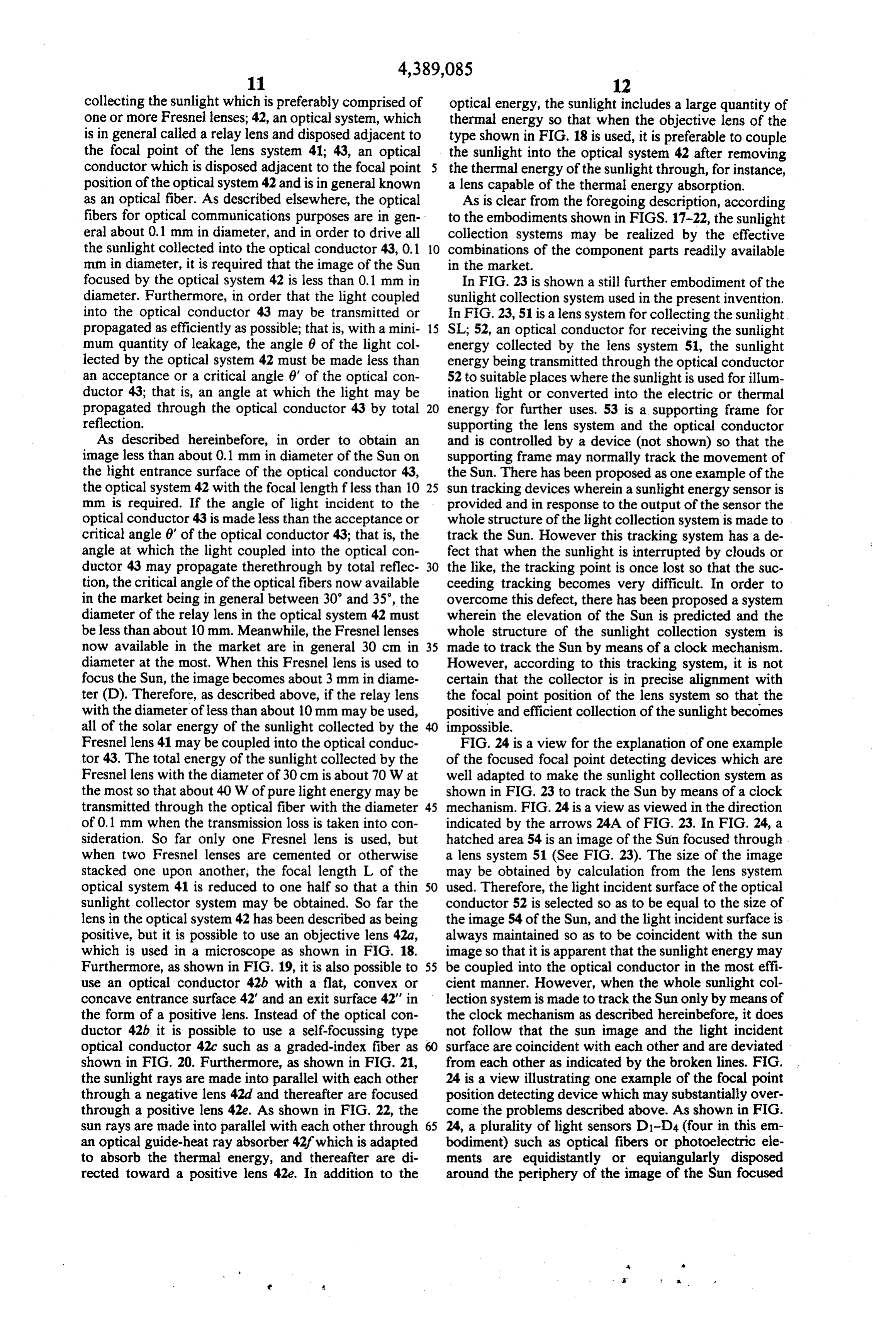
Page 22
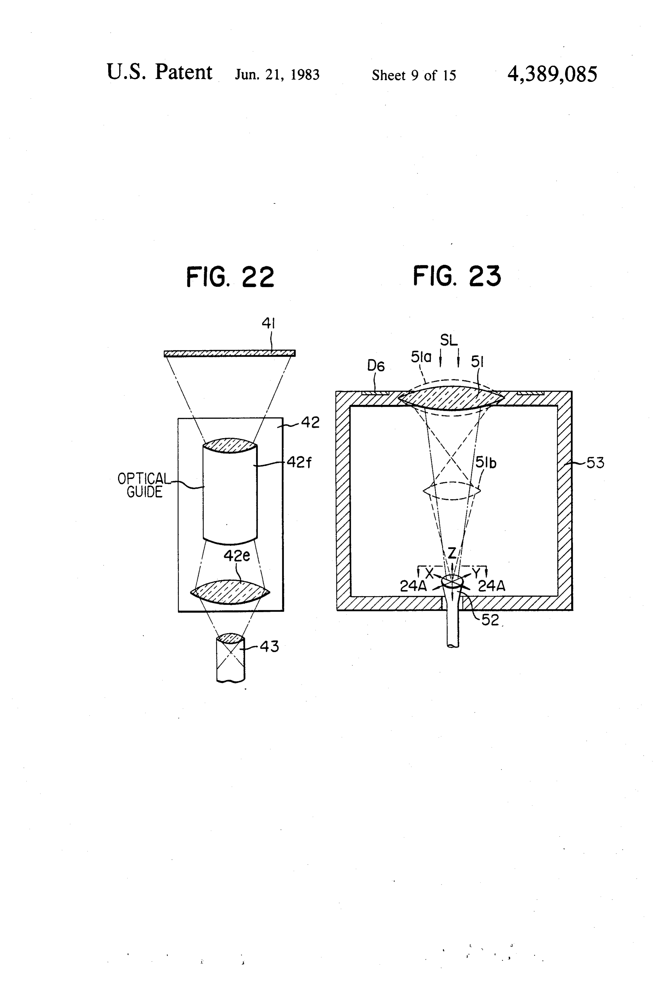
collecting the sunlight which is preferably comprised of optical energy, the sunlight includes a large quantity of one or more Fresnel lenses; 42, an optical system, which thermal energy so that when the objective lens of the is in general called a relay lens and disposed adjacent to type shown in FIG. 18 is used, it is preferable to couple the focal point of the lens system 41; 43, an optical the sunlight into the optical system 42 after removing conductor which is disposed adjacent to the focal point the thermal energy of the sunlight through, for instance, position of the optical system 42 and is in general known a lens capable of the thermal energy absorption. as an optical fiber. As described elsewhere, the optical As is clear from the foregoing description, according fibers for optical communications purposes are in gen to the embodiments shown in FIGS. 17-22, the sunlight eral about 0.1 mm in diameter, and in order to drive all collection systems may be realized by the effective the sunlight collected into the optical conductor 43, 0.1 O combinations of the component parts readily available mm in diameter, it is required that the image of the Sun in the market.
focused by the optical system 42 is less than 0.1 mm in In FIG. 23 is shown a still further embodiment of the diameter. Furthermore, in order that the light coupled Sunlight collection system used in the present invention. into the optical conductor 43 may be transmitted or In FIG. 23, 51 is a lens system for collecting the sunlight propagated as efficiently as possible; that is, with a mini 15 SL, 52, an optical conductor for receiving the sunlight mum quantity of leakage, the angle 6 of the light col energy collected by the lens system 51, the sunlight lected by the optical system 42 must be made less than energy being transmitted through the optical conductor an acceptance or a critical angle 6' of the optical con 52 to suitable places where the sunlight is used for illum ductor 43; that is, an angle at which the light may be ination light or converted into the electric or thermal propagated through the optical conductor 43 by total energy for further uses. 53 is a supporting frame for reflection, supporting the lens system and the optical conductor As described hereinbefore, in order to obtain an and is controlled by a device (not shown) so that the image less than about 0.1 mm in diameter of the Sun on supporting frame may normally track the movement of the light entrance surface of the optical conductor 43, the Sun. There has been proposed as one example of the the optical system 42 with the focal length fless than 10 25 Sun tracking devices wherein a sunlight energy sensor is mm is required. If the angle of light incident to the provided and in response to the output of the sensor the optical conductor 43 is made less than the acceptance or whole structure of the light collection system is made to critical angle 6' of the optical conductor 43; that is, the track the Sun. However this tracking system has a de angle at which the light coupled into the optical con fect that when the sunlight is interrupted by clouds or ductor 43 may propagate therethrough by total reflec 30 the like, the tracking point is once lost so that the suc tion, the critical angle of the optical fibers now available ceeding tracking becomes very difficult. In order to in the market being in general between 30' and 35, the overcome this defect, there has been proposed a system diameter of the relay lens in the optical system 42 must wherein the elevation of the Sun is predicted and the be less than about 10 mm. Meanwhile, the Fresnel lenses whole structure of the sunlight collection system is now available in the market are in general 30 cm in 35 made to track the Sun by means of a clock mechanism. diameter at the most. When this Fresnel lens is used to However, according to this tracking system, it is not focus the Sun, the image becomes about 3 mm in diame certain that the collector is in precise alignment with ter (D). Therefore, as described above, if the relay lens the focal point position of the lens system so that the with the diameter of less than about 10 mm may be used, positive and efficient collection of the sunlight becomes all of the solar energy of the sunlight collected by the impossible.
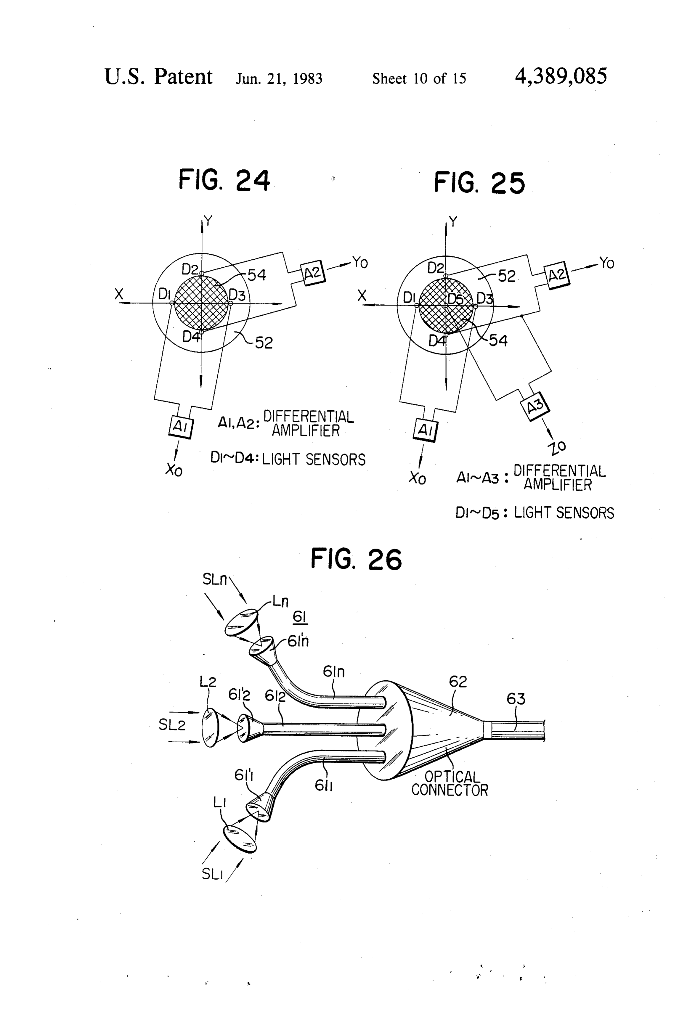
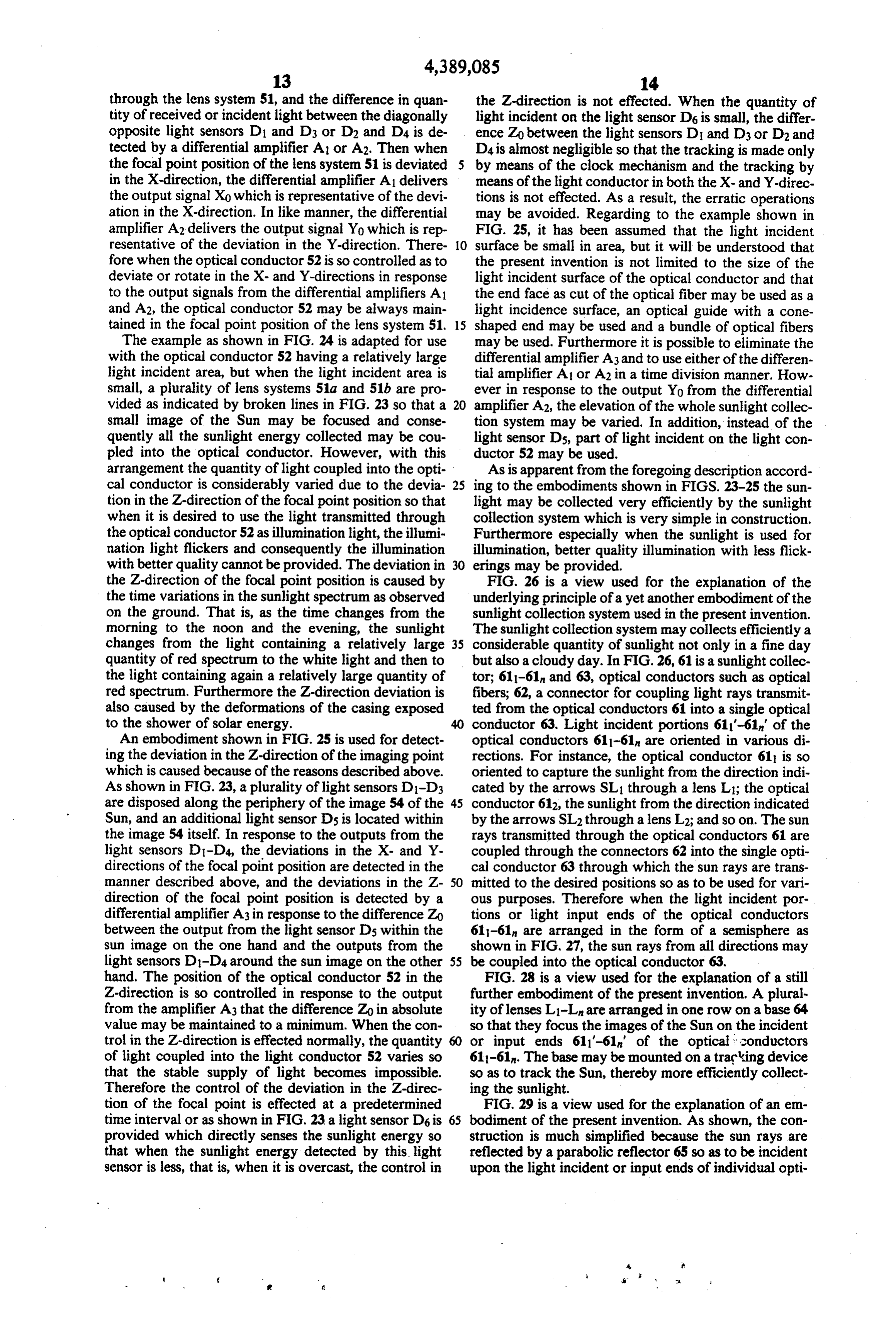
Fresnel lens 41 may be coupled into the optical conduc FIG. 24 is a view for the explanation of one example tor 43. The total energy of the sunlight collected by the of the focused focal point detecting devices which are Fresnel lens with the diameter of 30 cm is about 70 W at well adapted to make the sunlight collection system as the most so that about 40W of pure light energy may be shown in FIG. 23 to track the Sun by means of a clock transmitted through the optical fiber with the diameter 45 mechanism. FIG. 24 is a view as viewed in the direction of 0.1 mm when the transmission loss is taken into con indicated by the arrows 24A of FIG. 23. In FIG. 24, a sideration. So far only one Fresnel lens is used, but hatched area 54 is an image of the Sun focused through when two Fresnel lenses are cemented or otherwise a lens system 51 (See FIG. 23). The size of the image stacked one upon another, the focal length L of the may be obtained by calculation from the lens system optical system 4-1 is reduced to one half so that a thin 50 used. Therefore, the light incident surface of the optical sunlight collector system may be obtained. So far the conductor 52 is selected so as to be equal to the size of lens in the optical system 42 has been described as being the image 54 of the Sun, and the light incident surface is positive, but it is possible to use an objective lens 42a, always maintained so as to be coincident with the sun which is used in a microscope as shown in FIG. 18. image so that it is apparent that the sunlight energy may Furthermore, as shown in FIG. 19, it is also possible to 55 be coupled into the optical conductor in the most effi use an optical conductor 42b with a flat, convex or cient manner. However, when the whole sunlight col concave entrance surface 42 and an exit surface 42' in lection system is made to track the Sun only by means of the form of a positive lens. Instead of the optical con the clock mechanism as described hereinbefore, it does ductor 42b it is possible to use a self-focussing type not follow that the sun image and the light incident optical conductor 42c such as a graded-index fiber as surface are coincident with each other and are deviated shown in FIG. 20. Furthermore, as shown in FIG. 21, from each other as indicated by the broken lines. FIG. the sunlight rays are made into parallel with each other 24 is a view illustrating one example of the focal point through a negative lens 42d and thereafter are focused position detecting device which may substantially over through a positive lens 42e. As shown in FIG. 22, the come the problems described above. As shown in FIG. sun rays are made into parallel with each other through 65 24, a plurality of light sensors D-D4 (four in this em an optical guide-heat ray absorber 42f which is adapted bodiment) such as optical fibers or photoelectric ele to absorb the thermal energy, and thereafter are di ments are equidistantly or equiangularly disposed rected toward a positive lens 42e. In addition to the around the periphery of the image of the Sun focused
Page 23
through the lens system 51, and the difference in quan the Z-direction is not effected. When the quantity of tity of received or incident light between the diagonally light incident on the light sensor D6 is small, the differ opposite light sensors D1 and D3 or D2 and D4 is de ence Zo between the light sensors D1 and D3 or D2 and tected by a differential amplifier A1 or A2. Then when D4 is almost negligible so that the tracking is made only the focal point position of the lens system 51 is deviated 5 by means of the clock mechanism and the tracking by in the X-direction, the differential amplifier A1 delivers means of the light conductor in both the X- and Y-direc the output signal Xo which is representative of the devi tions is not effected. As a result, the erratic operations ation in the X-direction. In like manner, the differential may be avoided. Regarding to the example shown in amplifier A2 delivers the output signal Yo which is rep FIG. 25, it has been assumed that the light incident resentative of the deviation in the Y-direction. There 10 surface be small in area, but it will be understood that fore when the optical conductor 52 is so controlled as to the present invention is not limited to the size of the deviate or rotate in the X- and Y-directions in response light incident surface of the optical conductor and that to the output signals from the differential amplifiers A1 the end face as cut of the optical fiber may be used as a and A2, the optical conductor 52 may be always main light incidence surface, an optical guide with a cone tained in the focal point position of the lens system 51. 15 shaped end may be used and a bundle of optical fibers The example as shown in FIG. 24 is adapted for use may be used. Furthermore it is possible to eliminate the with the optical conductor 52 having a relatively large differential amplifier A3 and to use either of the differen light incident area, but when the light incident area is tial amplifier A1 or A2 in a time division manner. How small, a plurality of lens systems 51a and 51b are pro ever in response to the output Yo from the differential vided as indicated by broken lines in FIG. 23 so that a 20 amplifier A2, the elevation of the whole sunlight collec small image of the Sun may be focused and conse tion system may be varied. In addition, instead of the quently all the sunlight energy collected may be cou light sensor Ds, part of light incident on the light con pled into the optical conductor. However, with this ductor 52 may be used.
arrangement the quantity of light coupled into the opti As is apparent from the foregoing description accord cal conductor is considerably varied due to the devia 25 ing to the embodiments shown in FIGS. 23-25 the sun tion in the Z-direction of the focal point position so that light may be collected very efficiently by the sunlight when it is desired to use the light transmitted through collection system which is very simple in construction. the optical conductor 52 as illumination light, the illumi Furthermore especially when the sunlight is used for nation light flickers and consequently the illumination illumination, better quality illumination with less flick with better quality cannot be provided. The deviation in 30 erings may be provided.
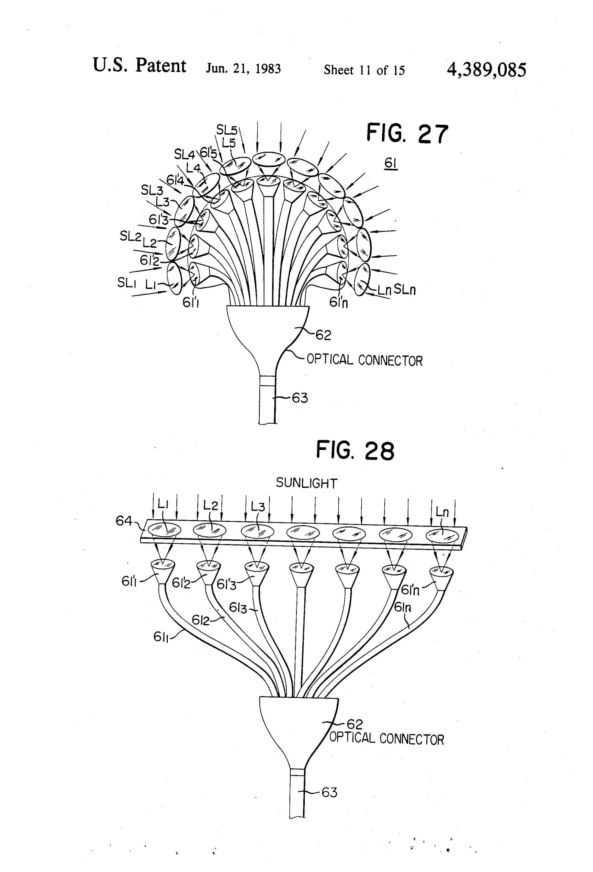
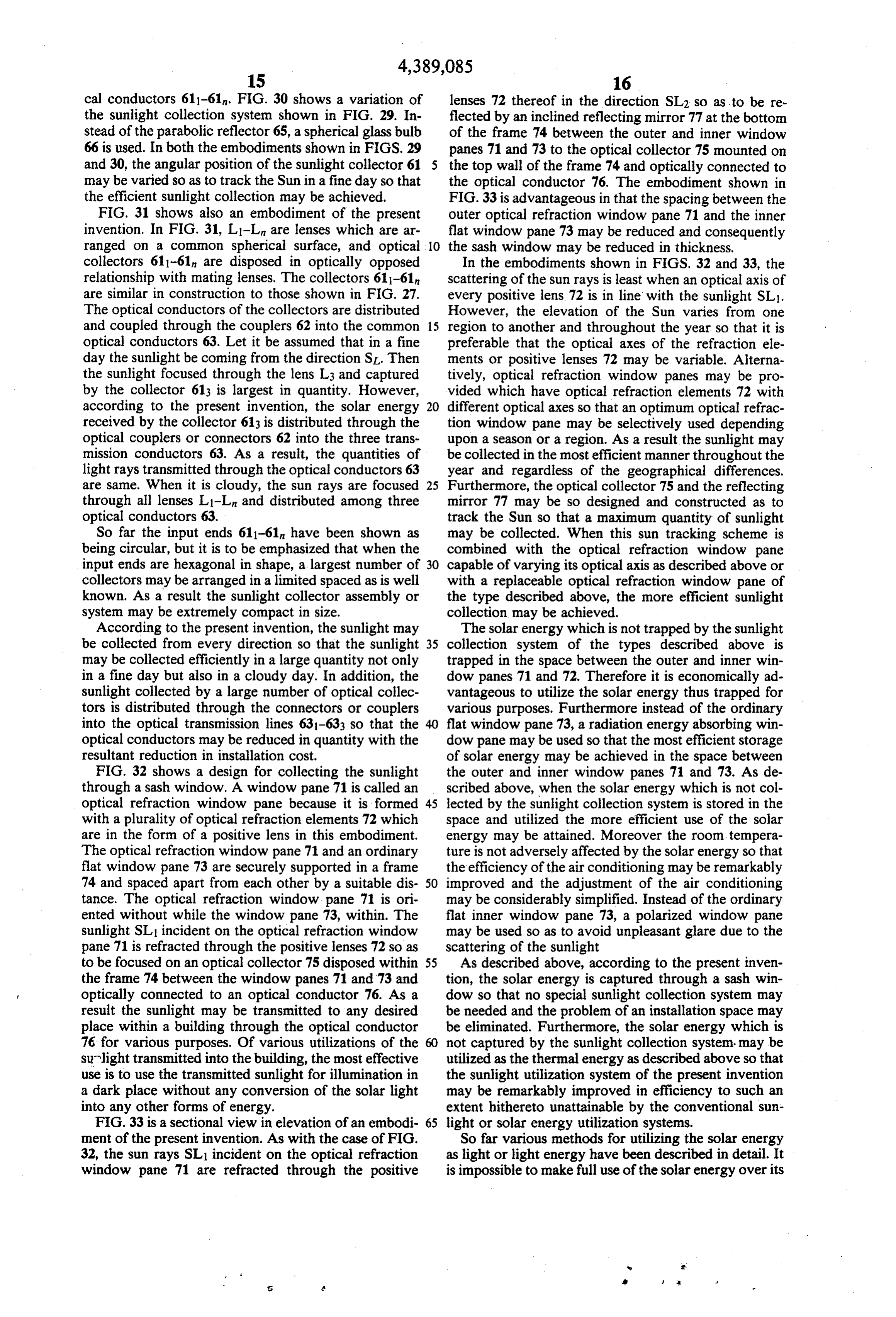
the Z-direction of the focal point position is caused by FIG. 26 is a view used for the explanation of the the time variations in the sunlight spectrum as observed underlying principle of a yet another embodiment of the on the ground. That is, as the time changes from the sunlight collection system used in the present invention. morning to the noon and the evening, the sunlight The sunlight collection system may collects efficiently a changes from the light containing a relatively large 35 considerable quantity of sunlight not only in a fine day quantity of red spectrum to the white light and then to but also a cloudy day. In FIG. 26, 61 is a sunlight collec the light containing again a relatively large quantity of tor; 611-61 and 63, optical conductors such as optical red spectrum. Furthermore the Z-direction deviation is fibers; 62, a connector for coupling light rays transmit also caused by the deformations of the casing exposed ted from the optical conductors 61 into a single optical to the shower of solar energy. 40 conductor 63. Light incident portions 611'-61' of the An embodiment shown in FIG. 25 is used for detect optical conductors 611-61n are oriented in various di ing the deviation in the Z-direction of the imaging point rections. For instance, the optical conductor 61 is so which is caused because of the reasons described above. oriented to capture the sunlight from the direction indi As shown in FIG. 23, a plurality of light sensors D1-D3 cated by the arrows SL through a lens L1; the optical are disposed along the periphery of the image 54 of the 45 conductor 612, the sunlight from the direction indicated Sun, and an additional light sensor D5 is located within by the arrows SL2 through a lens L2; and so on. The sun the image 54 itself. In response to the outputs from the rays transmitted through the optical conductors 61 are light sensors D1-D4, the deviations in the X- and Y coupled through the connectors 62 into the single opti directions of the focal point position are detected in the cal conductor 63 through which the sun rays are trans manner described above, and the deviations in the Z 50 mitted to the desired positions so as to be used for vari direction of the focal point position is detected by a ous purposes. Therefore when the light incident por differential amplifier A3 in response to the difference Zo tions or light input ends of the optical conductors between the output from the light sensor Ds within the 611-61 are arranged in the form of a semisphere as sun image on the one hand and the outputs from the shown in FIG. 27, the sun rays from all directions may light sensors D1-D4 around the sun image on the other 55 be coupled into the optical conductor 63. hand. The position of the optical conductor 52 in the FIG. 28 is a view used for the explanation of a still Z-direction is so controlled in response to the output further embodiment of the present invention. A plural from the amplifier A3 that the difference Zo in absolute ity of lenses L1-L are arranged in one row on a base 64 value may be maintained to a minimum. When the con so that they focus the images of the Sun on the incident trol in the Z-direction is effected normally, the quantity or input ends 611'-61' of the optical conductors of light coupled into the light conductor 52 varies so 611-61. The base may be mounted on a tracking device that the stable supply of light becomes impossible. so as to track the Sun, thereby more efficiently collect Therefore the control of the deviation in the Z-direc ing the sunlight.
tion of the focal point is effected at a predetermined FIG. 29 is a view used for the explanation of an em time interval or as shown in FIG. 23 a light sensor D6 is 65 bodiment of the present invention. As shown, the con provided which directly senses the sunlight energy so struction is much simplified because the sun rays are that when the sunlight energy detected by this light reflected by a parabolic reflector 65 so as to be incident sensor is less, that is, when it is overcast, the control in upon the light incident or input ends of individual opti
Page 24
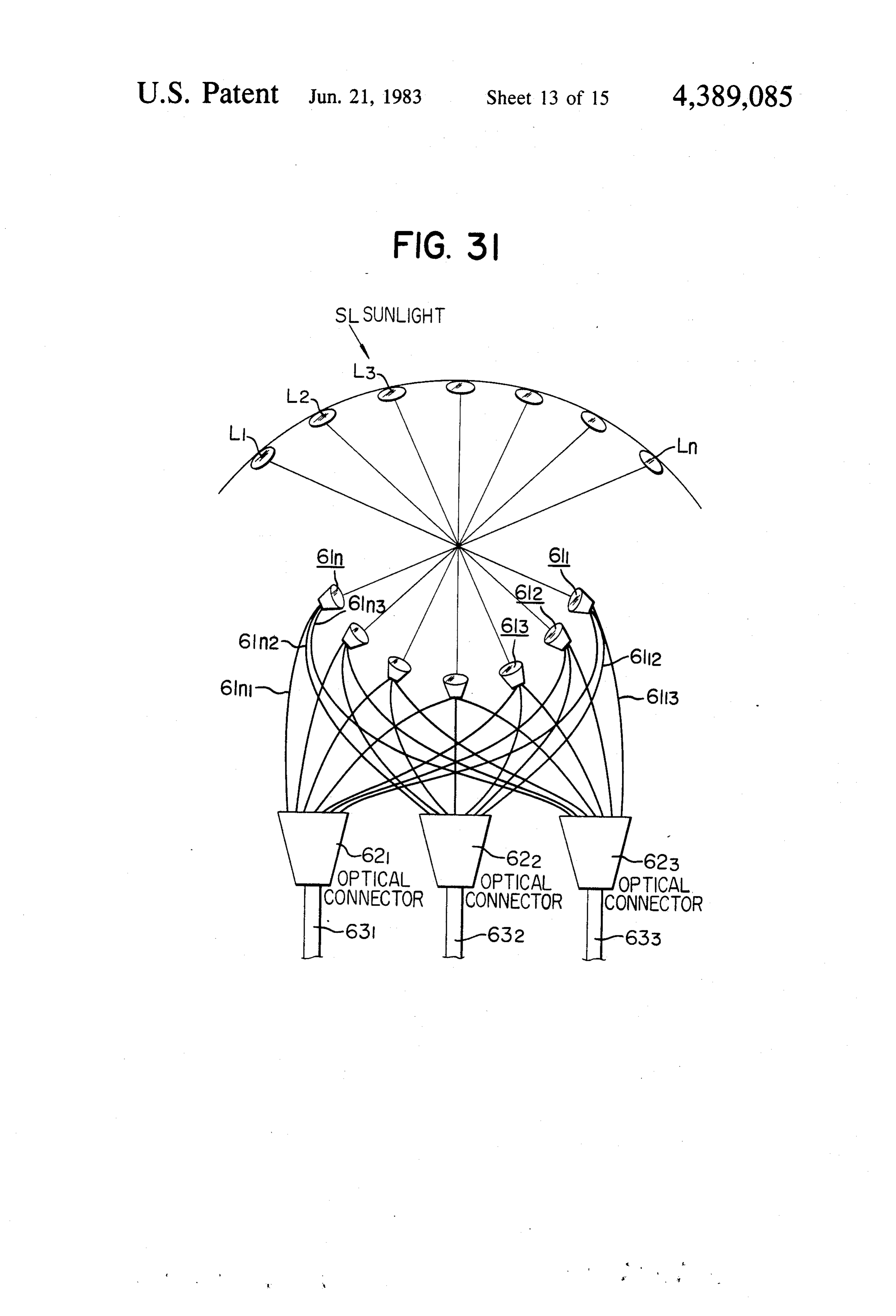
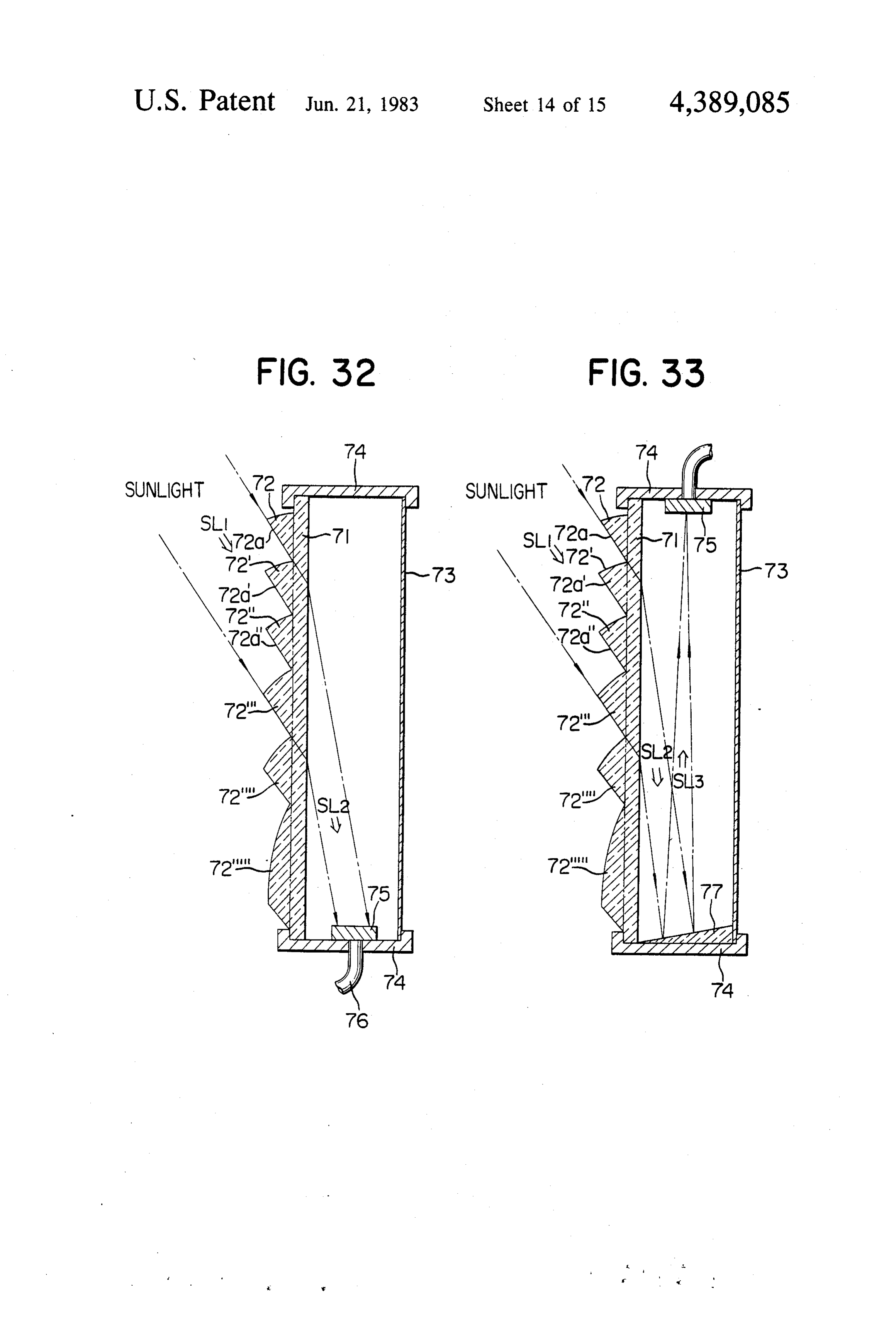
cal conductors 611-61. FIG. 30 shows a variation of lenses 72 thereof in the direction SL2 so as to be re the sunlight collection system shown in FIG. 29. In flected by an inclined reflecting mirror 77 at the bottom stead of the parabolic reflector 65, a spherical glass bulb of the frame 74 between the outer and inner window 66 is used. In both the embodiments shown in FIGS. 29 panes 71 and 73 to the optical collector 75 mounted on and 30, the angular position of the sunlight collector 61 the top wall of the frame 74 and optically connected to may be varied so as to track the Sun in a fine day so that the optical conductor 76. The embodiment shown in the efficient sunlight collection may be achieved. FIG.33 is advantageous in that the spacing between the FIG. 31 shows also an embodiment of the present Outer optical refraction window pane 71 and the inner invention. In FIG. 31, L-L are lenses which are ar flat window pane 73 may be reduced and consequently ranged on a common spherical surface, and optical O the sash window may be reduced in thickness. collectors 611-61n are disposed in optically opposed In the embodiments shown in FIGS. 32 and 33, the relationship with mating lenses. The collectors 611-61 scattering of the sun rays is least when an optical axis of are similar in construction to those shown in FIG. 27. every positive lens 72 is in line with the sunlight SL. The optical conductors of the collectors are distributed However, the elevation of the Sun varies from one and coupled through the couplers 62 into the common 15 region to another and throughout the year so that it is optical conductors 63. Let it be assumed that in a fine preferable that the optical axes of the refraction ele day the sunlight be coming from the direction SL. Then ments or positive lenses 72 may be variable. Alterna the sunlight focused through the lens L3 and captured tively, optical refraction window panes may be pro by the collector 613 is largest in quantity. However, vided which have optical refraction elements 72 with according to the present invention, the solar energy 20 different optical axes so that an optimum optical refrac received by the collector 613 is distributed through the tion window pane may be selectively used depending optical couplers or connectors 62 into the three trans upon a season or a region. As a result the sunlight may mission conductors 63. As a result, the quantities of be collected in the most efficient manner throughout the light rays transmitted through the optical conductors 63 year and regardless of the geographical differences. are same. When it is cloudy, the sun rays are focused 25 Furthermore, the optical collector 75 and the reflecting through all lenses L1-L and distributed among three mirror 77 may be so designed and constructed as to optical conductors 63. track the Sun so that a maximum quantity of sunlight So far the input ends 611-61 have been shown as may be collected. When this sun tracking scheme is being circular, but it is to be emphasized that when the combined with the optical refraction window pane input ends are hexagonal in shape, a largest number of 30 capable of varying its optical axis as described above or collectors may be arranged in a limited spaced as is well with a replaceable optical refraction window pane of known. As a result the sunlight collector assembly or the type described above, the more efficient sunlight system may be extremely compact in size. collection may be achieved.
According to the present invention, the sunlight may The solar energy which is not trapped by the sunlight be collected from every direction so that the sunlight 35 collection system of the types described above is may be collected efficiently in a large quantity not only trapped in the space between the outer and inner win in a fine day but also in a cloudy day. In addition, the dow panes 71 and 72. Therefore it is economically ad sunlight collected by a large number of optical collec vantageous to utilize the solar energy thus trapped for tors is distributed through the connectors or couplers various purposes. Furthermore instead of the ordinary into the optical transmission lines 631-633 so that the flat window pane 73, a radiation energy absorbing win optical conductors may be reduced in quantity with the dow pane may be used so that the most efficient storage resultant reduction in installation cost. of solar energy may be achieved in the space between FIG. 32 shows a design for collecting the sunlight the outer and inner window panes 71 and 73. As de through a sash window. A window pane 71 is called an scribed above, when the solar energy which is not col optical refraction window pane because it is formed 45 lected by the sunlight collection system is stored in the with a plurality of optical refraction elements 72 which space and utilized the more efficient use of the solar are in the form of a positive lens in this embodiment. energy may be attained. Moreover the room tempera The optical refraction window pane 71 and an ordinary ture is not adversely affected by the solar energy so that flat window pane 73 are securely supported in a frame the efficiency of the air conditioning may be remarkably 74 and spaced apart from each other by a suitable dis 50 improved and the adjustment of the air conditioning tance. The optical refraction window pane 71 is ori may be considerably simplified. Instead of the ordinary ented without while the window pane 73, within. The flat inner window pane 73, a polarized window pane sunlight SL incident on the optical refraction window may be used so as to avoid unpleasant glare due to the pane 71 is refracted through the positive lenses 72 so as scattering of the sunlight to be focused on an optical collector 75 disposed within 55 As described above, according to the present inven the frame 74 between the window panes 71 and 73 and tion, the solar energy is captured through a sash win optically connected to an optical conductor 76. As a dow so that no special sunlight collection system may result the sunlight may be transmitted to any desired be needed and the problem of an installation space may place within a building through the optical conductor be eliminated. Furthermore, the solar energy which is 76 for various purposes. Of various utilizations of the not captured by the sunlight collection system. may be surlight transmitted into the building, the most effective utilized as the thermal energy as described above so that use is to use the transmitted sunlight for illumination in the sunlight utilization system of the present invention a dark place without any conversion of the solar light may be remarkably improved in efficiency to such an into any other forms of energy. extent hithereto unattainable by the conventional sun FIG.33 is a sectional view in elevation of an embodi 65 light or solar energy utilization systems. ment of the present invention. As with the case of FIG. So far various methods for utilizing the solar energy 32, the sun rays. SL incident on the optical refraction as light or light energy have been described in detail. It window pane 71 are refracted through the positive is impossible to make full use of the solar energy over its
Page 25
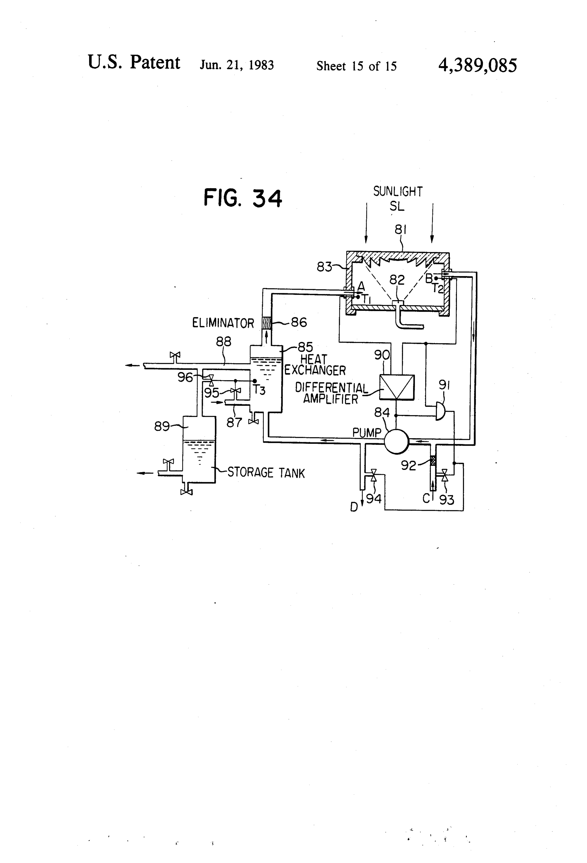
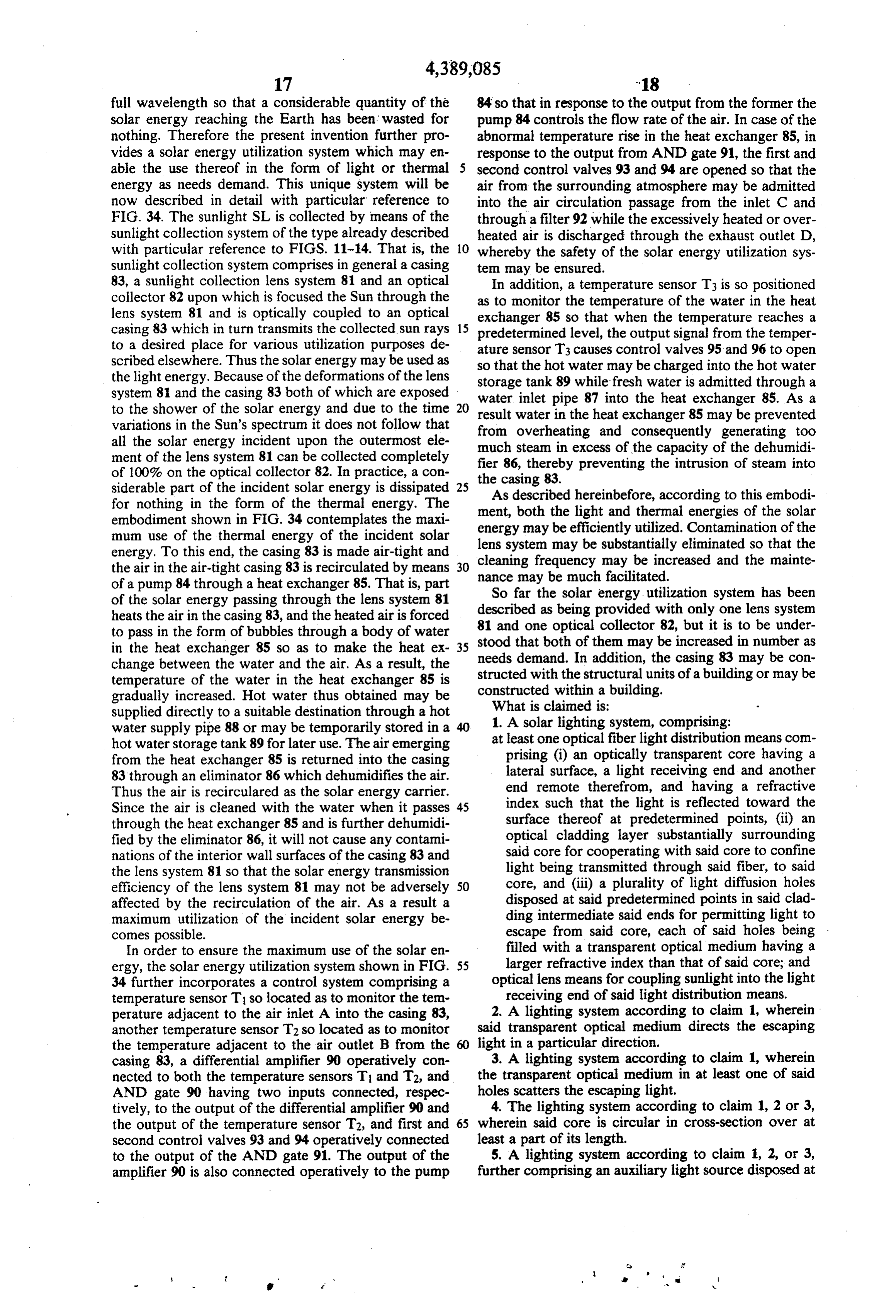
full wavelength so that a considerable quantity of the 84 so that in response to the output from the former the solar energy reaching the Earth has been wasted for pump 84 controls the flow rate of the air. In case of the nothing. Therefore the present invention further pro abnormal temperature rise in the heat exchanger 85, in vides a solar energy utilization system which may en response to the output from AND gate 91, the first and able the use thereof in the form of light or thermal second control valves 93 and 94 are opened so that the energy as needs demand. This unique system will be air from the surrounding atmosphere may be admitted now described in detail with particular reference to into the air circulation passage from the inlet C and FIG. 34. The sunlight SL is collected by means of the through a filter 92 while the excessively heated or over sunlight collection system of the type already described heated air is discharged through the exhaust outlet D, with particular reference to FIGS. 11-14. That is, the 10 whereby the safety of the solar energy utilization sys sunlight collection system comprises in general a casing ten may be ensured.
83, a sunlight collection lens system 81 and an optical In addition, a temperature sensor T3 is so positioned collector 82 upon which is focused the Sun through the as to monitor the temperature of the water in the heat lens system 81 and is optically coupled to an optical exchanger 85 so that when the temperature reaches a casing 83 which in turn transmits the collected sun rays 15 predetermined level, the output signal from the temper to a desired place for various utilization purposes de ature sensor T3 causes control valves 95 and 96 to open scribed elsewhere. Thus the solar energy may be used as so that the hot water may be charged into the hot water the light energy. Because of the deformations of the lens storage tank 89 while fresh water is admitted through a system 81 and the casing 83 both of which are exposed water inlet pipe 87 into the heat exchanger 85. As a to the shower of the solar energy and due to the time result water in the heat exchanger 85 may be prevented variations in the Sun's spectrum it does not follow that from overheating and consequently generating too all the solar energy incident upon the outermost ele much steam in excess of the capacity of the dehumidi ment of the lens system 81 can be collected completely of 100% on the optical collector 82. In practice, a con fier the 86, thereby preventing the intrusion of steam into casing 83.
siderable part of the incident solar energy is dissipated 25 As described hereinbefore, according to this embodi for nothing in the form of the thermal energy. The embodiment shown in FIG. 34 contemplates the maxi ment, both the light and thermal energies of the solar mun use of the thermal energy of the incident solar energy may be efficiently utilized. Contamination of the energy. To this end, the casing 83 is made air-tight and lens system may be substantially eliminated so that the the air in the air-tight casing 83 is recirculated by means 30 cleaning frequency may be increased and the mainte of a pump 84 through a heat exchanger 85. That is, part nance may be much facilitated. So far the solar energy utilization system has been of the solar energy passing through the lens system 81 described heats the air in the casing 83, and the heated air is forced 81 and oneasoptical being provided with only one lens system collector 82, but it is to be under to pass in the form of bubbles through a body of water stood that both of them may be increased in number as in the heat exchanger 85 so as to make the heat ex 35 needs demand. In addition, the casing 83 may be con change between the water and the air. As a result, the structed with the structural units temperature of the water in the heat exchanger 85 is constructed within a building. of a building or may be gradually increased. Hot water thus obtained may be What is claimed is:
supplied directly to a suitable destination through a hot 1. A solar lighting system, comprising: water supply pipe 88 or may be temporarily stored in a hot water storage tank 89 for later use. The air emerging at least one optical fiber light distribution means com from the heat exchanger 85 is returned into the casing prising (i) an optically transparent core having a 83 through an eliminator 86 which dehumidifies the air. lateral surface, a light receiving end and another Thus the air is recirculared as the solar energy carrier. end remote therefrom, and having a refractive Since the air is cleaned with the water when it passes 45 index such that the light is reflected toward the through the heat exchanger 85 and is further dehumidi surface thereof at predetermined points, (ii) an fied by the eliminator 86, it will not cause any contami optical cladding layer substantially surrounding nations of the interior wall surfaces of the casing 83 and said core for cooperating with said core to confine the lens system 81 so that the solar energy transmission light being transmitted through said fiber, to said efficiency of the lens system 81 may not be adversely 50 core, and (iii) a plurality of light diffusion holes affected by the recirculation of the air. As a result a disposed at said predetermined points in said clad maximum utilization of the incident solar energy be ding intermediate said ends for permitting light to comes possible. escape from said core, each of said holes being In order to ensure the maximum use of the solar en filled with a transparent optical medium having a ergy, the solar energy utilization system shown in FIG. 55 larger refractive index than that of said core; and 34 further incorporates a control system comprising a optical lens means for coupling sunlight into the light temperature sensor Tso located as to monitor the tem receiving end of said light distribution means. perature adjacent to the air inlet A into the casing 83, 2. A lighting system according to claim 1, wherein another temperature sensor T2 so located as to monitor said transparent optical medium directs the escaping the temperature adjacent to the air outlet B from the light in a particular direction.
casing 83, a differential amplifier 90 operatively con 3. A lighting system according to claim 1, wherein nected to both the temperature sensors T and T2, and the transparent optical medium in at least one of said AND gate 90 having two inputs connected, respec holes scatters the escaping light.
tively, to the output of the differential amplifier 90 and 4. The lighting system according to claim 1, 2 or 3, the output of the temperature sensor T2, and first and 65 wherein said core is circular in cross-section over at second control valves 93 and 94 operatively connected least a part of its length.
to the output of the AND gate 91. The output of the 5. A lighting system according to claim 1, 2, or 3, amplifier 90 is also connected operatively to the pump further comprising an auxiliary light source disposed at
Page 26
the light receiving end of said core for use when there propagation conditions and controlling said light source is no sunlight. responsive thereto.
6. The lighting system according to claim 5, further 9. A lighting system according to claim 1, 2, or 3, comprising light reflective means disposed at said other wherein said core comprises an optically transparent end of said core for reflecting light back toward said 5 thin film.
light receiving end thereof. 10. The solar lighting system of claim 1 comprising a 7. A lighting system according to claim 5, wherein plurality of optical lens means, each of which couples said light distribution means comprises a number of the sunlight to one of a plurality of optical collectors, optical fibers each having said core and cladding layer, each of said optical collectors being optically connected each fiber having an end terminating at one of said 10 to each of a plurality of optical connectors associated predetermined points for radiating light therefrom. with each of a plurality of optical fiber light distribution 8. A lighting system according to claim 5, further means whereby each light distribution means receives comprising a light exit at said other end of said core and sunlight from all of said lenses and collectors. a light sensor disposed thereat for monitoring light
Provenance
- Collection
- Cited prior art
- Original PDF
- patentimages.storage.googleapis.com →
- Filed
- 1981-12-16
- Pages
- 26
- Method
- pdftotext (the PDF's own text layer) + pdftoppm 300dpi page scans
- Source
- Google Patents bibliographic record
- Granted
- 1983-06-21
- Inventors
- Kei Mori
- Transcribed from
- patentimages.storage.googleapis.com →