patent · US4297000
Solar lighting system
27 October 1981
Page 1 — bibliographic record
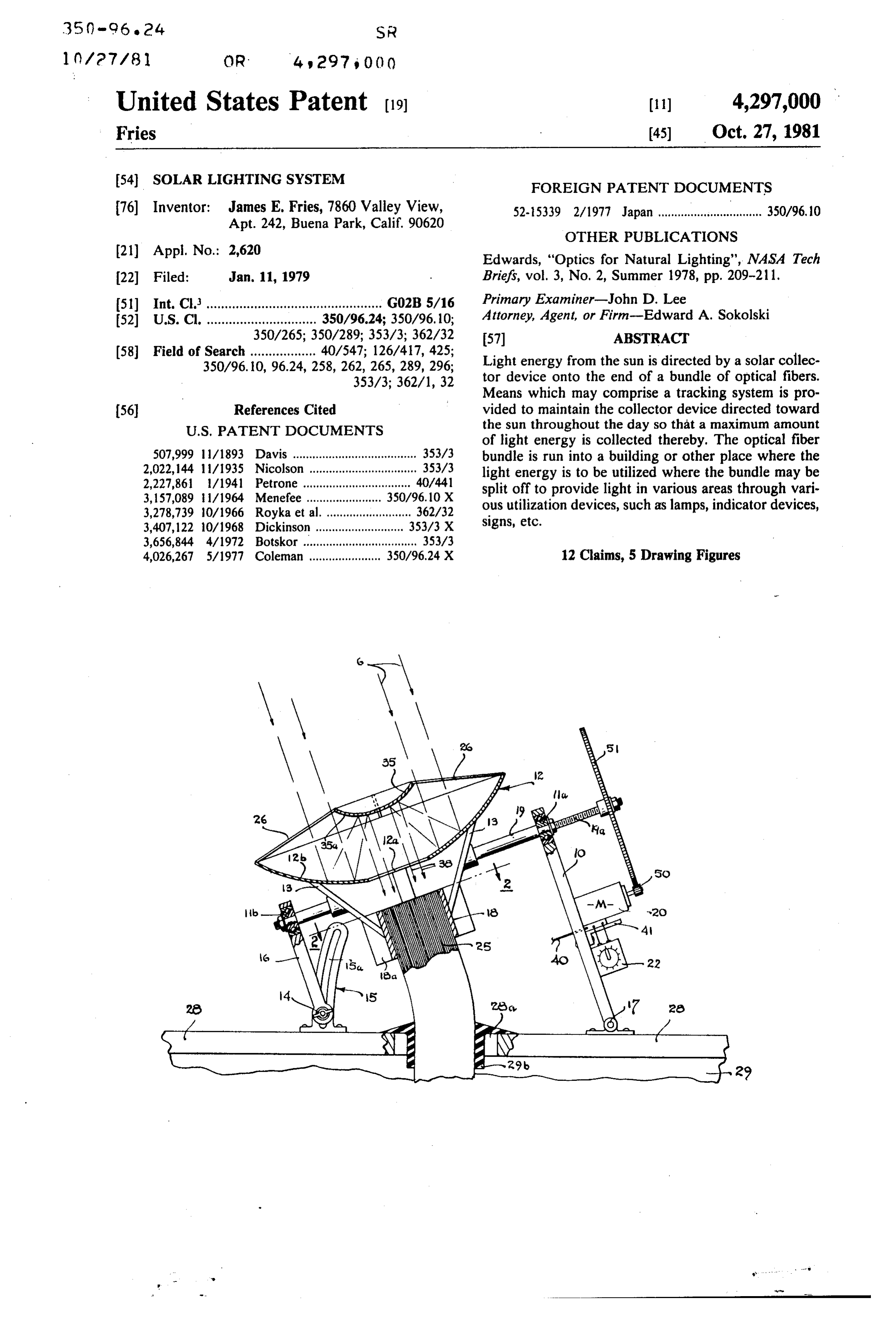
United States Patent (19) (11) 4,297,000 Fries (45 Oct. 27, 1981 54). SOLAR LIGHTING SYSTEM FOREIGN PATENT DOCUMENTS 76) Inventor: James E. Fries, 7860 Valley View, 52-5339 2/1977 Japan ................................ 350/96, 10 Apt. 242, Buena Park, Calif. 90620
OTHER PUBLICATIONS
(21) Appl. No.: 2,620 Edwards, "Optics for Natural Lighting", NASA Tech 22 Filed: Jan. 11, 1979 Briefs, vol. 3, No. 2, Summer 1978, pp. 209-211. 51) Int. Cl................................................. GO2B 5/16 Primary Examiner-John D. Lee 52 U.S. C. .............................. 350/96.24; 350/96. 10; Attorney, Agent, or Firm-Edward A. Sokolski 350/265; 350/289; 353/3; 362/32 57 ABSTRACT 58 Field of Search .................. 40/547; 126/417,425; Light energy from the sun is directed by a solar collec
353/3; 362/1, 32 tor device onto the end of a bundle of optical fibers.
Means which may comprise a tracking system is pro (56) References Cited vided to maintain the collector device directed toward
of light energy is collected thereby. The optical fiber 507,999 11/1893 Davis ...................................... 353/3 bundle is run into a building or other place where the 2,022,44 1 1/1935 Nicolson ................................. 353/3 light energy is to be utilized where the bundle may be 2,227,861 /1941 Petrone ................................. 40/441 split off to provide light in various areas through vari 3,157,089 1/1964 Menefee ....... ... 350/96.10 X 3,278,739 10/1966 Royka et al........................... 362/32 ous utilization devices, such as lamps, indicator devices, 3,407,122 10/1968 Dickinson. ... 353/3 X signs, etc.
3,656,844 4/1972 Botskor ................................., 353/3 4,026,267 5/1977 Coleman ...................... 350/96.24 X 12 Claims, 5 Drawing Figures
Page 2
Drawing sheet — no readable text.
Page 3
Drawing sheet — no readable text.
Page 4
Briefly described, the system of the invention is as
SOLAR LIGHTING SYSTEM follows: A collector device, which in a preferred em bodiment is in the form of a parabolic mirror operating
This invention relates to a lighting system, and more in conjunction with a convex mirror (employed to make particularly to such a system which utilizes solar energy 5 the light rays more parallel so they will enter the optical as its light source. fibers at an optimum angle) and which in other embodi The use of solar energy has received widespread ments comprises a focusing lens or a parabolic mirror attention in recent years as an approach to the conserva by itself, is used to focus light from the sun onto the tion of energy. While many solar energy systems have ends of a bundle of optical fibers which are supported in been developed for heating, distillation, and the genera 10 line with the light beam provided by the collector de tion of electricity, little or no attention has been given to vice. A tracking system is employed to slew or position its potential for providing light to enclosed quarters the collector so that it remains directed on the sun where a substantial amount of electrical energy is used throughout the day. For illustrative purposes, an equa during the daylight hours in offices, homes, theaters, torial mounting of the mirrors is shown. An azimuthal restaurants, stores, factories, tunnels, mines, etc. 5 or other mounting could also be employed. The optical Optical fiber lines and cables of one type or another fiber bundle is fed from the outside into the areas to be have been available for many years, particularly for illuminated where the bundle may be separated out into applications such as transmission of light to indicator smaller bundles if desired and even single fibers sepa lights, for carrying modulated light waves in communi rated for providing light energy to various light utiliza cation systems (these light waves often being generated 20 tion devices, such as lamps, lighted signs, indicators, by lasers), and in optic data links. In U.S. Pat. No. bulbs or tubes with light dispersing properties, etc., as 3,278,739 to Royka et al. and U.S. Pat. No. 2,227,861 to may be desired.
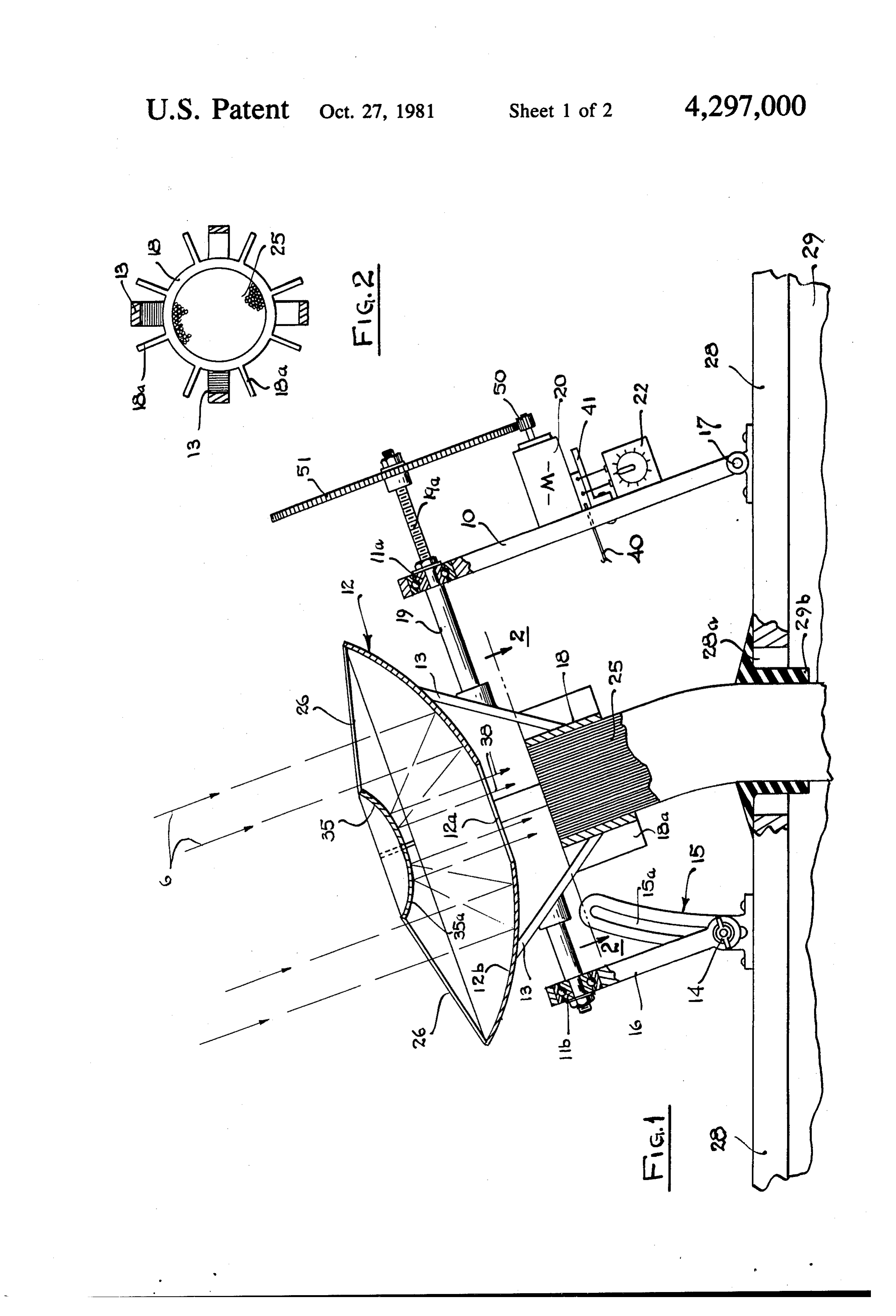
Petrone, the use of glass rods and fiber optics for distrib Referring now to FIGS. 1 and 2, a preferred embodi uting light from a single light source to a plurality of ment of the invention is illustrated. Collector device 12, light emitters is shown. In these systems, however, the 25 which is in the form of a dish reflective on the upper light energy is taken from an artificial light source and surface is supported by means of braces 13 which are there is no suggestion of means for employing solar fixedly attached to shaft 19 and ring-shaped holder 18. energy as the source of light energy. The collector has a parabolic reflector 12b on one side The present invention provides a system for collect thereof. Holder 18 is used to hold the optical fiber bun ing light from the sun and transmitting this light by fiber 30 dle 25 in place. The shaft 19 is rotatably supported by optics to light utilization devices, thereby decreasing means of roller bearings 11a and 11b on support bars 10 the need for artificial light energy sources during broad and 16, respectively. Bar 10 is pivotally supported on daylight hours, and in this manner conserving energy. base member 28 by means of hinge member 17. Base The system of the present invention also can be used as member 28 may be mounted against the roof 29 of the an emergency lighting system to augment or replace the 35 building. Bar 16 is attached by means of wing nut and regular lighting system in the event of a power failure washer to a slotted bracket 15, this bracket being sup or power reduction. The system is also useful to provide ported on base member 28, Bar 16 may thus be slid lighting in mines, reducing power needs for electric along the slot 15a of the bracket to adjust the angle of lighting or gas lighting, the former of which is expen mirror 12 on a north-south axis. The wing nut 14 is used sive in wilderness areas and the latter of which can be 40 to lock the bar in the desired position. This adjustment somewhat hazardous. By using a photocell to regulate is made on a daily or weekly basis to position the para the electric lights, a constant source of illumination bolic mirror along an optimum axis for collecting the could be provided on cloudy or overcast days when sun's rays.
solar energy is inadequate or intermittent in intensity. Supported above the parabolic mirror 12 by means of It is therefore an object of this invention to provide 45 struts 26 is a convex mirror 35 which has a convex means for conserving energy. reflective surface 35a, Parabolic mirror 12 has a circular It is further an object of this invention to provide an aperture 12a formed in the center thereof, this aperture emergency lighting system. having a diameter at least as large as that of the fiber It is an additional object of this invention to provide bundle 25. The holder 18 for the fiber optical bundle has a lighting system which utilizes the sun's rays for its 50 a plurality of cooling fins 18a thereon to dissipate heat lighting source. energy. In larger mirror assemblies, the ring shaped Other objects of this invention will become apparent holder 18 may be hollowed and cooling water circu as the description proceeds in connection with the ac lated through it to effect an additional cooling of the companying drawings of which: optical fiber bundle.
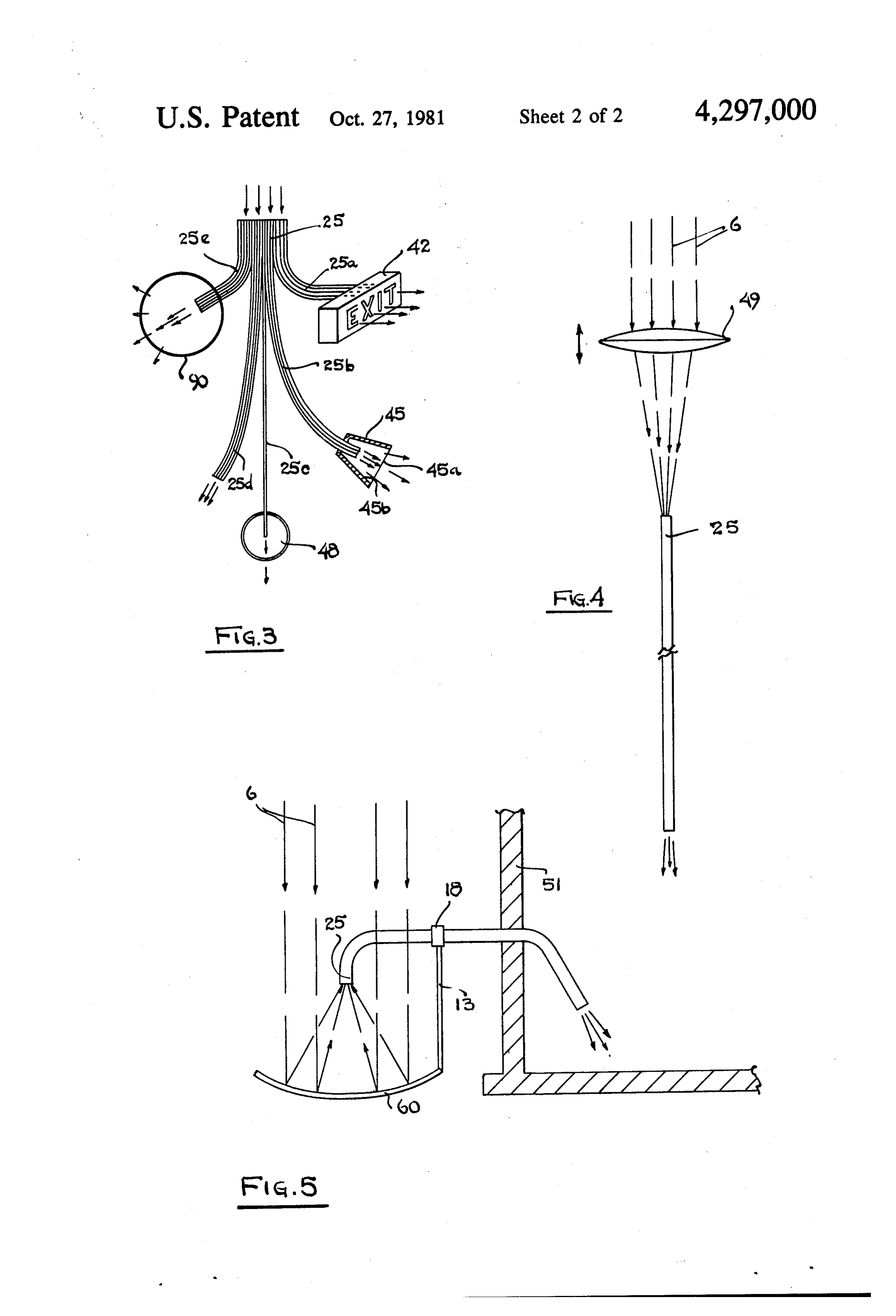
FIG. 1 is an elevational view of a preferred embodi 55 Fixedly supported on a shelf 41 which in turn is sup ment of the invention; ported on bar 10 is an electric motor 20. The operation FIG. 2 is a cross sectional view taken along the plane of this motor is controlled by timer 22 which is also indicated by 2-2 in FIG. 1 and illustrating the fiber supported on bar member 10. The drive shaft of motor bundle employed in a preferred embodiment and its 20 has a pinion gear 50 attached thereto, this pinion gear associated cooling fins; 60 rotatably driving ring gear 51 which is fixedly attached FIG. 3 is a schematic illustration illustrating some of to an undercut threaded portion 19a of shaft 19. Timer the various light utilization devices which may be used 22 is set and adjusted such that the shaft 19, parabolic with the optical fiber terminals; mirror 12 and convex mirror 35 which are supported FIG. 4 is an alternative embodiment of a collector thereon are rotatably driven to follow the sun through which may be utilized in implementing the invention; out the day on an east-west axis. The mirrors move on and this axis 15 degrees of rotation per hour and stop at a FIG. 5 is a further embodiment of a collector which preset time at sundown, the mirrors being set at a prede may be utilized in implementing the invention. termined position fixed at a time in the morning.
Page 5
Fiber optical bundle 25 and power line 40 are fed means for slewing the focusing means and said one through aperture 28a in base 28 and a corresponding end of said fiber optical means together so as to aperture and sealing gasket 29b in the top of roof 29 into follow the sun with the rays of the sun being main the areas where illumination is required as shown in tained in focus on said fiber optical line means, FIG. 3. As shown in FIG. 3, bundle 25 may be split off 5 light utilization means, and into a first sub-bundle 25a which is utilized to illuminate means for coupling the other end of said fiber optical a transparent sign 42, for example, and even into a sec line means to said light utilization means so as to ond sub-bundle 25b which is fed into a clear glass effect the illumination of said light utilization "bulb" device 45 which has a glass window 45a and a . eaS.
reflective conical side portion 45b, this device function 10 2. The system of claim 1 wherein said fiber optical ing as a lamp. Single fiber 25c is fed to indicator bulb 48. line means comprises a bundle of optical fibers. Additional sub-bundles 25d may be used for other light 3. The system of claim 2 wherein said light utilization ing purposes and sub-bundle 25e may be used to illumi means comprises a plurality of light utilization devices, nate bulb 90 with a light scattering coating or etching. said bundle of optical fibers being split into a plurality of Thus as can be seen, the light rays 6 from the sun are 15 bundles, each of said bundles being coupled to a sepa focused by parabolic reflector 12 onto convex mirror rate one of said devices.
surface 35 which reflects the focused light rays 38 onto 4. The system of claim 1 wherein the means for focus optical bundle 25. The light is transmitted by the fibers ing the sun's rays comprises a collector device having of optical fiber bundle 25 into the areas to be lighted an aperture formed in the center thereof, a parabolic where the bundle may be divided into several bundles 20 reflector on one side thereof, a convex mirror, means and individual fibers to illuminate various lighting de for supporting said one end of said fiber optical line vices. Suitable optical fibers and cables which may be means opposite said aperture on the other side of said formed into bundles are generally commercially avail collector device, and means for supporting said convex able. In an operative embodiment of the invention, an mirror opposite the parabolic reflector of said collector optical fiber cable whose individual fibers have diame 25 device at a position which is substantially at the focus of ters of 68 microns is employed. the parabolic reflector to direct the light rays focused Referring now to FIG.4, a second embodiment of the by the reflector onto said one end of said fiber optical invention is schematically illustrated. This second em line means.
bodiment differs from the first in that rather than em 5. The system of claim 4 and further including means ploying a mirror system for collecting the sunlight, the 30 for slewing said collector device and said convex mirror sunlight is focused on the optical fibers by means of a so as to follow the sun.
lens 49. Thus, the light rays 6 are concentrated on the 6. The system of claim 4 wherein the means for sup optical fibers 25 by the lens. Lens 49 may be mounted porting said one end of the fiber optical line means along with the fiber optical bundle and driven so as to comprises a ring-shaped holder which holds said one track the sun in the same manner as for the previous 35 end of said line means and means for attaching said embodiment. The lens 49 may also employ a double holder to said collector device.
concave lens to make the rays more parallel for a more 7. The system of claim 6 and further including cool efficient entry into the optical fibers. ing fins extending outwardly from said holder. Referring now to FIG. 5, a further embodiment of 8. The system of claim 1 wherein the means for focus the invention is shown. In this embodiment, a single 40 ing the rays of the sun comprises an optical lens. parabolic mirror 60 is used with the sun's rays 6 being 9. The system of claim 1 wherein the means for focus focused by this mirror onto the ends of fiber optical ing the rays of the sun comprises a parabolic reflector. bundle 25. This mirror may also employ a double con 10. A lighting system employing solar light energy cave lens to cause the light rays to be more parallel. comprising:
Here, again, the mirror may be supported and driven to 45 a collector device in the form of a dish having an track the sun in the same manner as for the first embodi aperture in the center thereof, a parabolic reflec ment. The optical bundle or cable 25 is fed through the tive surface on one side thereof, wall 51 of a building. a fiber optical cable formed from a plurality of optical As has been noted, the system of the invention has fiber lines joined together into a bundle, widespread application, not only as a substitute or aug 50 ring holder means for holding one end of said fiber mentative lighting system in a great many situations, but optical bundle together, also as a back-up system for emergency use in the event support means for supporting said collector device that the power should fail. In such situation, the track for rotatable movement about a predetermined ing system may not have electric drive but could be set axis, manually or have a battery to power the electric drive 55 means for supporting said ring holder means on said under emergency situations. collector device for movement therewith with said While the invention has been described and illus one end of said cable on the opposite side of said trated in detail, it is to be clearly understood that this is collector device and facing directly opposite said intended by way of illustration and example only and is aperture, the one end of the fiber optical bundle not to be taken by way of limitation, the spirit and scope 60 held by the ring holder means moving along with of this invention being limited only by the terms of the the collector device to maintain said one end of following claims. said cable facing directly opposite said aperture, I claim: a convex mirror, 1. A lighting system employing solar light energy means for supporting said convex mirror on said comprising: 65 collector device on said one side thereof approxi fiber optical line means, mately at the parabolic focal distance from said means for focusing the rays of the sun onto one end of parabolic surface, said fiber optical line means, light utilization means,
Page 6
means for coupling the other end of said cable to said said fiber optical cable and transmitted to said light utilization means.
light utilization means, and 11. The system of claim 10 and further including means for slewing said collector device about said cooling fins extending outwardly from said ring holder predetermined axis so as to maintain said collector 5 2S.
device directed at the sun, 12. The system of claim 10 wherein said slewing means whereby the sun's rays are focused on said convex actuation comprises a motor, a timer for controlling the of said motor and a gear train for coupling mirror by said parabolic surface, said convex mir said motor to said collector device.
ror directing the focused rays onto said one end of 10
Provenance
- Collection
- Cited prior art
- Original PDF
- patentimages.storage.googleapis.com →
- Filed
- 1979-01-11
- Pages
- 6
- Method
- pdftotext (the PDF's own text layer) + pdftoppm 300dpi page scans
- Source
- Google Patents bibliographic record
- Granted
- 1981-10-27
- Inventors
- James E. Fries
- Transcribed from
- patentimages.storage.googleapis.com →